EP0288043A2 - Simulationsverfahren für Programme - Google Patents
Simulationsverfahren für Programme Download PDFInfo
- Publication number
- EP0288043A2 EP0288043A2 EP88106337A EP88106337A EP0288043A2 EP 0288043 A2 EP0288043 A2 EP 0288043A2 EP 88106337 A EP88106337 A EP 88106337A EP 88106337 A EP88106337 A EP 88106337A EP 0288043 A2 EP0288043 A2 EP 0288043A2
- Authority
- EP
- European Patent Office
- Prior art keywords
- program
- programs
- processors
- processor
- level
- Prior art date
- Legal status (The legal status is an assumption and is not a legal conclusion. Google has not performed a legal analysis and makes no representation as to the accuracy of the status listed.)
- Granted
Links
Images


Classifications
-
- G—PHYSICS
- G06—COMPUTING OR CALCULATING; COUNTING
- G06F—ELECTRIC DIGITAL DATA PROCESSING
- G06F11/00—Error detection; Error correction; Monitoring
- G06F11/30—Monitoring
- G06F11/34—Recording or statistical evaluation of computer activity, e.g. of down time, of input/output operation ; Recording or statistical evaluation of user activity, e.g. usability assessment
-
- G—PHYSICS
- G06—COMPUTING OR CALCULATING; COUNTING
- G06F—ELECTRIC DIGITAL DATA PROCESSING
- G06F11/00—Error detection; Error correction; Monitoring
- G06F11/36—Prevention of errors by analysis, debugging or testing of software
- G06F11/3698—Environments for analysis, debugging or testing of software
Definitions
- the present invention relates, in a distributed processing system for executing a series of processes with a plurality of programs, to a simulation method for evaluating the performances of the programs.
- An object of the present invention is to provide, in the distributed processing system, a simulation method for programs which facilitates the development of a system and which enhances the reliability of software.
- the present invention consists in giving each program the input/output data thereof, a processor for storing the program, and information on the processing time of the program beforehand, and comprising:
- system flow the starting flow of the series of programs
- step (2) is applied to the system flow generated by the step (1), whereby the processing time of the whole system flow can be calculated.
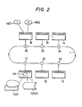
- FIG. 2 is a whole architecture diagram of a system to which the method of the present invention is applied.
- a common transmission path for connecting individual processors will be illustrated as a single-loop transmission system by way of example, any of general transmission media may well be employed.
- numerals 11 - 16 indicate processors whose internal memories store application programs and which execute the programs, and numeral 1 indicates a unidirectional loop transmission path which transmits data in the direction of arrows.
- Numerals 21 - 26 denote network control processors (hereinbelow, termed "NCPs") which control the data transmission on the transmission path.
- NCPs network control processors
- the respective NCPs 21 - 26 and the corresponding processors 11 - 16 are connected bidirectionally. Processed results (data) in the processors 11 - 16 are broadcast onto the transmission path via the NCPs 21 - 26.
- Each of NCPs 21 - 26 decides if data flowing on the transmission path is necessary for the processor connected to its own, and it sends the data to its own processor only when the data has been decided necessary.
- Each of the processors 11 - 16 starts the application program stored therein at the point of time at which all data items necessary for the execution of the program have been completely gathered. The started program executes its own process by the use of the data items, and outputs the result of the process.
- the processor 11 is assumed to be a development system.
- a program 101 for performing the simulation method of the present invention is set in the processor 11, and a CRT terminal 1001 for a man-machine interface and a file 10001 for storing tables required for the execution of the method are connected to this processor.
- the processor 16 is an I/O managing processor, to which an external input unit 1601 and an external output unit 1602 are connected. This processor 16 fetches data from an external process through the external input unit 1601 and delivers the data onto the transmission path, while it fetches data from the transmission path and delivers the data to an external process through the external output unit 1602.
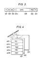
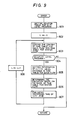
- Fig. 3 Shown in Fig. 3 is the format of data which flows on the transmission path.
- Symbol CC 302 denotes a content code, which is a code corresponding to the content of the data. On the basis of this contend code, each NCP judges whether or not the received data is necessary for the processor connected to its own.
- Symbol SA 303 denotes an NCP address having sent the message, and symbol C 304 a consecutive number required for transmission.
- DATA 305 indicates the data of the processed result of each application program, and FCS 306 indicates error sensing data.
- F 301 and F 307 denote flags which indicate the start and end of the message, respectively.
- the present invention is directed toward the distributed processing system as explained above, and is intended to simulate the operations of the application programs in the case where these programs are set in the respective processors. Now, the simulation method of the present invention will be described with reference to Fig. 4 - Figs. 10(a) and 10(b).
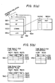
- Fig. 4 and Figs. 5(a) and 5(b) show the formats of the tables which are set in the file indicated at numeral 10001 in Fig. 2.
- Fig. 4 shows the table which stores information on the respective programs, and which shall hereinafter be called the "program constitution table.”
- This table is made up of the tables (401, 402, (2003)) of the respective programs.
- the individual tables are assinged serial numbers, which shall be called "program Nos.”
- the format of the table 401 will be elucidated.
- the tables 402, ...... have the same format.
- Symbol ICC 4011 denotes an area in which the content code of data to serve as the input of the corresponding program is stored
- symbol OCC 4012 denotes an area in which the content code of the output data of the program is stored
- TIME 4013 indicates an area for storing the processing time of the program
- PNO 4014 an area for storing the processor No. of the processor in which the program is stored
- PINF 4015 an area for storing the attribute of the program (for example, the program identifier).
- the program constitution table shall be previously set before the execution of the method of the present invention.
- this table can be set by keying-in the necessary information items from the CRT terminal (1001 in Fig. 2).
- Figs. 5(a) and 5(b) show the tables which are generated on the basis of the program constitution table shown in Fig. 4 by the method of the present invention.
- Fig. 5(a) shows the table indicative of the relations among the programs (hereinafter, called the "program relation table").
- the program relation table is made up of the tables 551 - 55m of the respective programs, and these tables are identified by respectively assigned serial Nos. (program relation table Nos.).
- the tables 552 - 55m have the same format.
- the table 551 is configured of a program pointer PP 5511, a table status ST 5512, a downstream information DOWNI 5513, and a level area LEV 5514.
- the program pointer PP 5511 is an area for storing a pointer which indicates the position of the program corresponding to this table, within the program constitution table (Fig. 4), and it has the program No. set therein.
- the table status ST 5512 is an area for setting therein information which indicates whether this table is in a normal status or in a relay status.
- the downstream information DOWNI 5513 there is stored the information of the program which lies downstream on the data flow of the program corresponding to this table.
- the area DOWNI is composed of content codes OCC 551310 which this program delivers as outputs, and pointers PRP 551311 which indicate the positions of the programs for receiving data items having the content codes as inputs, within the program constitution table.
- the pointers PRP 551311 are the program Nos. of the program constitution table shown in Fig. 4.
- Fig. 5(b) shows the tables which are generated on the basis of the program relation table shown in Fig. 5(a) during the execution of the simulation of the present invention, and which serve to store elaspsed times at the several stages of the simulation.
- the table 560 is a table (a time table for flows) which stores the elapsed times of a series of respective programs (hereinafter, called "system flows") that are successively started, and which is made up of rows 5601, 5602, « that correspond to the respective flows.
- the first row 5601 is composed of an area PMD 56011 for storing information which indicates an adjacent program lying upstream of a program being presently handled, an area CMD 56012 for storing information which indicates the program being presently handled, and an area TM 56013 for storing the elapsed time.
- the second row 5602, et seq. have the same composition as that of the first row 5601.
- the table 1560 is a table (a time table for previous-level flows) which serves to keep the contents of the table 560 and which has the same format as that of the table 560.
- the table 570 is a table (a time table for processors) which stores the elapsed times of the respective processors, and which is made up of rows 5701, 5702, ....
- the first row 5701 is composed of an area PN 57011 for storing processor No., and an area TM 57012 for storing the elapsed time.
- the second row 5702, et seq. have the same composition as that of the first row 5701.
- Fig. 1 shows the processing flow of the program 101 within the processor 11 shown in Fig. 2.
- the program 101 carries out the simulation in accordance with inputs from the CRT terminal 1001.
- information which triggers a system flow (programs) for starting the simulation (the identifier of a program to be first started, or the content code of data to be input to the program) is fetched from the CRT terminal 1001 (step 1011).
- the system flow which is started by the trigger obtained at the step 1011 is generated on the basis of the contents of the program constitution table shown in Fig. 4 (step 1012).
- step 1013 the processing time of the whole system flow is calculated (step 1013) on the basis of the system flow obtained at the step 1012, and the processing time information items (TIME 4013 in Fig. 4) and processor Nos. (PNO 4014 in Fig. 4) of the individual programs contained in the program constitution table.
- the calculated result is output to the CRT terminal 1001 (step 1014).
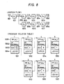
- Figs. 6(a) and 6(b) exemplify the application programs which are set in the system shown in Fig. 2.
- Fig. 6(a) schematically depicts the relation among the programs (the system flow).
- the processor 16 fetches data from the external input unit 1601, and supplies the transmission path with data 651 having a content code CC1. This data becomes the input data of a program A1 (601).
- the program A1 executes a process in accordance with the content of the input data 651, and outputs data 652 having a content code CC2 as the result.
- the data 652 becomes the input data of programs A2 (602) and A5 (605).
- the programs A2 and A5 execute processes according to the input data, and they output data items 653 and 656 having content codes CC3 and CC6, respectively.
- a program A3 (603) is started by the data 653 and outputs data 654 having a content code CC4, whereupon a program A4 (604) is started by data 654 and outputs data 655 having a content code CC5.
- programs A6 (606) and A7 (607) are successively started by the data 656, and the program A7 outputs data 658 having a content code CC8.
- the data items 655 and 658 are delivered to the external output unit 1602 by the processor 16.
- Fig. 6(b) is a diagram showing how the programs illustrated in Fig. 6(a) are arranged in the system.
- the program A1 is set in the processor 15; the program A2 in the processor 14; the programs A3, A5 and A6 in the processor 13; and the programs A4 and A7 in the processor 11.
- Fig. 7(a) shows a flow elucidating the contents of the process of the step 1012 in Fig. 1. It is now assumed that the program A1 in the processor 15 shown in Fig. 6(b) has been designated by the step 1011 in Fig. 1. Then, the position of the designated program within the program constitution table shown in Fig. 4, namely, the program No. thereof is found (step 701). It is set in the area PP of the first program relation table (551 in Fig.
- step 702 the program constitution table is searched for a program which is to be started by the data of the content code, and a program relation table corresponding thereto is set. Subsequently, a variable L indicative of a level (hereinafter, called "level variable”) is made '0', and '0' is set in the area LEV of the program relation table 551 (step 703).
- level variable a variable indicative of a level
- the expression "level” signifies a pointer whose value is set at '0' for the program to be first started within the system flow (the program A1 in this case) and is increased in a manner to be '1' for an adjacent downstream program and '2' for a still downstream program.
- the operating flow shifts to the processing step 704 of searching for a program or programs (A2 and A5 in this case) of the L-th level (the 0-th level in this case), to which the output data (652 in Fig. 6) of the program A1 (601 in Figs. 6(a) and 6(b)) is input.
- Fig. 7(b) shows the contents of the processing step 704. The process of Fig.
- the table status area ST 5512 of the 0-th level program relation table indicates the normal status (step 751), so that the program constitution table is searched for a program or programs the content code of the input data of which is the content code CC2 of the output data of the program A1 to-be-handled (step 752). Since, in this case, the programs A2 and A5 are the corresponding programs, program Nos. corresponding to the programs A2 and A5 are respectively set in the program pointer areas PP of the program relation tables 552 and 553 in Fig. 5(a).
- the normal status is set in the table status areas ST, and (L + 1) (namely, '1') is set in the level areas LEV.
- program relation table Nos. corresponding to the program relation tables 552 and 553 are set in the downstream information area DOWNI of the program relation table 551 (step 753).
- the operating flow shifts to a processing step 754. Since, in this case, the first level programs A2 and A5 and the 0-th level program A1 are separate programs, the process (the step 704 in Fig. 7(a)) is ended in the above state. Subsequently, the operating flow shifts to a processing step 705 in Fig.
- Fig. 9 depicts a flow showing the contents of the processing step 1013 in Fig. 1.
- Fig. 10(a) shows a system flow to be handled here, and values indicated within ( ) for the respective programs are the processing times of the programs (that is, the contents of the areas TIME 4013 of the program constitution table in Fig. 4).
- the time table for flows 560 in Fig. 5(b)
- the time table for processors 570 in Fig.
- information indicative of the program A1 (concretely, the value of the area PP of the module relation table) is set in the area for the current level program, CMD at the first row of the time table for flows, and the processing time '2' of the program A1 is set in the area for the elapsed time, TM (refer to level 0 in Fig. 10(b)).
- '0' is set as the level variable L, whereupon the contents of the "time table for flows" are copied in the "time table for previous-level flows" shown in Fig. 5(b) (step 903).
- a program of the (L + 1)-th level exists is decided (step 904).
- the operating flow shifts to a processing step 905.
- the items of the time table for flows are set in correspondnece with the programs of the (L + 1)-th level.
- the programs A2 and A5 exist at the first level, both the upstream programs thereof are the program A1, and the area ST of the module relation table corresponding to the program A1 indicates the normal mode, so that the program No. of the program constitution table corresponding to the programme A1 is set in the upstream program area PMD at the first row 5601 of the "time table for flows," and the program No. corresponding to the program A2 is set in the current level program area CMD.
- the program Nos is the program Nos.
- processing times of the respective programs at the (L + 1)-th level are evaluated according to the evaluation order determined by the processing step 906 (step 907).
- the evaluation here is done in conformity with the following processing time calculative formulas:
- step 908 the level variable L is incremented by one (step 908), and the operating flow returns again to the processing step 903, at which the contents of the "time table for flows" are copied in the "time table for previous-level flows.”
- programs (A3, A6) at the (L + 1)-th level namely, the second level
- the operating flow shifts to the processing step 905, at which the areas PMD and CMD of the "time table for flows" are set similarly to the preceding time (level 2 in Fig. 10(b)).
- the operating flow shifts to the processing step 906, at which either of the programs A3 and A6 to be evaluated earlier is determined.
- the operations of the respective programs can be simulated merely by setting the input/output data items and processing times of the individual programs and information items on the processors in which the programs are stored.
- the performance evaluation with the transmission delay taken into consideration can be done in such a way that a data transfer time within the processor and a data transfer time between the processors are given as additional information and that the transfer times are added when the processing time of the system flow is calculated.
- the embodiment has referred to only the case of the single system flow, the performance evaluation can be done by applying the method even in such a case where a plurality of system flows run in parallel.
- processors for executing the method need not be connected to the transmission path.
- the operations of the respective programs can be simulated merely by defining the input/output data items and processing times of the individual programs and processors in which the programs are stored.
Landscapes
- Engineering & Computer Science (AREA)
- General Engineering & Computer Science (AREA)
- Theoretical Computer Science (AREA)
- Computer Hardware Design (AREA)
- Quality & Reliability (AREA)
- Physics & Mathematics (AREA)
- General Physics & Mathematics (AREA)
- Multi Processors (AREA)
- Management, Administration, Business Operations System, And Electronic Commerce (AREA)
- Test And Diagnosis Of Digital Computers (AREA)
Applications Claiming Priority (2)
| Application Number | Priority Date | Filing Date | Title |
|---|---|---|---|
| JP9975487A JP2550063B2 (ja) | 1987-04-24 | 1987-04-24 | 分散処理システムのシミユレ−シヨン方式 |
| JP99754/87 | 1987-04-24 |
Publications (3)
| Publication Number | Publication Date |
|---|---|
| EP0288043A2 true EP0288043A2 (de) | 1988-10-26 |
| EP0288043A3 EP0288043A3 (en) | 1990-03-28 |
| EP0288043B1 EP0288043B1 (de) | 1994-11-17 |
Family
ID=14255772
Family Applications (1)
| Application Number | Title | Priority Date | Filing Date |
|---|---|---|---|
| EP88106337A Expired - Lifetime EP0288043B1 (de) | 1987-04-24 | 1988-04-20 | Simulationsverfahren für Programme |
Country Status (4)
| Country | Link |
|---|---|
| US (1) | US5097412A (de) |
| EP (1) | EP0288043B1 (de) |
| JP (1) | JP2550063B2 (de) |
| DE (1) | DE3852115T2 (de) |
Cited By (1)
| Publication number | Priority date | Publication date | Assignee | Title |
|---|---|---|---|---|
| EP0372682A3 (de) * | 1988-12-05 | 1991-07-17 | Digital Equipment Corporation | Verfahren zur System-Charakterisierung |
Families Citing this family (26)
| Publication number | Priority date | Publication date | Assignee | Title |
|---|---|---|---|---|
| DE69033434T2 (de) * | 1989-07-31 | 2000-08-03 | Hitachi, Ltd. | Datenverarbeitungssystem und Datenübertragungs- und -verarbeitungsverfahren |
| US5442772A (en) * | 1991-03-29 | 1995-08-15 | International Business Machines Corporation | Common breakpoint in virtual time logic simulation for parallel processors |
| US5617538A (en) * | 1991-07-02 | 1997-04-01 | Tm Patents, L.P. | Message transfer system and method for parallel computer with message transfers being scheduled by skew and roll functions to avoid bottlenecks |
| JPH05216712A (ja) * | 1991-10-23 | 1993-08-27 | Internatl Business Mach Corp <Ibm> | コンピュータシステムおよびこのコンピュータシステム上で内観的タスクを遂行する方法並びにi/oプロセッサアセンブリ |
| US5727167A (en) * | 1995-04-14 | 1998-03-10 | International Business Machines Corporation | Thresholding support in performance monitoring |
| US5724556A (en) * | 1995-04-14 | 1998-03-03 | Oracle Corporation | Method and apparatus for defining and configuring modules of data objects and programs in a distributed computer system |
| US7257523B1 (en) | 1999-05-06 | 2007-08-14 | Fisher-Rosemount Systems, Inc. | Integrated distributed process control system functionality on a single computer |
| US7117136B1 (en) | 2000-08-18 | 2006-10-03 | Linden Research, Inc. | Input and feedback system |
| US8612196B2 (en) * | 2002-04-11 | 2013-12-17 | Linden Research, Inc. | System and method for distributed simulation in which different simulation servers simulate different regions of a simulation space |
| US7146231B2 (en) * | 2002-10-22 | 2006-12-05 | Fisher-Rosemount Systems, Inc.. | Smart process modules and objects in process plants |
| US9983559B2 (en) | 2002-10-22 | 2018-05-29 | Fisher-Rosemount Systems, Inc. | Updating and utilizing dynamic process simulation in an operating process environment |
| DE10348563B4 (de) * | 2002-10-22 | 2014-01-09 | Fisher-Rosemount Systems, Inc. | Integration von Grafikdisplayelementen, Prozeßmodulen und Steuermodulen in Prozeßanlagen |
| US7308558B2 (en) * | 2004-01-07 | 2007-12-11 | International Business Machines Corporation | Multiprocessor data processing system having scalable data interconnect and data routing mechanism |
| US7007128B2 (en) * | 2004-01-07 | 2006-02-28 | International Business Machines Corporation | Multiprocessor data processing system having a data routing mechanism regulated through control communication |
| US7729789B2 (en) | 2004-05-04 | 2010-06-01 | Fisher-Rosemount Systems, Inc. | Process plant monitoring based on multivariate statistical analysis and on-line process simulation |
| JP2007536634A (ja) * | 2004-05-04 | 2007-12-13 | フィッシャー−ローズマウント・システムズ・インコーポレーテッド | プロセス制御システムのためのサービス指向型アーキテクチャ |
| GB2425622A (en) * | 2005-04-27 | 2006-11-01 | Ncapsa Ltd | Programming real-time systems using data flow diagrams |
| EP1969429A2 (de) | 2005-12-05 | 2008-09-17 | Fisher-Rosemount Systems, Inc. | Prädiktive mehrziel-prozessoptimierung mit gleichzeitiger prozesssimulation |
| US7711534B2 (en) * | 2005-12-09 | 2010-05-04 | International Business Machines Corporation | Method and system of design verification |
| US9367493B2 (en) * | 2005-12-09 | 2016-06-14 | Globalfoundries Inc. | Method and system of communicating between peer processors in SoC environment |
| US7849362B2 (en) | 2005-12-09 | 2010-12-07 | International Business Machines Corporation | Method and system of coherent design verification of inter-cluster interactions |
| US8881039B2 (en) | 2009-03-13 | 2014-11-04 | Fisher-Rosemount Systems, Inc. | Scaling composite shapes for a graphical human-machine interface |
| US8825183B2 (en) * | 2010-03-22 | 2014-09-02 | Fisher-Rosemount Systems, Inc. | Methods for a data driven interface based on relationships between process control tags |
| US10878140B2 (en) | 2016-07-27 | 2020-12-29 | Emerson Process Management Power & Water Solutions, Inc. | Plant builder system with integrated simulation and control system configuration |
| US11604459B2 (en) | 2019-07-12 | 2023-03-14 | Emerson Process Management Power & Water Solutions, Inc. | Real-time control using directed predictive simulation within a control system of a process plant |
| US11418969B2 (en) | 2021-01-15 | 2022-08-16 | Fisher-Rosemount Systems, Inc. | Suggestive device connectivity planning |
Family Cites Families (26)
| Publication number | Priority date | Publication date | Assignee | Title |
|---|---|---|---|---|
| US3648253A (en) * | 1969-12-10 | 1972-03-07 | Ibm | Program scheduler for processing systems |
| US3678467A (en) * | 1970-10-20 | 1972-07-18 | Bell Telephone Labor Inc | Multiprocessor with cooperative program execution |
| US4315315A (en) * | 1971-03-09 | 1982-02-09 | The Johns Hopkins University | Graphical automatic programming |
| US3766524A (en) * | 1971-06-30 | 1973-10-16 | Ibm | Dynamic time slicing control for microprogrammed controller |
| US3763474A (en) * | 1971-12-09 | 1973-10-02 | Bell Telephone Labor Inc | Program activated computer diagnostic system |
| US4183083A (en) * | 1972-04-14 | 1980-01-08 | Duquesne Systems, Inc. | Method of operating a multiprogrammed computing system |
| US4149243A (en) * | 1977-10-20 | 1979-04-10 | International Business Machines Corporation | Distributed control architecture with post and wait logic |
| US4262331A (en) * | 1978-10-30 | 1981-04-14 | Ibm Corporation | Self-adaptive computer load control |
| US4393446A (en) * | 1979-08-20 | 1983-07-12 | General Electric Company | Routine timer for computer systems |
| FR2469751A1 (fr) * | 1979-11-07 | 1981-05-22 | Philips Data Syst | Processeur d'intercommunication du systeme utilise dans un systeme de traitement de donnees reparti |
| DE2946081C3 (de) * | 1979-11-15 | 1995-09-21 | Wabco Vermoegensverwaltung | Schaltungsanordnung zur Überwachung der Funktion eines Mikroprozessors |
| JPS57757A (en) * | 1980-06-04 | 1982-01-05 | Hitachi Ltd | Job execution schedule system |
| US4403286A (en) * | 1981-03-06 | 1983-09-06 | International Business Machines Corporation | Balancing data-processing work loads |
| JPS57164636A (en) * | 1981-04-03 | 1982-10-09 | Hitachi Ltd | Control method for transmission system |
| US4740895A (en) * | 1981-08-24 | 1988-04-26 | Genrad, Inc. | Method of and apparatus for external control of computer program flow |
| US4517641A (en) * | 1982-04-30 | 1985-05-14 | International Business Machines Corporation | Lookahead I/O device control subsystem |
| US4583222A (en) * | 1983-11-07 | 1986-04-15 | Digital Equipment Corporation | Method and apparatus for self-testing of floating point accelerator processors |
| US4698751A (en) * | 1984-07-13 | 1987-10-06 | Ford Aerospace & Communications Corporation | Systolic array for solving cyclic loop dependent algorithms |
| US4837676A (en) * | 1984-11-05 | 1989-06-06 | Hughes Aircraft Company | MIMD instruction flow computer architecture |
| US4769772A (en) * | 1985-02-28 | 1988-09-06 | Honeywell Bull, Inc. | Automated query optimization method using both global and parallel local optimizations for materialization access planning for distributed databases |
| US4677587A (en) * | 1985-05-14 | 1987-06-30 | Sanders Associates, Inc. | Program simulation system including means for ensuring interactive enforcement of constraints |
| US4972314A (en) * | 1985-05-20 | 1990-11-20 | Hughes Aircraft Company | Data flow signal processor method and apparatus |
| US4703481A (en) * | 1985-08-16 | 1987-10-27 | Hewlett-Packard Company | Method and apparatus for fault recovery within a computing system |
| US4845665A (en) * | 1985-08-26 | 1989-07-04 | International Business Machines Corp. | Simulation of computer program external interfaces |
| US4814978A (en) * | 1986-07-15 | 1989-03-21 | Dataflow Computer Corporation | Dataflow processing element, multiprocessor, and processes |
| US4866663A (en) * | 1987-02-13 | 1989-09-12 | Sanders Associates, Inc. | Simulation system |
-
1987
- 1987-04-24 JP JP9975487A patent/JP2550063B2/ja not_active Expired - Fee Related
-
1988
- 1988-04-20 EP EP88106337A patent/EP0288043B1/de not_active Expired - Lifetime
- 1988-04-20 DE DE3852115T patent/DE3852115T2/de not_active Expired - Fee Related
- 1988-04-21 US US07/184,395 patent/US5097412A/en not_active Expired - Lifetime
Non-Patent Citations (3)
| Title |
|---|
| PROCEEDINGS OF THE 5TH INTERNATIONAL CONFERENCE ON DISTRIUTED COMPUTING SYSTEMS, Denver, 13th-17th May 1985, pages 329-336, IEEE, New York, US; V.M. LO: "Task assignment to minimize completion time" * |
| PROCEEDINGS OF THE REAL-TIME SYSTEMS SYMPOSIUM, New Orleans, 2nd-4th December 1986, pages 166-174, IEEE, New York, US; S. CHENG et al.: "Dynamic scheduling of groups of tasks with precedence constraints in distributed hard-real-time systems" * |
| SYSTEMS AND COMPUTERS IN JAPAN, vol. 16, no. 2, March-April 1985, pages 11-19, Scripta Technica Inc., Washington, US; H. KASAHARA et al.: "Practical multiprocessor scheduling algorithms for efficient parallel processing" * |
Cited By (1)
| Publication number | Priority date | Publication date | Assignee | Title |
|---|---|---|---|---|
| EP0372682A3 (de) * | 1988-12-05 | 1991-07-17 | Digital Equipment Corporation | Verfahren zur System-Charakterisierung |
Also Published As
| Publication number | Publication date |
|---|---|
| JPS63266550A (ja) | 1988-11-02 |
| JP2550063B2 (ja) | 1996-10-30 |
| US5097412A (en) | 1992-03-17 |
| DE3852115D1 (de) | 1994-12-22 |
| DE3852115T2 (de) | 1995-03-23 |
| EP0288043A3 (en) | 1990-03-28 |
| EP0288043B1 (de) | 1994-11-17 |
Similar Documents
| Publication | Publication Date | Title |
|---|---|---|
| EP0288043A2 (de) | Simulationsverfahren für Programme | |
| US4797885A (en) | Distributed processing system and method | |
| US5561802A (en) | Method for managing programs with attribute information and developing loaded programs | |
| US5291427A (en) | Method for assisting the development of a set of communicating automata | |
| US7287246B2 (en) | Debugging optimized flows with breakpoints using stored breakpoint trigger indicators | |
| CN112100085A (zh) | 安卓应用程序稳定性测试方法、装置和设备 | |
| JP2709705B2 (ja) | マルチコンピユータシステムにおけるプログラム管理方法 | |
| CN117032886A (zh) | 一种前端验证的编译仿真方法、装置及电子设备 | |
| US5146559A (en) | System for recognizing program constitution within a distributed processing system by collecting constitution messages generated by different processors | |
| Henniger et al. | Automatic generation of test purposes for testing distributed systems | |
| US5774644A (en) | Method and apparatus for generating a pair of interoperating communications programs | |
| Yokogawa et al. | Automatic verification of fault tolerance using model checking | |
| CN109062747B (zh) | 数字卫星嵌入式仿真平台智能测试方法 | |
| WO2004068347A1 (en) | Method and apparatus for categorising test scripts | |
| CN118170634A (zh) | 游戏调试方法、装置、电子设备及可读存储介质 | |
| Beckmann et al. | Information extraction from high-level activity diagrams to support development tasks | |
| JPH10207727A (ja) | テストプログラム自動生成システム | |
| CN120336054A (zh) | C语言系统的自动化故障注入方法及系统 | |
| Jirachiefpattana et al. | An Estelle-NPN based system for protocol verification | |
| JP2590159B2 (ja) | 連携テストのための環境設定方法 | |
| JP2000207249A (ja) | シミュレ―ション装置 | |
| JP6949440B2 (ja) | ベクタ生成装置及びベクタ生成用プログラム | |
| CN121524073A (zh) | 功能插件的配置项测试方法、装置、电子设备及计算机程序产品 | |
| OTOMO et al. | Reverse engineering in communication protocol design | |
| CN119003825A (zh) | 基于工作流引擎的气象数据自动化存储发布方法及系统 |
Legal Events
| Date | Code | Title | Description |
|---|---|---|---|
| PUAI | Public reference made under article 153(3) epc to a published international application that has entered the european phase |
Free format text: ORIGINAL CODE: 0009012 |
|
| AK | Designated contracting states |
Kind code of ref document: A2 Designated state(s): DE FR GB |
|
| PUAL | Search report despatched |
Free format text: ORIGINAL CODE: 0009013 |
|
| AK | Designated contracting states |
Kind code of ref document: A3 Designated state(s): DE FR GB |
|
| RHK1 | Main classification (correction) |
Ipc: G06F 9/46 |
|
| 17P | Request for examination filed |
Effective date: 19900829 |
|
| 17Q | First examination report despatched |
Effective date: 19921020 |
|
| GRAA | (expected) grant |
Free format text: ORIGINAL CODE: 0009210 |
|
| AK | Designated contracting states |
Kind code of ref document: B1 Designated state(s): DE FR GB |
|
| REF | Corresponds to: |
Ref document number: 3852115 Country of ref document: DE Date of ref document: 19941222 |
|
| ET | Fr: translation filed | ||
| PLBE | No opposition filed within time limit |
Free format text: ORIGINAL CODE: 0009261 |
|
| STAA | Information on the status of an ep patent application or granted ep patent |
Free format text: STATUS: NO OPPOSITION FILED WITHIN TIME LIMIT |
|
| 26N | No opposition filed | ||
| REG | Reference to a national code |
Ref country code: GB Ref legal event code: IF02 |
|
| PGFP | Annual fee paid to national office [announced via postgrant information from national office to epo] |
Ref country code: FR Payment date: 20040322 Year of fee payment: 17 |
|
| PGFP | Annual fee paid to national office [announced via postgrant information from national office to epo] |
Ref country code: GB Payment date: 20040324 Year of fee payment: 17 |
|
| PGFP | Annual fee paid to national office [announced via postgrant information from national office to epo] |
Ref country code: DE Payment date: 20040608 Year of fee payment: 17 |
|
| PG25 | Lapsed in a contracting state [announced via postgrant information from national office to epo] |
Ref country code: GB Free format text: LAPSE BECAUSE OF NON-PAYMENT OF DUE FEES Effective date: 20050420 |
|
| PG25 | Lapsed in a contracting state [announced via postgrant information from national office to epo] |
Ref country code: DE Free format text: LAPSE BECAUSE OF NON-PAYMENT OF DUE FEES Effective date: 20051101 |
|
| GBPC | Gb: european patent ceased through non-payment of renewal fee |
Effective date: 20050420 |
|
| PG25 | Lapsed in a contracting state [announced via postgrant information from national office to epo] |
Ref country code: FR Free format text: LAPSE BECAUSE OF NON-PAYMENT OF DUE FEES Effective date: 20051230 |
|
| REG | Reference to a national code |
Ref country code: FR Ref legal event code: ST Effective date: 20051230 |