EP0287935B2 - Crushing device for containers - Google Patents
Crushing device for containers Download PDFInfo
- Publication number
- EP0287935B2 EP0287935B2 EP88105841A EP88105841A EP0287935B2 EP 0287935 B2 EP0287935 B2 EP 0287935B2 EP 88105841 A EP88105841 A EP 88105841A EP 88105841 A EP88105841 A EP 88105841A EP 0287935 B2 EP0287935 B2 EP 0287935B2
- Authority
- EP
- European Patent Office
- Prior art keywords
- container
- working chamber
- conveyor
- waste
- containers
- Prior art date
- Legal status (The legal status is an assumption and is not a legal conclusion. Google has not performed a legal analysis and makes no representation as to the accuracy of the status listed.)
- Expired - Lifetime
Links
- 239000007789 gas Substances 0.000 claims abstract description 45
- 230000001681 protective effect Effects 0.000 claims abstract description 23
- 239000002184 metal Substances 0.000 claims abstract description 12
- 229910052751 metal Inorganic materials 0.000 claims abstract description 12
- 239000003380 propellant Substances 0.000 claims abstract description 9
- 239000002912 waste gas Substances 0.000 claims abstract 7
- IJGRMHOSHXDMSA-UHFFFAOYSA-N Atomic nitrogen Chemical compound N#N IJGRMHOSHXDMSA-UHFFFAOYSA-N 0.000 claims description 56
- 239000007787 solid Substances 0.000 claims description 34
- 239000007788 liquid Substances 0.000 claims description 33
- 239000002699 waste material Substances 0.000 claims description 33
- 229910052757 nitrogen Inorganic materials 0.000 claims description 28
- QVGXLLKOCUKJST-UHFFFAOYSA-N atomic oxygen Chemical compound [O] QVGXLLKOCUKJST-UHFFFAOYSA-N 0.000 claims description 15
- 239000001301 oxygen Substances 0.000 claims description 15
- 229910052760 oxygen Inorganic materials 0.000 claims description 15
- 239000000470 constituent Substances 0.000 claims description 13
- 239000000047 product Substances 0.000 claims description 12
- 238000011049 filling Methods 0.000 claims description 6
- 238000002485 combustion reaction Methods 0.000 claims description 4
- 238000012544 monitoring process Methods 0.000 claims description 3
- 238000009833 condensation Methods 0.000 claims description 2
- 230000005494 condensation Effects 0.000 claims description 2
- 238000004508 fractional distillation Methods 0.000 claims description 2
- 239000012530 fluid Substances 0.000 claims 2
- 239000012263 liquid product Substances 0.000 claims 1
- 238000000034 method Methods 0.000 description 6
- 230000001105 regulatory effect Effects 0.000 description 6
- 238000004880 explosion Methods 0.000 description 4
- 238000010926 purge Methods 0.000 description 4
- 239000012298 atmosphere Substances 0.000 description 3
- 239000000463 material Substances 0.000 description 3
- 238000003860 storage Methods 0.000 description 3
- CURLTUGMZLYLDI-UHFFFAOYSA-N Carbon dioxide Chemical compound O=C=O CURLTUGMZLYLDI-UHFFFAOYSA-N 0.000 description 2
- 230000015572 biosynthetic process Effects 0.000 description 2
- 239000000203 mixture Substances 0.000 description 2
- 239000012299 nitrogen atmosphere Substances 0.000 description 2
- 239000002904 solvent Substances 0.000 description 2
- 239000004604 Blowing Agent Substances 0.000 description 1
- 239000004480 active ingredient Substances 0.000 description 1
- 239000000443 aerosol Substances 0.000 description 1
- 230000009172 bursting Effects 0.000 description 1
- 239000001569 carbon dioxide Substances 0.000 description 1
- 229910002092 carbon dioxide Inorganic materials 0.000 description 1
- 231100000481 chemical toxicant Toxicity 0.000 description 1
- 238000010924 continuous production Methods 0.000 description 1
- 238000005520 cutting process Methods 0.000 description 1
- 230000006378 damage Effects 0.000 description 1
- 230000001419 dependent effect Effects 0.000 description 1
- 238000007599 discharging Methods 0.000 description 1
- 239000010791 domestic waste Substances 0.000 description 1
- 239000003344 environmental pollutant Substances 0.000 description 1
- 239000002360 explosive Substances 0.000 description 1
- 238000011010 flushing procedure Methods 0.000 description 1
- 231100001261 hazardous Toxicity 0.000 description 1
- 239000011261 inert gas Substances 0.000 description 1
- 238000009434 installation Methods 0.000 description 1
- 230000003993 interaction Effects 0.000 description 1
- 150000002739 metals Chemical class 0.000 description 1
- 231100000719 pollutant Toxicity 0.000 description 1
- 238000004064 recycling Methods 0.000 description 1
- 238000007789 sealing Methods 0.000 description 1
- 238000000926 separation method Methods 0.000 description 1
- 230000002269 spontaneous effect Effects 0.000 description 1
- 239000007921 spray Substances 0.000 description 1
- 229910001220 stainless steel Inorganic materials 0.000 description 1
- 239000010935 stainless steel Substances 0.000 description 1
- 239000000126 substance Substances 0.000 description 1
- 231100000331 toxic Toxicity 0.000 description 1
- 230000002588 toxic effect Effects 0.000 description 1
- 239000003440 toxic substance Substances 0.000 description 1
Images

Classifications
-
- B—PERFORMING OPERATIONS; TRANSPORTING
- B09—DISPOSAL OF SOLID WASTE; RECLAMATION OF CONTAMINATED SOIL
- B09B—DISPOSAL OF SOLID WASTE
- B09B3/00—Destroying solid waste or transforming solid waste into something useful or harmless
- B09B3/30—Destroying solid waste or transforming solid waste into something useful or harmless involving mechanical treatment
- B09B3/35—Shredding, crushing or cutting
-
- B—PERFORMING OPERATIONS; TRANSPORTING
- B02—CRUSHING, PULVERISING, OR DISINTEGRATING; PREPARATORY TREATMENT OF GRAIN FOR MILLING
- B02C—CRUSHING, PULVERISING, OR DISINTEGRATING IN GENERAL; MILLING GRAIN
- B02C23/00—Auxiliary methods or auxiliary devices or accessories specially adapted for crushing or disintegrating not provided for in preceding groups or not specially adapted to apparatus covered by a single preceding group
- B02C23/18—Adding fluid, other than for crushing or disintegrating by fluid energy
- B02C23/24—Passing gas through crushing or disintegrating zone
-
- B—PERFORMING OPERATIONS; TRANSPORTING
- B02—CRUSHING, PULVERISING, OR DISINTEGRATING; PREPARATORY TREATMENT OF GRAIN FOR MILLING
- B02C—CRUSHING, PULVERISING, OR DISINTEGRATING IN GENERAL; MILLING GRAIN
- B02C19/00—Other disintegrating devices or methods
- B02C19/0056—Other disintegrating devices or methods specially adapted for specific materials not otherwise provided for
- B02C19/0081—Other disintegrating devices or methods specially adapted for specific materials not otherwise provided for specially adapted for breaking-up bottles
-
- B—PERFORMING OPERATIONS; TRANSPORTING
- B09—DISPOSAL OF SOLID WASTE; RECLAMATION OF CONTAMINATED SOIL
- B09B—DISPOSAL OF SOLID WASTE
- B09B3/00—Destroying solid waste or transforming solid waste into something useful or harmless
-
- B—PERFORMING OPERATIONS; TRANSPORTING
- B09—DISPOSAL OF SOLID WASTE; RECLAMATION OF CONTAMINATED SOIL
- B09B—DISPOSAL OF SOLID WASTE
- B09B2101/00—Type of solid waste
- B09B2101/02—Gases or liquids enclosed in discarded articles, e.g. aerosol cans or cooling systems of refrigerators
Definitions
- the invention relates to a device for crushing and removing metal cans under pressure, which contain propellants and / or easily flammable residual products in liquid or solid form, with a work space in which motor-driven crushing tools are arranged.
- Metal containers under the pressure of a blowing agent are widespread, for example in the form of spray cans.
- the cans often contain highly flammable or toxic, at least environmentally hazardous products in liquid, solid or gaseous form.
- Such containers can therefore not simply be disposed of like normal household waste, but must be disposed of separately.
- the containers must be shredded, on the one hand to collect the residual propellant and possibly the residual products contained therein and thus ensure proper disposal, and on the other hand to recycle the metals from which the containers are mostly made as recycling material .
- the object of the present invention is therefore to provide an improved device for the safe and environmentally friendly comminution and removal of large amounts of pressurized metal cans which contain propellants and / or residual products.
- the work space is sealed airtight, that a slight positive pressure can be built up during operation, that an inlet opening for nitrogen opens into the work space, and a lock is arranged above the work space, which has an upper and a lower one Lock valve and an airtight lockable lock container includes that a hopper is placed on the lock and a conveyor for continuously filling containers into the hopper is provided, that a collecting device for the components of the shredded container is further provided, which is airtight to the Connects work space, and with the work space an exhaust pipe for discharging the gases released during comminution is connected, and that finally an oxygen measuring device is provided for monitoring the oxygen content in the exhaust air.
- an inert protective gas atmosphere prevails in the working space of the device designed according to the invention with a slight excess pressure relative to the surroundings. Even metal cans with highly flammable contents under high internal pressure can be mechanically shredded without risk, despite the inevitable formation of sparks.
- the inert protective gas atmosphere reliably prevents any risk of spontaneous combustion of the contents that suddenly escape from the bursting cans.
- Nitrogen, carbon dioxide or another inert gas can be used as the protective gas.
- the small amounts of protective gas escaping when new containers enter the lock cyclically are continuously replaced via the inlet openings opening into the work area.
- the solid constituents of the containers that result from the shredding fall downwards into the collecting device; any liquid components that may be present also collect in the collecting device. In this way, valuable materials can be recovered. Gaseous constituents are discharged via the exhaust pipe and sent for targeted disposal.
- the device created with the invention thus allows a completely safe and environmentally friendly removal of metal containers with critical contents, whereby larger amounts of cans can be processed in a continuous process by the interaction of the conveyor, hopper and sluice gate.
- the inlet openings for protective gas are arranged above the comminution tools. Nitrogen escaping up into the lock can be replaced very quickly.
- the inlet openings are expediently connected to a ring line which leads around the work space.
- a central main supply line can be connected to this ring line. Controlled by a main solenoid valve, large amounts of shielding gas can quickly be introduced into the work space via this main supply line, the ring line and the inlet openings.
- the oxygen-containing air in the device Before the shredding of containers is started, the oxygen-containing air in the device must be pressed out. The comminution can only begin when the lower explosion limit is undershot within the work area.
- a bypass line is provided in an advantageous development of the comminution device, which bypasses the main solenoid valve.
- the regulation of the protective gas flow is such that a slight overpressure is always maintained; it is expediently carried out by means of a secondary solenoid valve within the bypass line.
- the lock slides closing the lock container are preferably operated pneumatically, hydraulically or electrically.
- the end positions of the sluice gate can be monitored using electrical limit switches. Improper closing of the lock can thus be recognized and the device can be switched off.
- the oxygen measuring device which is preferably provided in the exhaust gas line, serves primarily to indicate when flushing the device with protective gas before starting up the system that there is no longer any oxygen-containing air in the work space. However, the measuring device also shows oxygen that may have penetrated during operation despite the overpressure of the device. In conjunction with an electronic regulating and control unit, the shredding and disposal process can then be automatically interrupted immediately or flooded with protective gas.
- the removal of the gaseous constituents from the work space as well as from the collecting device for the constituents of the comminuted containers can be accelerated by the arrangement of a suction fan in the exhaust pipe.
- a flaring station or a thermal combustion device can be connected to the end of the exhaust pipe for proper disposal of the released gases. If combustion of the gases is not possible due to their chemical composition, a condensation device with subsequent device for fractional distillation or a filling device for the condensed gases can be arranged at the end of the exhaust pipe instead.
- an independent emergency feed line for protective gas is expediently provided, which opens into the main supply line behind the main solenoid valve. To ensure that the shielding gas supply is not interrupted even when the electrical power is switched off or has failed, the installation of a manually operated valve in this emergency feed line is recommended.
- the collecting device for the components of the comminuted containers consists of a waste container which is arranged under the work space and is connected to it in an airtight manner. If a pneumatically, hydraulically or electrically raised seal is provided between the lower end of the work area and this waste container, a full container can be quickly and easily exchanged for an empty one.
- the waste container also has its own additional inlets for protective gas.
- a perforated standpipe is arranged inside the waste container and is connected to the exhaust pipe.
- the outer wall of this standpipe retains the solid components, while gases are sucked through the holes in the standpipe and from there into the exhaust pipe.
- the collecting device for the components of the comminuted containers essentially consists of a tube chain conveyor with an inlet shaft adjoining the work space, a conveyor tube which has at least one sieve bottom element, with conveyor disks guided inside the conveyor tube on a circulating chain, one below of the sieve bottom element arranged collecting tray and with an ejection chute, and further comprises a liquid container connected to the collecting trough for liquid residual products and a solid container arranged under the ejection chute for solid components.
- the liquid components run down through the openings in the sieve bottom element of the conveyor tube into the collecting trough and flow into the liquid container underneath.
- the solid components are conveyed by the conveyor disks within the conveyor tube in the direction of the discharge chute, through which they fall into the solid container below.
- the sieve plate element provided at the beginning of the conveyor tube, the solids obtained during the comminution are automatically separated from the released liquids. It is therefore possible to recover the often valuable liquid active ingredients and solvents.
- the released gases are passed through the exhaust pipe, which is connected to the work space stands, suctioned off and disposed of. Another advantage of the collecting device designed in this way is that the comminution products can be removed continuously from the work space.
- the conveying pipe is arranged obliquely upward in the conveying direction and tapers in height towards the discharge chute. This prevents the material to be jammed between the conveyor disks in the area of the inlet shaft. Additional help to avoid jamming of the conveyed goods is provided by several flexible scrapers attached to the inside of the top of the conveying pipe for leveling the conveyed goods between the conveyor disks.
- the circumferential conveyor disks in the conveyor tube are provided with recesses on their circumference, so that the dripping liquid residues adhering to the comminuted constituents can drain downward at the bottom of the conveyor tube via the sieve bottom element into the collecting trough arranged below.
- a screw conveyor with holes can also be used.
- the delivery pipe has a further sieve plate element in the region of the discharge chute, that is to say at its upper end, and a drainage channel is arranged below the delivery pipe and parallel to it, which opens into the collecting trough. Any liquid residues carried up to shortly before the discharge chute can drip over the other sieve plate element into the drainage channel running under the conveyor pipe, from where they get into the collecting trough and from there also into the connected liquid container. The solid constituents that finally fall into the solids container are almost completely dry after passing through the delivery pipe.
- the conveyor tube of the tube chain conveyor, the liquid container and the solids container are each connected directly to the exhaust pipe. It is also possible to accelerate the purging of the interior of the system with protective gas, which is required before commissioning, if the tube chain conveyor and the solids container are connected to the protective gas supply via separate supply lines.
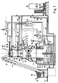
- the shredding device shown in FIG. 1 with all the auxiliary units required for its operation is mounted on a base 1.
- the centerpiece is an airtight work space 2, within which comminution tools 3 are arranged.
- the shredding tools 3 are driven by an electric motor and here comprise two intermeshing cutting drums which can be rotated about their longitudinal axis.
- a plurality of inlet openings 4 are arranged, which open into the working space 2. All inlet openings 4 are connected to a common ring line 5, which leads around the working space 2. At one point, the ring line 5 is connected to a main supply line 6.
- the supply line 6 can be opened or shut off by means of a main solenoid valve 7.
- the main solenoid valve 7 is bridged by a bypass line 8, which can be opened or closed continuously by means of a secondary solenoid valve 9.
- the main supply line 6 is connected to a protective gas container 10, which contains nitrogen here. By opening the main solenoid valve 7 or the secondary solenoid valve 9, nitrogen flows from the container 10 via the main supply line 6, the ring line 5 and the inlet openings 4 into the working space 2.
- Both the drive of the shredding tools 3 and the solenoid valves 7 and 9 are connected to an electronic regulating and control unit 11 via electrical lines.
- An airtight lockable lock container 15 is formed between an upper lock slide 13 and a lower lock slide 14.
- the two lock slides 13 and 14 are hydraulically operated and are opened and closed alternately, controlled by the regulating and control unit 11.
- the end positions of the sluice gate are monitored by means of electrical limit switches 37 and 38.
- a hopper 16 made of stainless steel is placed on the lock 12.
- a conveyor device 17, which is also mounted on the base 1, serves to convey containers 18 to be removed - which here are metal pressure cans - from a storage container 19 into the hopper 16.
- a waste container 21 is provided as a collecting device for the liquid and solid components of the comminuted container 18, which stands on the base 1 below the waste shaft 20.
- the airtight connection between waste container 21 and waste shaft 20, or work space 2 is served by a hydraulically movable seal 22.
- the seal 22 is shown in its raised position in the drawing.
- Further inlets 23 for nitrogen are provided on the lock 12. These inlets 23 are connected to a second ring line 24 which leads around the lock 12 and is connected to the nitrogen tank 10 via a second supply line 25.
- the second supply line 25, controlled by the regulating and control unit 11, can be opened or shut off by means of a solenoid valve 26. When the solenoid valve 26 is open, nitrogen flows out of the nitrogen container 10 into the lock 12.
- An exhaust pipe 27 is connected to the side of the waste container 21, which continues inside the container and merges into a vertical perforated standpipe 28.
- the waste container 21 has additional inlets 29 on its outer wall. These additional inlets 29 are connected to the same nitrogen tank 10 via a third ring line 30 and a third supply line 31.
- the nitrogen supply is controlled by means of a further solenoid valve 32, which is arranged in the third supply line 31.
- the exhaust gas line 27 there is an explosion-protected exhaust gas fan 33, the electromotive drive of which, like the solenoid valve 32 for the third supply line 31, is connected to the regulating and control unit 11 via electrical lines.
- the exhaust gas line 27 is led upwards and ends in a flaring station 34.
- a pressure measuring device 35 for measuring the excess pressure therein is arranged in the working space 2.
- An oxygen measuring device 36 is installed in the exhaust line 27 immediately after it is led out of the waste container 21.
- the measuring devices 35 and 36 are also electrically connected to the regulating and control unit 11.
- an emergency feed for nitrogen which works independently of the main solenoid valve 7; this consists of an emergency feed line 39, which is connected to the nitrogen container 10 and has a relatively thick cross-section, which opens into the main supply line 6 behind the main solenoid valve 7 immediately before the ring line 4.
- a manually operated ball valve 40 is arranged in the emergency feed line 39.
- nitrogen must be removed from the nitrogen container 10 via the inlet openings 4 into the working space in sufficient quantities while the shredding tools 3, closed lock valve 13 and seal 22 are closed between the waste container 21 and the waste shaft 20 the further inlets 23 are pushed into the lock 12 and via the additional inlets 25 into the waste container 21.
- oxygen-containing air located in the device is removed via the exhaust line 27 in order to render the entire device inert.
- the residual oxygen content in the exhaust air is measured by means of the oxygen measuring device 36 in the exhaust line 27. If the oxygen content falls below a predetermined limit value, which is dependent on the lower explosion limit of the propellants and other residual products located in the containers 18, the device is ready for operation.
- the containers 18 to be removed are now conveyed upwards by the conveying device 17 from the storage container 19 and thrown into the filling funnel 16.
- the containers 18 collect on the closed upper lock slide 13.
- the lock slide 13 opens and the containers 18 fall onto the closed lower lock slide 14.
- the upper lock slide 13 closes, so that the lock container 15 is airtight.
- the conveying device 17 is switched off during the introduction of the collected amount into the lock 12.
- the lock container 15 is emptied by opening the lower lock slide 14, so that the containers 18 fall into the working space 2 and onto the running crushing tools 3.
- the small amount of nitrogen escaping into the lock 12 closed above is immediately replaced via the inlet openings 4 and the further inlets 23.
- the containers 18 are now gripped by the shredding tools 3 and torn.
- the resulting solid constituents in the form of metal splinters fall through the waste shaft 20 into the waste container 21.
- Any liquid contained in the containers 18 collects in a sump at the bottom of the waste container 21.
- the propellant gases escaping from the destroyed containers 18 and any gaseous residual products that may be present are sucked off by the exhaust fan 33 via the perforated standpipe 28 in the waste container 21 and the connected exhaust pipe 27 and burned in the flaring station 34.
- the conveying device 17 has thrown a further predetermined amount of containers 18 to be removed into the filling funnel 16.
- the process described is repeated cyclically.
- the timed, alternating closing of the two gate valves 13, 14 and the constant flow of nitrogen while maintaining a slight excess pressure within the working space 2 ensures that the Destruction of the container 18 by the crushing tools 3 always takes place under an inert nitrogen atmosphere. Any risk of explosion is thus excluded.
- the removal process is interrupted, the crushing tools 3 are switched off and the seal 22 is raised, so that an empty waste container 21 can be placed under the full one. After the seal 22 is lowered and the purge device is again purged with nitrogen as described above, waste disposal can continue.
- the entire device is kept under nitrogen via the emergency feed line 39 with the ball valve 40 open.
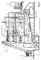
- FIG. 1 An alternative embodiment of the comminution device is shown in FIG.
- the waste container 21 of FIG. 1 is replaced by another collecting device, which essentially consists of a tube chain conveyor 41, a liquid container 42 and a solid container 43.
- the tube chain conveyor 41 has a conveyor tube 44 arranged obliquely upwards in the conveying direction, with an inlet shaft 45 adjoining the working space 2 and an ejection shaft 46 at its opposite end.
- a chain 47 runs around the inside of the conveyor tube 44, to which conveyor disks 48 are fastened at regular intervals.
- the delivery pipe 44 (cf. FIG. 2) is connected to the work space 2 in an airtight manner via the inlet shaft 45.
- a support structure 50 and a support 51 support the tube chain conveyor 41 with respect to the base 1 and thus simultaneously carry the weight of the entire comminution device.
- the conveyor tube 44 has an oval cross section in the area of the inlet shaft 45, which tapers in height towards the discharge shaft 46 and merges into a round cross section corresponding to the diameter of the conveyor disks 48.
- a plurality of flexible wipers 59 are attached above the conveyor disks 48.
- the delivery pipe 44 has a lower sieve plate element, through the holes of which liquid components of the comminuted container 18 can flow into a collecting trough 43 arranged underneath.
- an essentially identical upper sieve plate element 54 is provided.
- a drainage channel 55 runs below and parallel to the conveying pipe 44. With its lower end, the drainage channel 55 opens into the collecting trough 53.
- the liquid container 42 is connected to the collecting trough 53 via a manually operated ball valve 56.
- the solid and liquid constituents of the containers 18 comminuted by the comminution tools 3 in the work space 2 fall through the inlet shaft 45 from above into the conveying pipe 44 between the conveying discs 48. Most of the liquid flows immediately through the lower sieve plate element 52 and the collecting pan 53 into the liquid container 42 underneath.
- the solid components are gripped by the conveyor disks 48 and conveyed obliquely upward within the conveyor tube 44. Any liquid residues still adhering pass through the holes in the upper sieve plate element 54 into the drainage channel 55 and also flow into the collecting trough 53 or the liquid container 42.
- the dry solid constituents fall through the discharge chute 46 into the solid container 43 below.
- the liquid and Solid components of the comminuted containers 18 thus take place continuously through the tube chain conveyor 41, with a separation of solid and liquid components taking place at the same time.
- a full liquid container 42 can be exchanged for an empty container;
- the solid container 43 connected to the ejection chute 46 during operation can be easily replaced.
- the device shown in FIG. 2 works exactly like the first described device according to FIG. 1.
- Working space 2 the interior of the tube chain conveyor 41, liquid container 42 and solid container 43 form an airtight unit from the environment during the shredding process, so that no pollutants can escape to the outside.
- the lower part of the working space 2 the interior of the tube chain conveyor 41 and the two containers 42 and 43 are each connected via separate lines to an exhaust gas collecting line 57 which is connected to the exhaust gas line 27.
- both the tube chain conveyor 41 and the solids container 43 are connected to an additional supply line 58 for nitrogen.
- the nitrogen supply is controlled by means of the further solenoid valve 32, which is arranged in this additional supply line 58.
Abstract
Description
Die Erfindung betrifft eine Vorrichtung zum Zerkleinern und Beseitigen von unter Druck stehenden Metalldosen, welche Treibmittel und/oder leicht brennbare Restprodukte in flüssiger oder fester Form enthalten, mit einem Arbeitsraum, in dem motorgetriebene Zerkleinerungswerkzeuge angeordnet sind.The invention relates to a device for crushing and removing metal cans under pressure, which contain propellants and / or easily flammable residual products in liquid or solid form, with a work space in which motor-driven crushing tools are arranged.
Unter dem Druck eines Treibmittels stehende Metallbehälter sind weit verbreitet, beispielsweise in Form von Spraydosen. Häufig enthalten die Dosen leicht brennbare oder giftige, jedenfalls umweltgefährdende Produkte in flüssiger, fester oder gasförmiger Form. Derartige Behälter können deshalb nicht einfach wie gewöhnlicher Hausmüll deponiert werden, sondern sind einer gesonderten Abfallbeseitigung zuzuführen. Dabei müssen die Behälter zerkleinert werden, einmal um das darin enthaltene restliche Treibmittel und gegebenenfalls die Restprodukte aufzufangen und so eine ordnungsgemäße Entsorgung zu gewährleisten, zum anderen, um die Metalle, aus welchen die Behälter meistens gefertigt sind, als Recycling-Material wieder dem Rohstoffkreislauf zuzuführen.Metal containers under the pressure of a blowing agent are widespread, for example in the form of spray cans. The cans often contain highly flammable or toxic, at least environmentally hazardous products in liquid, solid or gaseous form. Such containers can therefore not simply be disposed of like normal household waste, but must be disposed of separately. The containers must be shredded, on the one hand to collect the residual propellant and possibly the residual products contained therein and thus ensure proper disposal, and on the other hand to recycle the metals from which the containers are mostly made as recycling material .
Bei der mechanischen Zerkleinerung von nicht vollständig entleerten Metalldosen besteht Explosionsgefahr, insbesondere wenn die Reste leichtentzündliche Bestandteile enthalten. Besonders problematisch ist die Beseitigung kompletter Fehlchargen gefüllter, unter hohem Druck stehender Dosen bzw. überlagerter Produkte.When comminuting metal cans that are not completely empty, there is a risk of explosion, especially if the residues contain highly flammable components. The removal of complete faulty batches of filled, high-pressure cans or superimposed products is particularly problematic.
Aus der US-PS 4 356 981 ist eine Vorrichtung zur Beseitigung von Behältern, welche Aerosole oder Treibmittel, entflammbare Gase oder giftige Chemikalien enthalten, bekannt. Die zu beseitigenden Behälter werden in einem Shredder zerstört; die Restbestandteile fallen anschließend nach unten auf eine Fördereinrichtung mit einem perforierten Förderband. Die Fördereinrichtung ist innerhalb eines im wesentlichen nach außen abgedichteten Gehäuse angeordnet, durch welches eine Luftstromung geleitet wird. Die flüssigen Restbestandteile tropfen durch die Löcher im Förderband nach unten ab und werden in einer darunter liegenden Wanne aufgefangen und über einen Flüssigkeits-Auslaß entleert. Die gasförmigen Bestandteile werden, zusammen mit der in das Gehäuse eingeleiteten Luft, über eine Absaugöffnung mittels eines Unterdruckgebläses kontrolliert abgeführt. Die mechanische Zerkleinerung der Behälter selbst geschieht jedoch nach wie vor in einer Atmosphäre, welche Sauerstoff enthält. Insbesondere Behälter, welche leicht entzündliche Bestandteile enthalten, können deshalb mit dieser vorbekannten Vorrichtung nicht gefahrlos zerkleinert bzw. beseitigt werden.From US Pat. No. 4,356,981 a device for the removal of containers which contain aerosols or propellants, flammable gases or toxic chemicals is known. The containers to be removed are destroyed in a shredder; the remaining components then fall down onto a conveyor with a perforated conveyor belt. The conveyor is arranged within a housing which is essentially sealed to the outside and through which an air flow is conducted. The liquid residues drip down through the holes in the conveyor belt and become in one below lying tub collected and emptied through a liquid outlet. The gaseous components, together with the air introduced into the housing, are discharged in a controlled manner via a suction opening by means of a vacuum blower. However, the mechanical shredding of the containers themselves still takes place in an atmosphere that contains oxygen. In particular, containers which contain highly flammable constituents can therefore not be safely comminuted or removed with this previously known device.
Aufgabe vorliegender Erfindung ist es somit, eine verbesserte Vorrichtung zur gefahrlosen und umweltfreundlichen Zerkleinerung und Beseitigung großer Mengen von unter Druck stehenden Metalldosen, welche Treibmittel und/oder Restprodukte enthalten, zu schaffen.The object of the present invention is therefore to provide an improved device for the safe and environmentally friendly comminution and removal of large amounts of pressurized metal cans which contain propellants and / or residual products.
Bei der Lösung dieser Aufgabe wird ausgegangen von einer Vorrichtung zum Zerkleinern von Behältern der eingangs genannten Art; gelöst wird die Aufgabe dadurch, daß der Arbeitsraum luftdicht abgeschlossen ist, daß darin während des Betriebs ein leichter Überdruck aufgebaut werden kann, daß in den Arbeitsraum eine Einlaßöffnung für Stickstoff mündet, ferner über dem Arbeitsraum eine Schleuse angeordnet ist, welche einen oberen und einen unteren Schleusenschieber sowie einen von diesen luftdicht abschließbaren Schleusenbehälter umfaßt, daß ein Fülltrichter auf die Schleuse aufgesetzt ist und eine Fördereinrichtung zum kontinuierlichen Einfüllen von Behältern in den Fülltrichter vorgesehen ist, daß weiter eine Auffangvorrichtung für die Bestandteile der zerkleinerten Behälter vorgesehen ist, welche sich luftdicht an den Arbeitsraum anschließt, und mit dem Arbeitsraum eine Abgasleitung zur Abführung der bei der Zerkleinerung freigesetzten Gase in Verbindung steht, und daß schließlich eine Sauerstoff-Meßeinrichtung zur Überwachung des Sauerstoffgehalts in der Abluft vorgesehen ist.In solving this problem it is assumed that there is a device for crushing containers of the type mentioned at the beginning; The object is achieved in that the work space is sealed airtight, that a slight positive pressure can be built up during operation, that an inlet opening for nitrogen opens into the work space, and a lock is arranged above the work space, which has an upper and a lower one Lock valve and an airtight lockable lock container includes that a hopper is placed on the lock and a conveyor for continuously filling containers into the hopper is provided, that a collecting device for the components of the shredded container is further provided, which is airtight to the Connects work space, and with the work space an exhaust pipe for discharging the gases released during comminution is connected, and that finally an oxygen measuring device is provided for monitoring the oxygen content in the exhaust air.
Während des Betriebs herrscht im Arbeitsraum der erfindungsgemäß ausgebildeten Vorrichtung eine inerte Schutzgas-Atmosphäre mit leichtem Überdruck gegenüber der Umgebung. Selbst unter hohem Innendruck stehende Metalldosen mit hochbrennbarem Inhalt können so trotz kaum vermeidbarer Funkenbildung gefahrlos mechanisch zerkleinert werden. Die inerte Schutzgas-Atmosphäre verhindert zuverlässig jede Gefahr einer Selbstentzündung des schlagartig aus den zerplatzenden Dosen entweichenden Inhalts.During operation, an inert protective gas atmosphere prevails in the working space of the device designed according to the invention with a slight excess pressure relative to the surroundings. Even metal cans with highly flammable contents under high internal pressure can be mechanically shredded without risk, despite the inevitable formation of sparks. The inert protective gas atmosphere reliably prevents any risk of spontaneous combustion of the contents that suddenly escape from the bursting cans.
Als Schutzgas kann Stickstoff, Kohlendioxid oder ein anderes Inertgas verwendet werden.Nitrogen, carbon dioxide or another inert gas can be used as the protective gas.
Die geringen, beim zyklischen Eindringen von neuen Behältern in die Schleuse entweichenden Mengen von Schutzgas werden über die in den Arbeitsraum mündenden Einlaßöffnungen fortwährend ersetzt. Die bei der Zerkleinerung anfallenden festen Bestandteile der Behälter fallen nach unten in die Auffangvorrichtung; eventuell vorhandene flüssige Bestandteile sammeln sich ebenfalls in der Auffangvorrichtung. Wertstoffe können so wiedergewonnen werden. Gasförmige Bestandteile werden über die Abgasleitung abgeführt und einer gezielten Entsorgung zugeleitet. Die mit der Erfindung geschaffene Vorrichtung erlaubt somit eine völlig gefahrlose und umweltfreundliche Beseitigung von Metallbehältern mit kritischem Inhalt, wobei durch das Zusammenwirken von Fördereinrichtung, Fülltrichter und Schleusenschiebern auch größere Mengen von Dosen in einem kontinuierlichen Prozeß verarbeitet werden können.The small amounts of protective gas escaping when new containers enter the lock cyclically are continuously replaced via the inlet openings opening into the work area. The solid constituents of the containers that result from the shredding fall downwards into the collecting device; any liquid components that may be present also collect in the collecting device. In this way, valuable materials can be recovered. Gaseous constituents are discharged via the exhaust pipe and sent for targeted disposal. The device created with the invention thus allows a completely safe and environmentally friendly removal of metal containers with critical contents, whereby larger amounts of cans can be processed in a continuous process by the interaction of the conveyor, hopper and sluice gate.
Bei einer bevorzugten Ausführungsform der Erfindung sind die Einlaßöffnungen für Schutzgas oberhalb der Zerkleinerungswerkzeuge angeordnet. Nach oben in die Schleuse entwichener Stickstoff kann so sehr schnell ersetzt werden. Zweckmäßigerweise stehen die Einlaßöffnungen mit einer Ringleitung in Verbindung, welche um den Arbeitsraum herumführt. An diese Ringleitung läßt sich eine zentrale Hauptversorgungsleitung anschließen. Gesteuert von einem Hauptmagnetventil lassen sich schnell große Mengen von Schutzgas über diese Hauptversorgungsleitung, die Ringleitung und die Einlaßöffnungen in den Arbeitsraum einleiten. Bevor mit der Zerkleinerung von Behältern begonnen wird, muß nämlich die in der Vorrichtung befindliche sauerstoffhaltige Luft herausgedrückt werden. Erst wenn innerhalb des Arbeitsraums die untere Explosionsgrenze unterschritten ist, kann die Zerkleinerung beginnen.In a preferred embodiment of the invention, the inlet openings for protective gas are arranged above the comminution tools. Nitrogen escaping up into the lock can be replaced very quickly. The inlet openings are expediently connected to a ring line which leads around the work space. A central main supply line can be connected to this ring line. Controlled by a main solenoid valve, large amounts of shielding gas can quickly be introduced into the work space via this main supply line, the ring line and the inlet openings. Before the shredding of containers is started, the oxygen-containing air in the device must be pressed out. The comminution can only begin when the lower explosion limit is undershot within the work area.
Während des normalen Betriebs bleibt das Hauptmagnetventil in der Hauptversorgungsleitung geschlossen. Um dennoch geringe Schutzgas-Mengen ergänzen zu können, ist bei einer vorteilhaften Weiterbildung der Zerkleinerungsvorrichtung eine Bypass-Leitung vorgesehen, welche das Hauptmagnetventil überbrückt. Die Regelung des Schutzgas-Stroms ist so, daß stets ein leichter Überdruck aufrechterhalten wird; sie erfolgt zweckmäßigerweise mittels eines Nebenmagnetventils innerhalb der Bypass-Leitung.During normal operation, the main solenoid valve in the main supply line remains closed. In order to be able to add small amounts of shielding gas nevertheless, a bypass line is provided in an advantageous development of the comminution device, which bypasses the main solenoid valve. The regulation of the protective gas flow is such that a slight overpressure is always maintained; it is expediently carried out by means of a secondary solenoid valve within the bypass line.
Die den Schleusenbehälter abschließenden Schleusenschieber sind bevorzugt pneumatisch, hydraulisch oder elektrisch betätigt. Die Endstellungen der Schleusenschieber können mittels elektrischer Endschalter überwacht werden. Ein nicht ordnungsgemäßes Verschließen der Schleuse kann so erkannt und die Vorrichtung abgeschaltet werden.The lock slides closing the lock container are preferably operated pneumatically, hydraulically or electrically. The end positions of the sluice gate can be monitored using electrical limit switches. Improper closing of the lock can thus be recognized and the device can be switched off.
Ferner ist es vorteilhaft, wenn an der Schleuse weitere Einlässe für Schutzgas vorgesehen sind, über die Schutzgas direkt auch in diesen Raum eingeleitet werden kann. Die Entstehung eines explosionsfähigen Gemischs kann so auch dann verhindert werden, wenn aus den Behältern beim Einbringen in die Schleuse Treibgas oder Restprodukte entweichen. Zweckmäßigerweise werden diese weiteren Einlässe über eine zweite Ringleitung, die um die Schleuse herumführt, mit Schutzgas versorgt.It is also advantageous if further inlets for protective gas are provided on the lock, through which protective gas can also be introduced directly into this space. The formation of an explosive mixture can thus also be prevented if propellant gas or residual products escape from the containers when they are introduced into the lock. These further inlets are expediently supplied with protective gas via a second ring line which leads around the lock.
Der Erhöhung der Betriebssicherheit dem Vorrichtung dient es, wenn im Arbeitsraum eine Druckmesseinrichtung zur Überwachung des Schutzgas-Druckes vorgesehen ist.It increases the operational safety of the device if a pressure measuring device for monitoring the protective gas pressure is provided in the work area.
Die vorzugsweise in der Abgasleitung vorgesehene Sauerstoff-Meßeinrichtung dient in erster Linie dazu, beim Durchspülen der Vorrichtung mit Schutzgas vor der Inbetriebnahme der Anlage anzuzeigen, daß keine sauerstoffhaltige Luft mehr im Arbeitsraum vorhanden ist. Die Meßeinrichtung zeigt jedoch auch während des Betriebs eventuell trotz des Überdrucks der Vorrichtung eingedrungenen Sauerstoff an. In Verbindung mit einer elektronischen Regel- und Steuereinheit kann der Zerkleinerungs- und Beseitungsprozeß dann sofort automatisch unterbrochen oder mit Schutzgas geflutet werden.The oxygen measuring device, which is preferably provided in the exhaust gas line, serves primarily to indicate when flushing the device with protective gas before starting up the system that there is no longer any oxygen-containing air in the work space. However, the measuring device also shows oxygen that may have penetrated during operation despite the overpressure of the device. In conjunction with an electronic regulating and control unit, the shredding and disposal process can then be automatically interrupted immediately or flooded with protective gas.
Die Abführung der gasförmigen Bestandteile aus dem Arbeitsraum wie auch aus der Auffangvorrichtung für die Bestandteile der zerkleinerten Behälter kann durch die Anordnung eines Absaugventilators in der Abgasleitung beschleunigt werden.The removal of the gaseous constituents from the work space as well as from the collecting device for the constituents of the comminuted containers can be accelerated by the arrangement of a suction fan in the exhaust pipe.
Zur ordnungsgemäßen Entsorgung der freiwerdenden Abgase kann an das Ende der Abgasleitung eine Abfackelstation oder eine thermische Verbrennungseinrichtung angeschlossen sein. Ist eine Verbrennung der Gase aufgrund ihrer chemischen Zusammensetzung nicht möglich, so kann statt dessen eine Kondensationsvorrichtung mit anschließender Einrichtung zur fraktionierten Destillation oder eine Abfüllvorrichtung für die kondensierten Gase am Ende der Abgasleitung angeordnet sein.A flaring station or a thermal combustion device can be connected to the end of the exhaust pipe for proper disposal of the released gases. If combustion of the gases is not possible due to their chemical composition, a condensation device with subsequent device for fractional distillation or a filling device for the condensed gases can be arranged at the end of the exhaust pipe instead.
Auch bei längerem Stillstand, beispielsweise über das Wochenende, muß die Zerkleinerungsvorrichtung unter Schutzgas gehalten werden, um mit Sicherheit Glimmbrände zu vermeiden. Hierzu ist zweckmäßigerweise eine unabhängige Noteinspeiseleitung für Schutzgas vorgesehen, welche hinter dem Hauptmagnetventil in die Hauptversorgungsleitung mündet. Damit die Schutzgaszufuhr auch bei abgeschaltetem oder ausgefallenem elektrischen Strom nicht unterbrochen wird, empfiehlt sich der Einbau eines handbetätigten Ventils in diese Noteinspeiseleitung.Even in the event of a long standstill, for example over the weekend, the shredding device must be kept under protective gas in order to avoid smoldering fires with certainty. For this purpose, an independent emergency feed line for protective gas is expediently provided, which opens into the main supply line behind the main solenoid valve. To ensure that the shielding gas supply is not interrupted even when the electrical power is switched off or has failed, the installation of a manually operated valve in this emergency feed line is recommended.
Bei einer Ausführungsform der erfindungsgemäßen Vorrichtung besteht die Auffangvorrichtung für die Bestandteile der zerkleinerten Behälter aus einem Abfallcontainer, der unter dem Arbeitsraum angeordnet ist und mit diesem luftdicht in Verbindung steht. Ist zwischen dem unteren Ende des Arbeitsraums und diesem Abfallcontainer eine pneumatisch, hydraulisch oder elektrisch hochfahrbare Abdichtung vorgesehen, so läßt sich ein voller Container schnell und einfach gegen einen leeren austauschen.In one embodiment of the device according to the invention, the collecting device for the components of the comminuted containers consists of a waste container which is arranged under the work space and is connected to it in an airtight manner. If a pneumatically, hydraulically or electrically raised seal is provided between the lower end of the work area and this waste container, a full container can be quickly and easily exchanged for an empty one.
Für eine schnelle und vollständige Spülung der gesamten Vorrichtung mit Schutzgas vor der Inbetriebnahme der Zerkleinerungswerkzeuge ist es von Vorteil, wenn auch der Abfallcontainer eigene Zusatz-Einlässe für Schutzgas aufweist.For a quick and complete purging of the entire device with protective gas before the comminution tools are put into operation, it is advantageous if the waste container also has its own additional inlets for protective gas.
Bevorzugt wird ferner eine Ausführung, bei der innerhalb des Abfallcontainers ein perforiertes Standrohr angeordnet ist, welches mit der Abgasleitung in Verbindung steht. Die Außenwand dieses Standrohres hält die festen Bestandteile zurück, während Gase durch die Löcher in das Standrohr und von dort in die Abgasleitung gesaugt werden.Also preferred is an embodiment in which a perforated standpipe is arranged inside the waste container and is connected to the exhaust pipe. The outer wall of this standpipe retains the solid components, while gases are sucked through the holes in the standpipe and from there into the exhaust pipe.
Bei einer alternativen Ausführungsform der Zerkleinerungsvorrichtung besteht die Auffangvorrichtung für die Bestandteile der zerkleinerten Behälter im wesentlichen aus einem Rohrkettenförderer mit einem an den Arbeitsraum anschließenden Einlaufschacht, einem Förderrohr, das wenigstens ein Siebbodenelement aufweist, mit innerhalb des Förderrohrs an einer umlaufenden Kette geführten Förderscheiben, einer unterhalb des Siebbodenelements angeordneten Auffangwanne und mit einem Auswurfschacht, und umfaßt ferner einen an die Auffangwanne angeschlossenen Flüssigkeitsbehälter für flüssige Restprodukte sowie einen unter dem Auswurfschacht angeordneten Feststoffbehälter für feste Bestandteile. Die zerkleinerten Blech- und Kunststoffbestandteile der zu beseitigenden Behälter fallen mitsamt den freigesetzten Lösemitteln bzw. Restsprodukten in den Einlaufschacht des Rohrkettenförderers und von dort zwischen die Förderscheiben. Durch die Öffnungen im Siebbodenelement des Förderrohrs laufen die flüssigen Bestandteile nach unten in die Auffangwanne ab und fließen in den darunter stehenden Flüssigkeitsbehälter. Die festen Bestandteile dagegen werden durch die Förderscheiben innerhalb des Förderrohrs in Richtung des Auswurfschachts gefördert, durch welchen sie in den darunter stehenden Feststoffbehälter fallen. Infolge des Transports über das am Anfang des Förderrohrs vorgesehenen Siebbodenelement werden die bei der Zerkleinerung anfallenden Feststoffe von den freigesetzten Flüssigkeiten automatisch getrennt. Eine Rückgewinnung der oft wertvollen flüssigen Wirkstoffe und Lösemittel ist somit möglich. Ebenso wie bei der einfacheren Ausführungsform mit als untergestelltem Abfallcontainer ausgebildeter Auffangvorrichtung werden die freigesetzten Gase über die Abgasleitung, welche mit dem Arbeitsraum in Verbindung steht, abgesaugt und der Entsorgung zugeführt. Ein weiterer Vorteil der so ausgebildeten Auffangvorrichtung besteht darin, daß die Zerkleinerungsprodukte kontinuierlich aus dem Arbeitsraum entfernt werden können.In an alternative embodiment of the comminution device, the collecting device for the components of the comminuted containers essentially consists of a tube chain conveyor with an inlet shaft adjoining the work space, a conveyor tube which has at least one sieve bottom element, with conveyor disks guided inside the conveyor tube on a circulating chain, one below of the sieve bottom element arranged collecting tray and with an ejection chute, and further comprises a liquid container connected to the collecting trough for liquid residual products and a solid container arranged under the ejection chute for solid components. The shredded sheet metal and plastic components of the containers to be removed, together with the released solvents or residual products, fall into the inlet shaft of the tube chain conveyor and from there between the conveyor disks. The liquid components run down through the openings in the sieve bottom element of the conveyor tube into the collecting trough and flow into the liquid container underneath. The solid components, on the other hand, are conveyed by the conveyor disks within the conveyor tube in the direction of the discharge chute, through which they fall into the solid container below. As a result of the transport via the sieve plate element provided at the beginning of the conveyor tube, the solids obtained during the comminution are automatically separated from the released liquids. It is therefore possible to recover the often valuable liquid active ingredients and solvents. Just as in the simpler embodiment with a collecting device designed as a subordinate waste container, the released gases are passed through the exhaust pipe, which is connected to the work space stands, suctioned off and disposed of. Another advantage of the collecting device designed in this way is that the comminution products can be removed continuously from the work space.
In bevorzugter Ausführung ist das Förderrohr in Förderrichtung schräg nach oben angeordnet und verjüngt sich in der Höhe zum Auswurfschacht hin. Hierdurch wird ein Verklemmen des Förderguts zwischen den Förderscheiben im Bereich des Einlaufschachts vermieden. Eine zusätzliche Hilfe zur Vermeidung von Verklemmungen des Förderguts bieten mehrere, an der Oberseite des Förderrohrs innen angebrachte, flexible Abstreifer zur Einebnung des Förderguts zwischen die Förderscheiben.In a preferred embodiment, the conveying pipe is arranged obliquely upward in the conveying direction and tapers in height towards the discharge chute. This prevents the material to be jammed between the conveyor disks in the area of the inlet shaft. Additional help to avoid jamming of the conveyed goods is provided by several flexible scrapers attached to the inside of the top of the conveying pipe for leveling the conveyed goods between the conveyor disks.
Zweckmäßigerweise sind die im Förderrohr umlaufenden Förderscheiben an ihrem Umfang mit Ausnehmungen versehen, sodaß die an den zerkleinerten Bestandteilen anhaftenden abtropfenden Flüssigkeitsreste am Boden des Förderrohrs nach unten über das Siebbodenelement in die darunter angeordnete Auffangwanne ablaufen können. Anstelle einer umlaufenden Kette mit Förderscheiben kann auch eine mit Bohrungen versehene Förderschnecke Verwendung finden.Advantageously, the circumferential conveyor disks in the conveyor tube are provided with recesses on their circumference, so that the dripping liquid residues adhering to the comminuted constituents can drain downward at the bottom of the conveyor tube via the sieve bottom element into the collecting trough arranged below. Instead of a revolving chain with conveyor disks, a screw conveyor with holes can also be used.
In vorteilhafter Weiterbildung der Erfindung weist das Förderrohr im Bereich des Auswurfschachts, also an seinem oberen Ende, ein weiteres Siebbodenelement auf und ist unterhalb des Förderrohrs und parallel zu diesem eine Ablaufrinne angeordnet, welche in die Auffangwanne mündet. Eventuell bis kurz vor den Auswurfschacht mitgeführte Flüssigkeitsreste können so über das weitere Siebbodenelement in die unter dem Förderrohr verlaufende Ablaufrinne abtropfen, von wo sie in die Auffangwanne und von dort ebenfalls in den angeschlossenen Flüssigkeitsbehälter gelangen. Die schließlich in den Feststoffbehälter fallenden festen Bestandteile sind nach dem Durchlaufen des Förderrohrs nahezu vollständig abgetrocknet.In an advantageous development of the invention, the delivery pipe has a further sieve plate element in the region of the discharge chute, that is to say at its upper end, and a drainage channel is arranged below the delivery pipe and parallel to it, which opens into the collecting trough. Any liquid residues carried up to shortly before the discharge chute can drip over the other sieve plate element into the drainage channel running under the conveyor pipe, from where they get into the collecting trough and from there also into the connected liquid container. The solid constituents that finally fall into the solids container are almost completely dry after passing through the delivery pipe.
Um die gesamte, gegenüber der Umgebung luftdicht abgeschlossene Anlage stets von den bei der Zerkleinerung der Behälter freigesetzten Gasen frei zu halten, ist es ferner von Vorteil, daß das Förderrohr des Rohrkettenförderers, der Flüssigkeitsbehälter sowie der Feststoffbehälter jeweils direkt an die Abgasleitung angeschlossen sind. Ebenso läßt sich das vor der Inbetriebnahme erforderliche Durchspülen des Inneren der Anlage mit Schutzgas beschleunigen, wenn Rohrkettenförderer und Feststoffbehälter über separate Versorgungsleitungen an die Schutzgaszufuhr angeschlossen sind.In order to always keep the entire system, which is hermetically sealed from the environment, free of the gases released during comminution of the containers, it is also advantageous that the conveyor tube of the tube chain conveyor, the liquid container and the solids container are each connected directly to the exhaust pipe. It is also possible to accelerate the purging of the interior of the system with protective gas, which is required before commissioning, if the tube chain conveyor and the solids container are connected to the protective gas supply via separate supply lines.
Zwei Ausführungsbeispiele der Erfindung werden nachstehend anhand der beigefügten Zeichnungen näher erläutert. Es zeigen:
- Fig. 1 eine Vorrichtung zum Zerkleinern von Behältern mit unter dem Arbeitsraum angeordnetem Abfallcontainer, in schematischer Darstellung;
- Fig. 2 eine zweite Ausführungsform der Zerkleinerungsvorrichtung, bei der an Stelle des Abfallcontainers ein Rohrkettenförderer, ein Flüssigkeitsbehälter und ein Feststoffbehälter vorgesehen ist, ebenfalls schematisch.
- Fig.3 eine Förderscheibe des Rohrkettenförderers gemäß Figur 2, in perspektivischer Darstellung.
- Figure 1 shows a device for crushing containers with a waste container arranged under the work space, in a schematic representation.
- Fig. 2 shows a second embodiment of the shredding device, in which a tube chain conveyor, a liquid container and a solid container is provided instead of the waste container, also schematically.
- 3 shows a conveyor disk of the tube chain conveyor according to FIG. 2, in a perspective view.
Die in Figur 1 mit allen für ihren Betrieb erforderlichen Nebenaggregaten dargestellte Zerkleinerungsvorrichtung ist auf einem Sockel 1 montiert. Kernstück ist ein luftdicht abgeschlossener Arbeitsraum 2, innerhalb dem Zerkleinerungswerkzeuge 3 angeordnet sind. Die Zerkleinerungswerkzeuge 3 sind elektromotorisch angetrieben und umfassen hier zwei um ihre Längsachse drehbare, ineinandergreifende Schneidtrommeln.The shredding device shown in FIG. 1 with all the auxiliary units required for its operation is mounted on a base 1. The centerpiece is an
Oberhalb der Zerkleinerungswerkzeuge 3 sind mehrere Einlaßöffnungen 4 angeordnet, welche in den Arbeitsraum 2 münden. Alle Einlaßöffnungen 4 stehen mit einer gemeinsamen Ringleitung 5 in Verbindung, welche um den Arbeitsraum 2 herumführt. An einer Stelle ist die Ringleitung 5 an eine Hauptversorgungsleitung 6 angeschlossen. Mittels eines Hauptmagnetventils 7 läßt sich die Versorgungsleitung 6 öffnen oder absperren. Das Hauptmagnetventil 7 ist durch eine Bypass-Leitung 8 überbrückt, die sich mittels eines Nebenmagnetventils 9 kontinuierlich öffnen, beziehungsweise schließen läßt. Die Hauptversorgungsleitung 6 steht mit einem Schutzgas-Behälter 10 in Verbindung, der hier Stickstoff enthält. Durch Öffnen des Hauptmagnetventils 7, beziehungsweise des Nebenmagnetventils 9 strömt Stickstoff vom Behälter 10 über die Hauptversorgungsleitung 6, die Ringleitung 5 und die Einlaßöffnungen 4 in den Arbeitsraum 2 ein.Above the crushing
Sowohl der Antrieb der Zerkleinerungswerkzeuge 3 wie auch die Magnetventile 7 und 9 sind über elektrische Leitungen mit einer elektronischen Regel- und Steuerungseinheit 11 verbunden.Both the drive of the
Über dem Arbeitsraum 2 ist eine insgesamt mit 12 bezeichnete Schleuse angeordnet. Zwischen einem oberen Schleusenschieber 13 und einem unteren Schleusenschieber 14 ist ein luftdicht abschließbarer Schleusenbehälter 15 ausgebildet. Die beiden Schleusenschieber 13 und 14 sind hydraulisch betätigt und werden abwechselnd, gesteuert von der Regel- und Steuerungseinheit 11, geöffnet und geschlossen. Die Endstellungen der Schleusenschieber werden mittels elektrischer Endschalter 37 und 38 überwacht.Above the
Auf die Schleuse 12 ist ein Fülltrichter 16 aus Edelstahl aufgesetzt. Eine ebenfalls auf den Sockel 1 montierte Fördereinrichtung 17 dient zur Förderung von zu beseitigenden Behältern 18 - welche hier Druckdosen aus Metall sind - aus einem Vorlagebehälter 19 in den Fülltrichter 16.A
An seinem unteren Ende geht der Arbeitsraum 2 in einen Abfallschacht 20 über. Als Auffangvorrichtung für die flüssigen und festen Bestandteile der zerkleinerten Behälter 18 ist ein Abfallcontainer 21 vorgesehen, der unterhalb des Abfallschachts 20 auf dem Sockel 1 aufsteht. Der luftdichten Verbindung zwischen Abfallcontainer 21 und Abfallschacht 20, beziehungsweise Arbeitsraum 2, dient eine hydraulisch hochfahrbare Abdichtung 22. In der Zeichnung ist die Abdichtung 22 in ihrer hochgefahrenen Stellung dargestellt. An der Schleuse 12 sind weitere Einlässe 23 für Stickstoff vorgesehen. Diese Einlässe 23 stehen mit einer um die Schleuse 12 herumführenden zweiten Ringleitung 24 in Verbindung, die über eine zweite Versorgungsleitung 25 an den Stickstoff-Behälter 10 angeschlossen ist. Mittels eines Magnetventils 26 läßt sich die zweite Versorgungsleitung 25, gesteuert von der Regel- und Steuerungseinheit 11, öffnen oder absperren. Bei geöffnetem Magnetventil 26 strömt Stickstoff aus dem Stickstoff-Behälter 10 in die Schleuse 12.At its lower end, the
An dem Abfallcontainer 21 ist seitlich eine Abgasleitung 27 angeschlossen, welche sich innerhalb des Containers fortsetzt und in ein vertikales perforiertes Standrohr 28 übergeht. Der Abfallcontainer 21 weist an seiner Außenwand Zusatz-Einlässe 29 auf. Über eine dritte Ringleitung 30 und eine dritte Versorgungsleitung 31 stehen diese Zusatz-Einlässe 29 mit dem gleichen Stickstoff-Behälter 10 in Verbindung. Die Stickstoff-Zufuhr wird mittels eines weiteren Magnetventils 32, welches in der dritten Versorgungsleitung 31 angeordnet ist, gesteuert.An
In der Abgasleitung 27 befindet sich ein explosionsgeschützter Abgasventilator 33, dessen elektromotorischer Antrieb, ebenso wie das Magnetventil 32 für die dritte Versorgungsleitung 31, über elektrische Leitungen mit der Regel- und Steuerungseinheit 11 verbunden ist. Die Abgasleitung 27 ist nach oben geführt und endet in einer Abfackelstation 34.In the
Im Arbeitsraum 2 ist eine Druckmeßeinrichtung 35 zur Messung des darin herrschenden Überdrucks angeordnet. In die Abgasleitung 27 ist unmittelbar nach deren Herausführung aus dem Abfallcontainer 21 eine Sauerstoff-Meßeinrichtungen 36 eingebaut. Die Meßeinrichtungen 35 und 36 sind ebenfalls elektrisch an die Regel- und Steuerungseinheit 11 angeschlossen.A
Es ist ferner eine unabhängig vom Hauptmagnetventil 7 arbeitende Noteinspeisung für Sticksktoff vorgesehen; diese besteht aus einer mit dem Stickstoff-Behälter 10 in Verbindung stehende Noteinspeiseleitung 39 mit relativ dickem Querschnitt, die hinter dem Hauptmagnetventil 7 unmittelbar vor der Ringleitung 4 in die Hauptversorgungsleitung 6 mündet. In der Noteinspeiseleitung 39 ist ein handbetätigtes Kugelhahnventil 40 angeordnet.There is also provided an emergency feed for nitrogen which works independently of the
Die vorstehend beschriebene Vorrichtung arbeitet wie folgt:The device described above works as follows:
Bevor mit der Zerkleinerung von zu beseitigenden Behältern 18 begonnen wird, muß bei laufenden Zerkleinerungswerkzeugen 3, geschlossenem Schleusenschieber 13 und zugefahrener Abdichtung 22 zwischen Abfallcontainer 21 und Abfallschacht 20 Stickstoff in ausreichender Menge aus dem Stickstoff-Behälter 10 über die Einlaßöffnungen 4 in den Arbeitsraum, über die weiteren Einlässe 23 in die Schleuse 12 und über die Zusatz-Einlässe 25 in den Abfallcontainer 21 gedrückt werden. Hierdurch wird in der Vorichtung befindliche, sauerstoffhaltige Luft über die Abgasleitung 27 entfernt, um die gesamte Vorrichtung zu inertisieren. Während dieses vorbereitenden Spülvorgangs wird der Restsauerstoffgehalt in der Abluft mittels der Sauerstoff-Meßeinrichtung 36 in der Abgasleitung 27 gemessen. Unterschreitet der Sauerstoffgehalt einen vorgegebenen Grenzwert, welcher abhängig ist von der unteren Explosionsgrenze der in den Behältern 18 befindlichen Treibmittel und sonstigen Restprodukte, so ist die Vorrichtung betriebsbereit.Before the shredding of
Bei geschlossenem Magnetventil 7 wird nun lediglich der Arbeitsraum 2 unter einem leichten Überdruck gehalten, wobei durch das geöffnete Nebenmagnetventil 9 und die Bypass-Leitung 8 eine wesentlich geringere Stickstoff-Menge durch die Einlaßöffnungen 4 strömt. Der herrschende Überdruck wird von der Druckmeßeinrichtung 35 laufend überwacht.When the
Gleichzeitig wird eine gedrosselte Menge von Stickstoff über das Magnetventil 26, die zweite Versorgungsleitung 25 und die zweite Ringleitung 24 in die Schleuse 12 geleitet. Dabei ist der obere Schleusenschieber 13 geschlossen, sodaß auch im Schleusenbehälter 15 eine inerte Stickstoff-Atmosphäre aufrecht erhalten wird.At the same time, a throttled amount of nitrogen is fed into the
Die zu beseitigenden Behälter 18 werden nun von der Fördereinrichtung 17 aus dem Vorlagebehälter 19 nach oben gefördert und in den Fülltrichter 16 eingeworfen. Die Behälter 18 sammeln sich auf dem geschlossenen oberen Schleusenschieber 13. Ist eine vorbestimmte Menge von Behältern 18 zusammengekommen, so öffnet der Schleusenschieber 13 und die Behälter 18 fallen auf den geschlossenen unteren Schleusenschieber 14. Anschließend schließt sich der obere Schleusenschieber 13, sodaß der Schleusenbehälter 15 luftdicht abgeschlossen ist. Während des Einbringens der gesammelten Menge in die Schleuse 12 ist die Fördereinrichtung 17 abgeschaltet.The
Im nächsten Verfahrensschritt wird der Schleusenbehälter 15 durch Öffnen des unteren Schleusenschiebers 14 entleert, sodaß die Behälter 18 in den Arbeitsraum 2 und auf die laufenden Zerkleinerungswerkzeuge 3 fallen. Die dabei in die oben geschlossene Schleuse 12 entweichende geringe Menge von Stickstoff wird sofort über die Einlaßöffnungen 4 und die weiteren Einlässe 23 ersetzt. Die Behälter 18 werden nun von den Zerkleinerungswerkzeugen 3 erfaßt und zerrissen. Die dabei anfallenden festen Bestandteile in Form von Metallsplittern fallen durch den Abfallschacht 20 in den Abfallcontainer 21. Eventuell in den Behältern 18 enthaltene Flüssigkeit sammelt sich in einem Sumpf am Boden des Abfallcontainers 21. Die aus den zerstörten Behältern 18 entweichenden Treibgase und gegebenenfalls vorhandene gasförmige Restprodukte werden über das perforierte Standrohr 28 im Abfallcontainer 21 und die angeschlossene Abgasleitung 27 vom Abgasventilator 33 abgesaugt und in der Abfackelstation 34 verbrannt.In the next process step, the
Zwischenzeitlich hat die Fördereinrichtung 17 eine weitere vorbestimmte Menge von zu beseitigenden Behältern 18 in den Fülltrichter 16 eingeworfen. Der beschriebene Vorgang wiederholt sich zyklisch. Das zeitlich aufeinander abgestimmte, abwechselnde Schließen der beiden Schleusenschieber 13, 14 und das ständige Nachströmen von Stickstoff unter Aufrechterhaltung eines leichten Überdrucks innerhalb des Arbeitsraums 2 gewährleistet, daß die Zerstörung der Behälter 18 durch die Zerkleinerungswerkzeuge 3 stets unter einer inerten Stickstoff-Atmosphäre stattfindet. Jegliche Explosionsgefahr ist somit ausgeschlossen. Ist der Abfallcontainer 21 mit festen Bestandteilen angefüllt, so wird der Beseitigungsprozeß unterbrochen, die Zerkleinerungswerkzeuge 3 abgeschaltet und die Abdichtung 22 hochgefahren, sodaß ein leerer Abfallcontainer 21 anstelle des vollen untergestellt werden kann. Nach dem Herabfahren der Abdichtung 22 und der erneuten, oben beschriebenen Spülung der Beseitigungsvorrichtung mit Stickstoff kann die Abfallbeseitigung fortgesetzt werden.In the meantime, the conveying
Bei längeren Stillstandszeiten wird die gesamte Vorrichtung über die Noteinspeiseleitung 39 bei geöffnetem Kugelhahnventil 40 unter Stickstoff gehalten.During longer downtimes, the entire device is kept under nitrogen via the
In Figur 2 ist eine alternative Ausführungsform der Zerkleinerungsvorrichtung dargestellt. Dabei ist der Abfallcontainer 21 von Figur 1 ersetzt durch eine andere Auffangvorrichtung, die im wesentlichen aus einem Rohrkettenförderer 41, einem Flüssigkeitsbehälter 42 und einem Feststoffbehälter 43 besteht. Der Rohrkettenförderer 41 weist ein in Förderrichtung schräg nach oben angeordnetes Förderrohr 44 auf, mit einem an den Arbeitsraum 2 anschließenden Einlaufschacht 45 und einem Auswurfschacht 46 an seinem gegenüberliegenden Ende. Im Innern des Förderrohrs 44 läuft eine Kette 47 um, an welcher in regelmäßigen Abständen Förderscheiben 48 befestigt sind.An alternative embodiment of the comminution device is shown in FIG. The
In Figur 3 ist eine einzelne dieser Förderscheiben 48 perspektivisch dargestellt. An ihrem Umfang ist die Förderscheibe 48 mit Ausnehmungen 49 versehen, sodaß größere Feststoffteile entlang der mit einem dicken Pfeil angegebenen Förderrichtung schräg nach oben transportiert werden; abtropfende Flüssigkeitsreste jedoch fließen entgegen der Förderrichtung zwischen den Ausnehmungen 49 und der Innenwand des Förderrohrs 44 hindurch schräg nach unten ab.In Figure 3, a single one of these
Das Förderrohr 44 (vgl. Fig. 2) ist über den Einlaufschacht 45 luftdicht mit dem Arbeitsraum 2 verbunden. Ein Tragwerk 50 und eine Stütze 51 stützen den Rohrkettenförderer 41 gegenüber dem Sockel 1 ab und tragen damit gleichzeitig das Gewicht der gesamten Zerkleinerungsvorrichtung.The delivery pipe 44 (cf. FIG. 2) is connected to the
Das Förderrohr 44 besitzt im Bereich des Einlaufschachts 45 ovalen Querschnitt, der sich zum Auswurfschacht 46 hin stetig in der Höhe verjüngt und in einen dem Durchmesser der Förderscheiben 48 entsprechenden runden Querschnitt übergeht. An der Innenseite des Förderrohrs 44 sind oberhalb der Förderscheiben 48 mehrere flexible Abstreifer 59 angebracht. Unterhalb des Einlaufschachts 45 weist das Förderrohr 44 ein unteres Siebbodenelement auf, durch dessen Löcher flüssige Bestandteile der zerkleinerten Behälter 18 in eine darunter angeordnete Auffangwanne 43 abfließen können. Unmittelbar vor dem Auswurfschacht 46 ist ein im wesentlichen gleich ausgebildetes oberes Siebbodenelement 54 vorgesehen.The
Zwischen unterem Siebbodenelement 52 und oberem Siebbodenelement 54 verläuft eine Ablaufrinne 55 unterhalb und parallel zum Förderrohr 44. Mit ihrem unteren Ende mündet die Ablaufrinne 55 in die Auffangwanne 53. Der Flüssigkeitsbehälter 42 ist über ein handbetätigtes Kugelhahnventil 56 an die Auffangwanne 53 angeschlossen.Between the lower
Die festen und flüssigen Bestandteile der von den Zerkleinerungswerkzeugen 3 im Arbeitsraum 2 zerkleinerten Behälter 18 fallen durch den Einlaufschacht 45 von oben in das Förderrohr 44 zwischen die Förderscheiben 48. Der größte Teil der Flüssigkeit fließt sofort durch das untere Siebbodenelement 52 und die Auffangwanne 53 in den darunter stehenden Flüssigkeitsbehälter 42. Die festen Bestandteile werden dagegen von den Förderscheiben 48 erfaßt und innerhalb des Förderrohrs 44 schräg nach oben gefördert. Eventuell noch anhaftende Flüssigkeitsreste gelangen durch die Löcher im oberen Siebbodenelement 54 in die Ablaufrinne 55 und fließen ebenfalls in die Auffangwanne 53 bzw. den Flüssigkeitsbehälter 42. Die trockenen festen Bestandteile fallen durch den Auswurfschacht 46 in den darunter stehenden Feststoffbehälter 43. Der Abtransport der flüssigen und festen Bestandteile der zerkleinerten Behälter 18 erfolgt somit kontinuierlich durch den Rohrkettenförderer 41, wobei gleichzeitig eine Separierung von festen und flüssigen Bestandteilen stattfindet. Nach Schließung des Kugelhahnventils 56 kann ein voller Flüssigkeitsbehälter 42 gegen einen leeren Behälter ausgetauscht werden; ebenso läßt sich der wähnend des Betriebs luftdicht an den Auswurfschacht 46 angeschlossene Feststoffbehälter 43 leicht austauschen.The solid and liquid constituents of the
Bis auf den kontinuierlichen Abtransport der Bestandteile der zerkleinerten Behälter 18 durch den Rohrkettenförderer 41 arbeitet die in Figur 2 dargestellte Vorrichtung genau wie die zuerst beschriebene Vorrichtung gemäß Figur 1.Except for the continuous removal of the components of the
Arbeitsraum 2, das Innere des Rohrkettenförderers 41, Flüssigkeitsbehälter 42 und Feststoffbehälter 43 bilden während des Zerkleinerungsprozesses eine luftdicht gegenüber der Umgebung abgeschlossene Einheit, sodaß keine Schadstoffe nach außen dringen können. Der untere Teil des Arbeitsraums 2, das Innere des Rohrkettenförderers 41 sowie die beiden Behälter 42 und 43 sind jeweils über getrennte Leitungen mit einer Abgas-Sammelleitung 57 verbunden, welche an die Abgasleitung 27 angeschlossen ist.Working
Bereits anhand von Figur 1 wurde beschrieben, daß vor dem Beginn der Zerkleinerung von zu beseitigenden Behältern 18 die gesamte Vorrichtung mit Stickstoff aus dem Behälter 10 gespült werden muß, um die innerhalb der Vorrichtung befindliche sauerstoffhaltige Luft über die Abgasleitung 27 herauszudrücken. Hierzu ist sowohl der Rohrkettenförderer 41 als auch der Feststoffbehälter 43 an eine zusätzliche Versorgungsleitung 58 für Stickstoff angeschlossen. Die Stickstoff-Zufuhr wird mittels des weiteren Magnetventils 32, das in dieser zusätzlichen Versorgungsleitung 58 angeordnet ist, gesteuert.It has already been described with reference to FIG. 1 that, before the beginning of the comminution of
- 11
- Sockelbase
- 22nd
- Arbeitsraumworking space
- 33rd
- ZerkleinerungswerkzeugeShredding tools
- 44th
- Einlaßöffnungen (in 2)Inlet openings (in 2)
- 55
- Ringleitung (an 4)Ring line (at 4)
- 66
- Hauptversorgungsleitung (an 5)Main supply line (to 5)
- 77
- Hauptmagnetventil (in 6)Main solenoid valve (in 6)
- 88th
- Bypass-Leitung (über 7)Bypass line (over 7)
- 99
- Nebenmagnetventil (in 8)Secondary solenoid valve (in 8)
- 1010th
- Stickstoff-BehälterNitrogen tank
- 1111
- Regel- und SteuerungseinheitRegulation and control unit
- 1212th
- Schleuselock
- 1313
- oberer Schleusenschieber (von 12)upper sluice gate (out of 12)
- 1414
- unterer Schleusenschieber (von 12)lower sluice gate (out of 12)
- 1515
- Schleusenbehälter (zwischen 13 und 14)Lock container (between 13 and 14)
- 1616
- FülltrichterHopper
- 1717th
- FördereinrichtungConveyor
- 1818th
- Behältercontainer
- 1919th
- Vorlagebehälter (für 18)Storage container (for 18)
- 2020th
- Abfallschacht (an 2)Waste chute (at 2)
- 2121
- AbfallcontainerWaste container
- 2222
- Abdichtung (zwischen 20 und 21)Sealing (between 20 and 21)
- 2323
- weitere Einlässe (in 12)further entries (in 12)
- 2424th
- zweite Ringleitung (für 23)second ring line (for 23)
- 2525th
- zweite Versorgungsleitung (an 24)second supply line (to 24)
- 2626
- Magnetventil (in 25)Solenoid valve (in 25)
- 2727
- Abgasleitung (an 21)Exhaust pipe (to 21)
- 2828
- perforiertes Standrohr (in 21)perforated standpipe (in 21)
- 2929
- Zusatz-Einlässe (an 21)Additional Inlets (at 21)
- 3030th
- dritte Ringleitungthird ring line
- 3131
- dritte Versorgungsleitungthird supply line
- 3232
- Magnetventil (in 31)Solenoid valve (in 31)
- 3333
- Abgasventilator (in 27)Exhaust fan (in 27)
- 3434
- AbfackelstationFlaring station
- 3535
- Druckmeßeinrichtung (in 2)Pressure measuring device (in 2)
- 3636
- Sauerstoff-Meßeinrichtung (in 27)Oxygen measuring device (in 27)
- 3737
- Endschalter (an 13)Limit switch (at 13)
- 3838
- Endschalter (an 14)Limit switch (at 14)
- 3939
- Noteinspeiseleitung (für 2)Emergency feed line (for 2)
- 4040
- Kugelhahnventil (in 39)Ball valve (in 39)
- 4141
- RohrkettenfördererTube chain conveyor
- 4242
- FlüssigkeitsbehälterLiquid container
- 4343
- FeststoffbehälterSolids container
- 4444
- Förderrohr (von 1)Conveyor pipe (of 1)
- 4545
- Einlaufschacht (von 44)Inlet shaft (of 44)
- 4646
- Auswurfschacht (an 44)Chute (to 44)
- 4747
- Kette (von 41)Chain (of 41)
- 4848
- Förderscheibe (an 47)Conveyor disc (on 47)
- 4949
- Ausnehmung (von 48)Recess (of 48)
- 5050
- TragwerkStructure
- 5151
- Stützesupport
- 5252
- unteres Siebbodenelementlower sieve plate element
- 5353
- AuffangwanneDrip pan
- 5454
- oberes Siebbodenelementupper sieve plate element
- 5555
- AblaufrinneDrainage channel
- 5656
- Kugelhahnventil (für 42)Ball valve (for 42)
- 5757
- Abgas-SammelleitungExhaust manifold
- 5858
- zusätzliche Versorgungsleitungadditional supply line
- 5959
- AbstreiferWipers
Claims (21)
- Device for crushing and disposing of pressurised metal cans that contain propellants and/or readily combustible product residues in liquid or solid form, with
a working chamber (2) in which motor-driven crushing tools (3) are arranged,
characterised in that
the working chamber (2) is air-tightly closed in such a manner that a slight excess pressure can be built up therein during operation;
an inlet opening (4) for nitrogen opens into the working chamber (2);
a sluice (12) is arranged over the working chamber (2), the sluice (12) comprising an upper (13) and a lower (14) sluice slide valve and a sluice container (15) air-tightly closable by those sluice slide valves;
a filling hopper (16) is set upon the sluice (12);
a conveyor device (17) for the continuous charging of containers (18) into the filling hopper (16) is provided;
a collecting device for the components of the crushed containers (18) is provided which air-tightly adjoins the working chamber (2);
a waste-gas conduit (27) for the removal of the gases freed during the crushing is connected with the working chamber (2);
an oxygen-measuring apparatus (36) is provided for monitoring the oxygen content in the waste air. - Device according to claim 1, characterised in that the inlet openings (4) for nitrogen are arranged above the crushing tools (3).
- Device according to claim 1 or 2, characterised in that
the inlet openings (4) are in communication with a ring conduit (5) which leads around the working chamber (2);
a main supply conduit (6) in which a main magnetic valve (7) is arranged is connected to this ring conduit (5). - Device according to claim 3, characterised by
a by-pass conduit (8) which bridges over the main magnetic valve (7);
a secondary magnetic valve (9) within the by-pass conduit (8). - Device according to any one of claims 1 to 4, characterised in that the sluice slide valves (13, 14) are operated pneumatically, hydraulically or electrically.
- Device according to any one of claims 1 to 5, characterised in that the sluice (12) comprises further inlets (23) for nitrogen.
- Device according to any one of claims 1 to 6, characterised by a pressure-measuring apparatus (35) in the working chamber (2).
- Device according to any one of claims 1 to 7, characterised in that a suction fan (33) is arranged in the waste-gas conduit (27).
- Device according to any one of claims 1 to 8, characterised in that a flare-off station (34) or a thermal combustion apparatus is connected to the end of the waste-gas conduit (27).
- Device according to any one of claims 1 to 9, characterised in that a condensation device is arranged on the end of the waste-gas conduit (27) and next there is arranged an apparatus for the fractional distillation of the conducted-away gases or a decanting device for the condensed gases.
- Device according to any one of claims 1 to 10, characterised by an independent emergency infeed conduit (39) for protective gas which opens into the main supply conduit (6) after the main magnetic valve (7).
- Device according to any one of claims 1 to 11, characterised in that the collecting device for the constituents of the crushed containers (18) is a waste container (21) arranged beneath the working chamber (2) and in air-tight connection therewith.
- Device according to claim 12, characterised by a pneumatically, hydraulically or electrically raisable seal (22) between working chamber (2) and waste container (21).
- Device according to claim 12 or 13, characterised in that the waste container (21) comprises additional inlets (29) for protective gas.
- Device according to claim 14, characterised in that within the waste container (21) a perforated upright pipe (28) is provided which is in communication with the waste-gas conduit (27).
- Device according to any one of claims 1 to 11, characterised in that the collecting device for the components of the crushed containers (18) comprises:
a tube-chain conveyor (41), with an entry shaft (45) adjoining the working chamber (2), a conveyor tube (44) which comprises at least one sieve floor element (52), conveyor wheels (48) guided within the conveyor tube (44) on a circulating chain (47), a collecting trough (53) arranged below the sieve floor element (52), and a discharge shaft (46);
a fluid container (42) connected to the collecting trough (53), for liquid product residues;
a solid container (43) arranged below the discharge shaft (46), for solid constituents. - Device according to claim 16, characterised in that the conveyor tube (44)
is arranged obliquely upwards in the conveying direction;
tapers in height towards the discharge shaft (46);
is provided on the inner side with a number of scrapers (59). - Device according to claim 16 or 17, characterised in that the conveyor wheels (48) are provided on their circumference with apertures (49).
- Device according to claim 17 or 18, characterised in that
the conveyor tube (44) has in the region of the discharge shaft (46) a further sieve floor element (54),
below the conveyor tube (44) and parallel thereto there is arranged a drain channel (55) which opens into the collecting trough (53). - Device according to any one of claims 16 to 19, characterised in that the conveyor tube (44) of the tube-chain conveyor (41), the fluid container (42) and the solid container (43) are connected to the waste-gas conduit (27).
- Device according to any one of claims 16 to 20, characterised in that the tube-chain conveyor (41) and the solid container (43) are connected to the protective gas conduit (58).
Priority Applications (1)
| Application Number | Priority Date | Filing Date | Title |
|---|---|---|---|
| AT88105841T ATE55710T1 (en) | 1987-04-22 | 1988-04-13 | DEVICE FOR SHREDDING CONTAINERS. |
Applications Claiming Priority (2)
| Application Number | Priority Date | Filing Date | Title |
|---|---|---|---|
| DE3713477 | 1987-04-22 | ||
| DE3713477A DE3713477C1 (en) | 1987-04-22 | 1987-04-22 | Device for crushing containers |
Publications (4)
| Publication Number | Publication Date |
|---|---|
| EP0287935A2 EP0287935A2 (en) | 1988-10-26 |
| EP0287935A3 EP0287935A3 (en) | 1989-08-09 |
| EP0287935B1 EP0287935B1 (en) | 1990-08-22 |
| EP0287935B2 true EP0287935B2 (en) | 1994-01-05 |
Family
ID=6326070
Family Applications (1)
| Application Number | Title | Priority Date | Filing Date |
|---|---|---|---|
| EP88105841A Expired - Lifetime EP0287935B2 (en) | 1987-04-22 | 1988-04-13 | Crushing device for containers |
Country Status (6)
| Country | Link |
|---|---|
| EP (1) | EP0287935B2 (en) |
| AT (1) | ATE55710T1 (en) |
| DE (2) | DE3713477C1 (en) |
| DK (1) | DK168657B1 (en) |
| ES (1) | ES2017775T5 (en) |
| GR (1) | GR3000869T3 (en) |
Families Citing this family (16)
| Publication number | Priority date | Publication date | Assignee | Title |
|---|---|---|---|---|
| DE3817273C2 (en) * | 1987-05-27 | 1993-11-11 | Agr Gmbh | Method and device for removing pressurized containers, e.g. Aerosol cans |
| DE3837656A1 (en) * | 1988-11-05 | 1990-05-10 | Weber Gmbh | Method and apparatus for disposing of spray cans containing liquid propellants |
| DE8915977U1 (en) * | 1989-04-08 | 1992-09-10 | Thyssen Industrie Ag, 4300 Essen, De | |
| DE59002747D1 (en) * | 1990-01-29 | 1993-10-21 | Agr Gmbh | Process for the disposal of pressurized containers. |
| DE4013969C1 (en) * | 1990-04-30 | 1991-11-14 | Rolf Emil 6688 Illingen De Roland | |
| DE4013965A1 (en) * | 1990-04-30 | 1991-10-31 | Rolf Emil Roland | METHOD AND DEVICE FOR SEPARATING AND SORTING THE MATERIAL INGREDIENTS AND FOR REUSABLE AND / OR RESELLABLE REPROCESSING AT LEAST ONE PART OF THESE COMPONENTS OF ENVIRONMENTALLY INCREDIBLE SUBSTANCES THAT CONTAINED IN THESE PROPERTIES |
| DE4017319A1 (en) * | 1990-05-30 | 1991-12-05 | Basf Lacke & Farben | Disposal of used packaging material - involves shredding and then separating liquid residues and fine solid particles |
| DE19701460C2 (en) * | 1997-01-17 | 2001-06-28 | Econ Air Aerosol Und Chemierec | Process for the preparation and recycling of spray cans and the remaining ingredients contained therein |
| DE10045241A1 (en) * | 2000-09-13 | 2002-04-04 | Darius Wozniak | Waste processing system involves shredding waste under vacuum in container and supplying released volatile components to condensation unit for disposal |
| DE10062947B4 (en) * | 2000-12-16 | 2006-07-06 | Mewa Recycling Maschinen Und Anlagenbau Gmbh | Processing device for objects with volatile ingredients |
| DE102009021835A1 (en) | 2009-05-14 | 2011-05-12 | Sergej Gricaev | Method and device for measure processing and recycling of aerosol containers and ingredients present in the containers, comprise subjecting the sorted aerosol containers in an extra constructed box and then fixing through a removable cover |
| DE102010030544A1 (en) * | 2010-06-25 | 2011-12-29 | Bhs-Sonthofen Gmbh | Method and device for crushing refrigerators |
| DE102011111652A1 (en) * | 2011-08-26 | 2013-02-28 | Proactor Schutzrechtsverwaltungs Gmbh | Method and device for comminuting in particular filled with a pressurized gas aerosol cans |
| RU2611848C1 (en) * | 2015-09-14 | 2017-03-01 | Федеральное государственное бюджетное образовательное учреждение высшего образования "Кемеровский технологический институт пищевой промышленности (университет)" | Grinder |
| IT202000015553A1 (en) * | 2020-06-26 | 2021-12-26 | Ecodent S R L | EQUIPMENT FOR THE RECOVERY OF SPRAY CANS |
| LU102777B1 (en) | 2021-04-12 | 2022-10-13 | Terion Ag | CROSS-FLOW SHREDDER FOR SHREDDING MATERIAL |
Family Cites Families (11)
| Publication number | Priority date | Publication date | Assignee | Title |
|---|---|---|---|---|
| DE1932109C3 (en) * | 1969-06-25 | 1973-10-18 | Erwin Lueer | Container lock |
| DE2312753B2 (en) * | 1973-03-14 | 1975-08-28 | Linde Ag, 6200 Wiesbaden | Device for shredding substances at low temperatures |
| DE2540673B2 (en) * | 1975-09-12 | 1980-09-25 | Thyssen Industrie Ag, 4300 Essen | Device for separating dust and light materials |
| DE2610961A1 (en) * | 1976-03-16 | 1977-09-22 | Erwin Ing Grad Lueer | Flat shutter for handling bulk material - has upwards thrusting linkage with rollers and rails against silo outlet |
| US4356981A (en) * | 1979-05-09 | 1982-11-02 | Hoveringham Group Limited | Aerosol disposal unit |
| DE3018795A1 (en) * | 1980-05-16 | 1981-12-03 | Colgate-Palmolive Gmbh, 2000 Hamburg | DEVICE FOR THE SAFE EMPTYING OF SPRAY CAN |
| US4349054A (en) * | 1980-12-15 | 1982-09-14 | Plough, Inc. | Method and apparatus for safely destroying aerosol containers |
| DE3325571A1 (en) * | 1983-07-15 | 1985-01-24 | Wolf-Rüdiger 4130 Moers Naß | Process and apparatus for the comminution of solids and substances having volatile constituents |
| DE3328981A1 (en) * | 1983-08-11 | 1985-02-21 | Hudo-Werk KG August Heins GmbH & Co, 2872 Hude | Pneumatic conveyor |
| DE3412767A1 (en) * | 1984-04-05 | 1985-10-17 | Bbc Brown Boveri & Cie | Method and device for destroying and disposing of discharge lamps |
| DE3438310A1 (en) * | 1984-10-19 | 1986-04-24 | Klöckner-Humboldt-Deutz AG, 5000 Köln | Device for homogenising the charging of charging material via a feed, in particular a double-door feed, into a comminuting machine |
-
1987
- 1987-04-22 DE DE3713477A patent/DE3713477C1/en not_active Expired - Lifetime
-
1988
- 1988-04-13 EP EP88105841A patent/EP0287935B2/en not_active Expired - Lifetime
- 1988-04-13 DE DE8888105841T patent/DE3860475D1/en not_active Expired - Lifetime
- 1988-04-13 AT AT88105841T patent/ATE55710T1/en not_active IP Right Cessation
- 1988-04-13 ES ES88105841T patent/ES2017775T5/en not_active Expired - Lifetime
- 1988-04-20 DK DK213488A patent/DK168657B1/en active IP Right Grant
-
1990
- 1990-09-26 GR GR90400704T patent/GR3000869T3/en unknown
Also Published As
| Publication number | Publication date |
|---|---|
| ATE55710T1 (en) | 1990-09-15 |
| ES2017775T5 (en) | 1995-08-16 |
| DK213488A (en) | 1988-10-23 |
| EP0287935A2 (en) | 1988-10-26 |
| GR3000869T3 (en) | 1991-11-15 |
| DK168657B1 (en) | 1994-05-16 |
| DK213488D0 (en) | 1988-04-20 |
| DE3860475D1 (en) | 1990-09-27 |
| EP0287935B1 (en) | 1990-08-22 |
| DE3713477C1 (en) | 1988-09-01 |
| ES2017775B3 (en) | 1991-03-01 |
| EP0287935A3 (en) | 1989-08-09 |
Similar Documents
| Publication | Publication Date | Title |
|---|---|---|
| EP0287935B2 (en) | Crushing device for containers | |
| DE2457624C3 (en) | Plant for sorting and shredding radioactive waste for a packaging press | |
| EP0390873B1 (en) | Device for processing thermoplastics | |
| DE2600161A1 (en) | ARRANGEMENT FOR DISPOSAL OF WASTE | |
| EP0270200B1 (en) | Waste treatment apparatus | |
| EP2747910B1 (en) | Method and device for disintegrating spray cans filled in particular with a compressed gas | |
| EP0022132B1 (en) | Process for burning straw, apparatus for carrying out this process and device for cutting straw | |
| EP0530228B1 (en) | Process and device for disposing of packings | |
| EP2393598B1 (en) | Device for reducing plastic | |
| DE4227271C2 (en) | Device for treating hazardous waste | |
| EP0045766B1 (en) | Draining device for a pyrolysis installation for waste material | |
| DE2613310C2 (en) | Method and apparatus for feeding solid products into a reaction vessel | |
| EP0048683B1 (en) | Method and apparatus for the purification of pollutant residues | |
| DE60105121T2 (en) | Device for emptying a barrel | |
| DE4013969C1 (en) | ||
| AT391360B (en) | DEVICE FOR CHARGING A BOILER OR OVEN WITH CUTABLE FIRE OR WASTE | |
| CH620704A5 (en) | Process for the pyrolysis of polymeric and inorganic waste products, and equipment for carrying out the same | |
| EP0313034B1 (en) | Vehicle for composting waste or dust | |
| DD202225A5 (en) | DEVICE FOR COLLECTING GASES AND PARTICLE MATERIALS IN AN OVEN FEEDING SYSTEM | |
| DE102021129068A1 (en) | Process for backfilling and disposal of ash-like combustion products in silo vehicles | |
| EP3928883A1 (en) | Equipment for the recovery of spray cans | |
| DE2543256A1 (en) | Low radioactivity solid waste volumetrically reduced - in three stage unit with bypass to disintegrator stage | |
| CH575640A5 (en) | Glass or plastics radionuclide contaminated vessel treatment - consists of physically disintegrating vessels and water washing | |
| EP0773842B1 (en) | Method of processing packaging | |
| CH646192A5 (en) | Pyrolysis process for the decomposition of used tyres, and equipment serving for carrying it out |
Legal Events
| Date | Code | Title | Description |
|---|---|---|---|
| PUAI | Public reference made under article 153(3) epc to a published international application that has entered the european phase |
Free format text: ORIGINAL CODE: 0009012 |
|
| AK | Designated contracting states |
Kind code of ref document: A2 Designated state(s): AT BE CH DE ES FR GB GR IT LI LU NL SE |
|
| PUAL | Search report despatched |
Free format text: ORIGINAL CODE: 0009013 |
|
| AK | Designated contracting states |
Kind code of ref document: A3 Designated state(s): AT BE CH DE ES FR GB GR IT LI LU NL SE |
|
| 17P | Request for examination filed |
Effective date: 19890726 |
|
| 17Q | First examination report despatched |
Effective date: 19891201 |
|
| GRAA | (expected) grant |
Free format text: ORIGINAL CODE: 0009210 |
|
| ITF | It: translation for a ep patent filed |
Owner name: DR. ING. A. RACHELI & C. |
|
| AK | Designated contracting states |
Kind code of ref document: B1 Designated state(s): AT BE CH DE ES FR GB GR IT LI LU NL SE |
|
| REF | Corresponds to: |
Ref document number: 55710 Country of ref document: AT Date of ref document: 19900915 Kind code of ref document: T |
|
| GBT | Gb: translation of ep patent filed (gb section 77(6)(a)/1977) | ||
| ET | Fr: translation filed | ||
| REF | Corresponds to: |
Ref document number: 3860475 Country of ref document: DE Date of ref document: 19900927 |
|
| PLBI | Opposition filed |
Free format text: ORIGINAL CODE: 0009260 |
|
| 26 | Opposition filed |
Opponent name: AGR ABFALLBESEITIGUNGS-GESELLSCHAFT RUHRGEBIET MB Effective date: 19901129 |
|
| REG | Reference to a national code |
Ref country code: GR Ref legal event code: FG4A Free format text: 3000869 |
|
| NLR1 | Nl: opposition has been filed with the epo |
Opponent name: AGR ABFALLBESEITIGUNGS-GESELLSCHAFT RUHRGEBIET MBH |
|
| PLAB | Opposition data, opponent's data or that of the opponent's representative modified |
Free format text: ORIGINAL CODE: 0009299OPPO |
|
| R26 | Opposition filed (corrected) |
Opponent name: AGR ABFALLBESEITIGUNGS-GESELLSCHAFT RUHRGEBIET MBH Effective date: 19901129 |
|
| PLBI | Opposition filed |
Free format text: ORIGINAL CODE: 0009260 |
|
| RAP2 | Party data changed (patent owner data changed or rights of a patent transferred) |
Owner name: SEIBA ENTSORGUNGSTECHNIK GMBH |
|
| 26 | Opposition filed |
Opponent name: LINDEMANN MASCHINENFABRIK GMBH Effective date: 19910522 Opponent name: AGR ABFALLBESEITIGUNGS-GESELLSCHAFT RUHRGEBIET MBH Effective date: 19901129 Opponent name: WALTER REINGER SONDERMUELL Effective date: 19910522 Opponent name: LINDE AKTIENGESELLSCHAFT, WIESBADEN Effective date: 19910518 |
|
| NLR1 | Nl: opposition has been filed with the epo |
Opponent name: LINDE AG Opponent name: LINDEMANN MASCHINENFABRIK GMBH Opponent name: WALTER REINGER SONDERMUELL. |
|
| NLT2 | Nl: modifications (of names), taken from the european patent patent bulletin |
Owner name: SEIBA ENTSORGUNGSTECHNIK GMBH TE RHEINAU, BONDSREP |
|
| ITTA | It: last paid annual fee | ||
| PUAH | Patent maintained in amended form |
Free format text: ORIGINAL CODE: 0009272 |
|
| STAA | Information on the status of an ep patent application or granted ep patent |
Free format text: STATUS: PATENT MAINTAINED AS AMENDED |
|
| 27A | Patent maintained in amended form |
Effective date: 19940105 |
|
| AK | Designated contracting states |
Kind code of ref document: B2 Designated state(s): AT BE CH DE ES FR GB GR IT LI LU NL SE |
|
| REG | Reference to a national code |
Ref country code: CH Ref legal event code: AEN |
|
| NLR2 | Nl: decision of opposition | ||
| GBTA | Gb: translation of amended ep patent filed (gb section 77(6)(b)/1977) | ||
| ET3 | Fr: translation filed ** decision concerning opposition | ||
| ITF | It: translation for a ep patent filed |
Owner name: DR. ING. A. RACHELI & C. |
|
| EPTA | Lu: last paid annual fee | ||
| REG | Reference to a national code |
Ref country code: GR Ref legal event code: FG4A Free format text: 3011262 |
|
| NLR3 | Nl: receipt of modified translations in the netherlands language after an opposition procedure | ||
| EAL | Se: european patent in force in sweden |
Ref document number: 88105841.6 |
|
| REG | Reference to a national code |
Ref country code: GR Ref legal event code: MM2A Free format text: 3000869 |
|
| REG | Reference to a national code |
Ref country code: ES Ref legal event code: DC2A Kind code of ref document: T5 Effective date: 19950816 |
|
| PGFP | Annual fee paid to national office [announced via postgrant information from national office to epo] |
Ref country code: ES Payment date: 19970404 Year of fee payment: 10 |
|
| PGFP | Annual fee paid to national office [announced via postgrant information from national office to epo] |
Ref country code: GR Payment date: 19980415 Year of fee payment: 11 |
|
| PG25 | Lapsed in a contracting state [announced via postgrant information from national office to epo] |
Ref country code: ES Free format text: LAPSE BECAUSE OF NON-PAYMENT OF DUE FEES Effective date: 19990414 |
|
| PG25 | Lapsed in a contracting state [announced via postgrant information from national office to epo] |
Ref country code: GR Free format text: THE PATENT HAS BEEN ANNULLED BY A DECISION OF A NATIONAL AUTHORITY Effective date: 19991031 |
|
| PGFP | Annual fee paid to national office [announced via postgrant information from national office to epo] |
Ref country code: GB Payment date: 20000426 Year of fee payment: 13 |
|
| PGFP | Annual fee paid to national office [announced via postgrant information from national office to epo] |
Ref country code: SE Payment date: 20000502 Year of fee payment: 13 |
|
| PG25 | Lapsed in a contracting state [announced via postgrant information from national office to epo] |
Ref country code: GB Free format text: LAPSE BECAUSE OF NON-PAYMENT OF DUE FEES Effective date: 20010413 |
|
| PG25 | Lapsed in a contracting state [announced via postgrant information from national office to epo] |
Ref country code: SE Free format text: LAPSE BECAUSE OF NON-PAYMENT OF DUE FEES Effective date: 20010414 |
|
| REG | Reference to a national code |
Ref country code: ES Ref legal event code: FD2A Effective date: 20010503 |
|
| EUG | Se: european patent has lapsed |
Ref document number: 88105841.6 |
|
| GBPC | Gb: european patent ceased through non-payment of renewal fee |
Effective date: 20010413 |
|
| PGFP | Annual fee paid to national office [announced via postgrant information from national office to epo] |
Ref country code: AT Payment date: 20020426 Year of fee payment: 15 |
|
| PGFP | Annual fee paid to national office [announced via postgrant information from national office to epo] |
Ref country code: CH Payment date: 20020709 Year of fee payment: 15 |
|
| PG25 | Lapsed in a contracting state [announced via postgrant information from national office to epo] |
Ref country code: AT Free format text: LAPSE BECAUSE OF NON-PAYMENT OF DUE FEES Effective date: 20030413 |
|
| PG25 | Lapsed in a contracting state [announced via postgrant information from national office to epo] |
Ref country code: LI Free format text: LAPSE BECAUSE OF NON-PAYMENT OF DUE FEES Effective date: 20030430 Ref country code: CH Free format text: LAPSE BECAUSE OF NON-PAYMENT OF DUE FEES Effective date: 20030430 |
|
| REG | Reference to a national code |
Ref country code: CH Ref legal event code: PL |
|
| PGFP | Annual fee paid to national office [announced via postgrant information from national office to epo] |
Ref country code: NL Payment date: 20040428 Year of fee payment: 17 |
|
| PGFP | Annual fee paid to national office [announced via postgrant information from national office to epo] |
Ref country code: BE Payment date: 20040430 Year of fee payment: 17 |
|
| PGFP | Annual fee paid to national office [announced via postgrant information from national office to epo] |
Ref country code: LU Payment date: 20040510 Year of fee payment: 17 |
|
| PG25 | Lapsed in a contracting state [announced via postgrant information from national office to epo] |
Ref country code: IT Free format text: LAPSE BECAUSE OF NON-PAYMENT OF DUE FEES Effective date: 20050413 Ref country code: LU Free format text: LAPSE BECAUSE OF NON-PAYMENT OF DUE FEES Effective date: 20050413 |
|
| PG25 | Lapsed in a contracting state [announced via postgrant information from national office to epo] |
Ref country code: BE Free format text: LAPSE BECAUSE OF NON-PAYMENT OF DUE FEES Effective date: 20050430 |
|
| BERE | Be: lapsed |
Owner name: *SEIBA ENTSORGUNGSTECHNIK G.M.B.H. Effective date: 20050430 |
|
| PG25 | Lapsed in a contracting state [announced via postgrant information from national office to epo] |
Ref country code: NL Free format text: LAPSE BECAUSE OF NON-PAYMENT OF DUE FEES Effective date: 20051101 |
|
| NLV4 | Nl: lapsed or anulled due to non-payment of the annual fee |
Effective date: 20051101 |
|
| PGFP | Annual fee paid to national office [announced via postgrant information from national office to epo] |
Ref country code: DE Payment date: 20070428 Year of fee payment: 20 |
|
| BERE | Be: lapsed |
Owner name: *SEIBA ENTSORGUNGSTECHNIK G.M.B.H. Effective date: 20050430 |
|
| PGFP | Annual fee paid to national office [announced via postgrant information from national office to epo] |
Ref country code: FR Payment date: 20070320 Year of fee payment: 20 |