EP0287362A1 - Window frame panel kit and an auxiliary device for producing a window frame - Google Patents
Window frame panel kit and an auxiliary device for producing a window frame Download PDFInfo
- Publication number
- EP0287362A1 EP0287362A1 EP88303351A EP88303351A EP0287362A1 EP 0287362 A1 EP0287362 A1 EP 0287362A1 EP 88303351 A EP88303351 A EP 88303351A EP 88303351 A EP88303351 A EP 88303351A EP 0287362 A1 EP0287362 A1 EP 0287362A1
- Authority
- EP
- European Patent Office
- Prior art keywords
- plate members
- line
- plate
- window
- markings
- Prior art date
- Legal status (The legal status is an assumption and is not a legal conclusion. Google has not performed a legal analysis and makes no representation as to the accuracy of the status listed.)
- Granted
Links
Images


Classifications
-
- E—FIXED CONSTRUCTIONS
- E04—BUILDING
- E04B—GENERAL BUILDING CONSTRUCTIONS; WALLS, e.g. PARTITIONS; ROOFS; FLOORS; CEILINGS; INSULATION OR OTHER PROTECTION OF BUILDINGS
- E04B7/00—Roofs; Roof construction with regard to insulation
- E04B7/18—Special structures in or on roofs, e.g. dormer windows
Definitions
- This invention relates to a frame panel kit for a window installed in an inclined roof, comprising plate members accommodating side plates for arrangement in vertical planes perpendicular to the roof surface and a top and a bottom member to be assembled with said plate members with their end edges abutting the opposing front surfaces thereof in such positions that in the installed position the top member and the bottom member are substantially horizontal and vertical, two fan-shaped sets of preferably angle-equidistant line markings being provided on the back of each of said plate members for use when arranging the top member and the bottom member, each line marking in the first set forming together with a line marking in the other set a pair of line markings perpendicular to each other.
- a frame panel In order to avoid entirely manual handycraft production of frame panels in connection with the installation of windows in inclined roof surfaces a frame panel is known from EP-A-0141567 that may be supplied with side plates, top and bottom members in a building kit that can be easily assembled in situ and can be quickly mounted by allowing for adaptation to the actual roof thickness and inclination. It is prescribed for this known structure that adapting of the plate members of the kit in the transverse direction to an actual thickness of a sloping wall is to be performed by cutting-off from the outer edges of the plate members, which has the disadvantage of impeding a correct adaptation of the panel to the window main frame, e.g. by engagement with grooves therein.
- the end edges of the plate members constituted the side members are, on one hand, provided with a part close to the outer edge perpendicular to the window main frame and, on the other hand, with a bevelled part facing the inner edge and forming such an angle with the parallel outer and inner edges of the side member that the latter part of the end edge extends subsequently horizontally and substantially vertically at the upper and lower end of the side member, respectively.
- the bevelled parts perpendicular to each other of the end edges of a side member form different angles, e.g.
- the shape of the side members with end edges that are ready-made with bevelled parts extending at said angles entails, moreover, that undesired large deviations from the desired location of the top and bottom members in a horizontal and a vertical plane, resp., must be accepted for roof inclinations in the range between the angular magnitudes of the bevelled parts of the end edges.
- a bipartite design of the top member is further prescribed with a section of constant width positioned closest to the window main frame and an internal part of varying width dependent on the roof inclination and assembled therewith by means of a ribgroove connection so that said internal parts must be supplied in varying sizes to be adapted to different roof inclinations, and intermediary frames fitted to varying thicknesses of sloping walls must be supplied as well.
- first and second additional plate members are used as top member and bottom member, each of said additional plate members being bent or curved into an angular shape along a bending line positioned at a short distance from the outer edge of the member and having angles of approximately 30° and 45°, resp., between the mainly plane parts of the plate members located on either side of the folding line, the plate members accommodating the side plates as well as said additional plate members having ready-made outer edges to be assembled with grooves in the installed window main frame and being width-adaptable to the thickness of the sloping wall by cutting from their internal edges, each set of said line marking on each of the plate members accommodating the side plates covering an angular range from 30° to 60° with the outer edge of the plate member, and predetermined line markings in either set being intended for the first and the second, resp., of said additional plate members.
- a building kit manufactured in this manner and comprising four plate members which for a given window are supplied with determined sizes and shapes provides for giving the frame panel a shape fitting in with an arbitrary roof inclination within a range, e.g., from approximately 27.5° to approximately 62.5° and with a maximum deviation from the ideal horizontal and vertical orientation of the top and bottom members of ⁇ 2.5°.
- a suitable adaptation to an actual thickness of a sloping wall may at the same time be obtained and thus also a compensation for minor variations thereof, e.g. between the two vertical lateral surfaces of the light area.
- the kit is supplied with ready-made outer edges of the plate member, e.g. fitting in with the grooves in the window main frame, a safe and tight connection with the window main frame is obtained as well.
- the entire above mentioned range can be covered without any need of interchanging the side members or turning them upside down as prescribed in the above mentioned European patent application.
- the plate members accommodating the side plates will thus be predetermined for use in the left or right side of the light area and must always be mounted with the same orientation in the upward or downward direction.
- the kit may be formed to fit in with a larger opening towards the room compared to the window light area proper, thereby providing for instance a niche within a vertical wall below the window.
- a preferred embodiment of the frame panel kit according to the invention suitable for that purpose is characterized in that the plate members accommodating the side plates are trapezoidal with parallel top and bottom edges perpendicular to said outer edge, the top edge having a length corresponding to a predetermined maximum thickness of a sloping wall and a minimum roof inclination, while the bottom edge has such an increased length in comparison with the top edge and the plate member has such a height that besides accommodating the side plate necessary for a light area positioned entirely in the inclined roof surfaces, said plate member also accommodates a plate part forming a side wall of a niche with a substantially horizontal bottom plate in vertical wall positioned below the window.
- the invention further relates to an auxiliary device to be used when assembling the frame panel from the kit.
- auxiliary device includes a disc-shaped member having a rectilinear edge to be held against the window while holding the member in a substantially vertical plane, a plumbline secured at a short distance from said edge, a set of fan-shaped line markings having a numbering corresponding to a numbering of either set of line markings on said plate members and in connection with the set of line markings a bipartite cicular marking for selection of said additional plate members as top member and bottom member, resp.
- the frame panel consists of two side members 2 and 3 positioned in parallel vertical planes aligned with the vertical main frame members of the window 1 and a substantially horizontal top member 4 and a substantially vertical bottom member 5.
- the side members 2 and 3 joint the internal sloping wall 6 and a vertical cupboard wall 7 positioned therebeneath, in which the frame panel in the illustrated embodiment forms a window niche with a substantially horizontal bottom plate 8 between the bottom member 5 and the vertical wall 7.
- the edges of plate members 2, 3, 4 and 8 and the spaces therebetween and the adjacent wall portions may, as illustrated, be covered by cappings 9.
- Side members 2 and 3 may be shaped from a plate member 10 as illustrated in Fig. 2. Said member is produced, as will be described in the following, with a ready-made outer edge 11 to be mounted on the window main frame, e.g. in engagement with a groove in the vertical main frame member.
- the top edge 12 and the bottom edge 13 are parallel and perpendicular to the outer edge, and the plate member intended for a determined window size has a height that is so much higher than the window height corresponding to the distance between line markings 14 and 15 parallel to edges 12 and 13 that plate member 10 by installation at an arbitrary roof inclination will overlap the end edges of the top member and bottom member of the panel when said two members are positioned correctly in a horizontal and a vertical position, resp., i.e. at an angle with outer edge 11 equal to and complementary with respect to the roof inclination, respectively.
- plate member 10 is trapezoidal with increasing width in the direction from top edge 12 towards bottom edge 13 and the member has such a magnitude that its lower part beyond the line marking 15 may accommodate the part of the side member which in the embodiment in Fig. 1 delimits the niche located beneath the window.
- Plate member 10 illustrated in Fig. 2 and accommodating side member 2 to be mounted on the left side of the lining is provided on the reverse side illustrated in the figure with two sets of fan-shaped line markings 16 and 17, resp., outside line markings 14 and 15.
- either of said sets comprises seven line markings 21a to 27a and 21b to 27b, resp., that are mainly angle-equidistant and which altogether covers an angular range from 30° to 60° in relation to outer edge 11, in the illustrated example corresponding to an angular separation of 5°.
- the line markings are made so that for a determined roof inclination one line marking is used from either set, e.g., 21a and 21b, for a roof inclination of 30°, said markings being at right angles to each other.
- the line markings of sets 16 and 17 may incidentally to be used to adapt plate member 10 by cutting to the orientation determined by the roof inclination of the top and bottom edges of side member 2, but they are preferably provided with punched markings 18, e.g. in the form of blind holes of comparatively low depth reckoned from the back of the member and placed along the line markings so as to correspond to pre-drilled screw holes at the end edges of the additional plate members that will be dealt with in the following and which accommodate top member 5 and bottom member 5 of the frame panel.
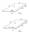
- said two additional plate members 19 and 20 are likewise provided with ready-made outer edges 28 and 29 to be fitted into the horizontal main frame members of the window main frame and both of them are angularly bent or curved along a bending line 30 and 31, resp., provided in parallel with and at a comparatively short distance from the outer edge and which separates a comparatively narrow outer part 32 and 33 abutting the window main frame and being almost perpendicular thereto and a comparatively wide inner part 34 and 35, resp., facing the actual attic and which in the assembled frame panel must be placed mainly vertically or mainly horizontally, as already mentioned.
- the bending angles u and v of plate members 19 and 20 illustrated in Figs 2 and 3 are different, viz. about 45° and about, 30°, so that said two members are used as top member 4 and bottom member 5, resp., dependent on the actual roof inclination.
- top member 4 and bottom member 5 of the frame panel as regards any roof inclination within the range determined by line marking sets 16 and 17 only present a deviation from the intended horizontal and vertical positioning that is quite indifferent to the appearance, viz. corresponding at a maximum to half the angular distance between the individual line markings, in the illustrated example ⁇ 2.5°.
- an auxiliary device may be used according to the invention which as illustrated in Fig. 5 may consist of a single disc member 36 having a rectilinear outer edge 37 to be held against a window 38 installed in the roof surface, the member 36 being held in a subsequently vertical plane.
- a plumb-line 39 is secured to disc member 36 in fixing point 38 at short distance from the outer edge 37 and below the fixing point 38 member 36 is provided with a fan-shaped set 40 of line markings 21c to 27c corresponding to the markings of sets 16 and 17 on the back of each plate member 10, i.e. at the same angular separation for instance of 5° and covering a range from 30° to 60° in relation to edge 37.
- disc member 36 is, moreover, provided with a bipartite marking 41 shaped as a circular arc to be used when selecting plate members 19 and 20 as the top member and bottom member, resp.
- line markings 21a to 23a of the upper line marking set 16 on plate members 10 are to be used solely in association with plate member 19 while line markings 24a to 27a are to be used solely in association with plate member 20.
- line markings 21b to 23b of the bottom line marking set 17 are to be used in association with plate member 20 and line markings 24b to 27b are to be used solely in association with plate member 19.
- predetermined line markings in either set are thus meant to be used for the first and the second of plate members 19 and 20, resp., considerably facilitates in practice the correct positioning of hole markings 18 which as mentioned must correspond exactly to the pre-drilled screw holes 41 at the end edge of plate members 19 and 20 and which, moreover, must be positioned so accurately that outer edges 28 and 29 of said plate members fit exactly in with grooves provided for that purpose in the horizontal main frame members independent of the application of members 19 and 20 as top member of bottom member.
- Figs 6 and 7 are sectional views of the frame panel when mounted.
- grooves 44 and 45, resp., are provided on the horizontal main frame members 42 and 43 of window 38, said grooves being adapted to receive outer parts 32 and 33 of plate members 19 and 20 serving as top member 4 and bottom member 5, resp., in such a manner that the angular position of outer parts 32 and 33 may vary in relation to a plane position perpendicular to the window main frame.
- grooves 28 and 49 provided in the side members of the main frame and are adapted to receive the ready-made outer edges 11 of plate members 10 used as side members 2 and 3.
- auxiliary device shaped as disc members 36 Following the determination of an actual roof inclination by means of the auxiliary device shaped as disc members 36, in the present case e.g. an inclination of about 40° corresponding to marking line 23c on disc member 36, cutting lines 50 and 51 are drawn parallel to marking lines 23a and 23b on plate member 10, but at a distance therefrom corresponding to the plate thickness.
- the distance T determining the width of the side member is then measured from the window main frame to sloping wall 6 at right angles to the plane of the window main frame, as illustrated in Fig. 6. Said measuring is effected preferably both at the uppermost horizontal main frame member 42 and opposite the corner between sloping wall 6 and vertical wall 7.
- the dimensions T are marked out on plate member 10 from its outer edge 11 and perpendicular thereto, following which the vertical cutting line 52 may be drawn between line markings 14 and 15.
- the height H is subsequently measured as the height distance from the projection of the lower edge of groove 44 in the upper horizontal main frame member 42 on to sloping wall 6 to the corner between sloping wall 65 and vertical wall 7 and said height dimension H is marked out on plate member 10 downwards from line marking 14 along cutting line 52 on to point 53.
- the desired depth B of the niche beneath the frame panel is then determined as the distance from the corner between sloping wall 6 and vertical wall 7 to the desired positioning of bottom member 8.
- the resulting dimension is then marked out on plate member 10 reckoned from point 53 along a cutting line 54 parallel to cutting line 51 that is parallel to line marking 23b, following which cutting line 55 is drawn at right angles to lines 51 and 54.
- the width of plate members 19 and 20 are adapted by cutting at a distance from inner edges 55 and 56, resp., located opposite outer edges 28 and 29, following which side members 2 and 3 may be screwed together with top member 4 and bottom member 5 - supplied in correct dimensions of length and, as mentioned, with pre-drilled screw holes as shown by 57 - into a substantially rectangular box that is subsequently positioned correctly in relation to the window main frame and sloping wall 6 and vertical wall 7 and secured thereto in a manner not shown.
- Bottom member 8 that may be prepared in situ or supplied as a separate part is finally mounted. In order to obtain access to the space behind vertical wall 7 bottom member 8 may be appropriately be hinged at the back.
- each of the fan-shaped line markings is solely constituted by perforation markings 18 provided along a line in the form of punched or blind holes.
Landscapes
- Engineering & Computer Science (AREA)
- Architecture (AREA)
- Electromagnetism (AREA)
- Civil Engineering (AREA)
- Structural Engineering (AREA)
- Physics & Mathematics (AREA)
- Securing Of Glass Panes Or The Like (AREA)
- Body Structure For Vehicles (AREA)
- Assembled Shelves (AREA)
- Door And Window Frames Mounted To Openings (AREA)
- Wing Frames And Configurations (AREA)
- Roof Covering Using Slabs Or Stiff Sheets (AREA)
- Arrangements Of Lighting Devices For Vehicle Interiors, Mounting And Supporting Thereof, Circuits Therefore (AREA)
Abstract
Description
- This invention relates to a frame panel kit for a window installed in an inclined roof, comprising plate members accommodating side plates for arrangement in vertical planes perpendicular to the roof surface and a top and a bottom member to be assembled with said plate members with their end edges abutting the opposing front surfaces thereof in such positions that in the installed position the top member and the bottom member are substantially horizontal and vertical, two fan-shaped sets of preferably angle-equidistant line markings being provided on the back of each of said plate members for use when arranging the top member and the bottom member, each line marking in the first set forming together with a line marking in the other set a pair of line markings perpendicular to each other.
- In order to avoid entirely manual handycraft production of frame panels in connection with the installation of windows in inclined roof surfaces a frame panel is known from EP-A-0141567 that may be supplied with side plates, top and bottom members in a building kit that can be easily assembled in situ and can be quickly mounted by allowing for adaptation to the actual roof thickness and inclination. It is prescribed for this known structure that adapting of the plate members of the kit in the transverse direction to an actual thickness of a sloping wall is to be performed by cutting-off from the outer edges of the plate members, which has the disadvantage of impeding a correct adaptation of the panel to the window main frame, e.g. by engagement with grooves therein. In order that said cutting-off may be effected, the end edges of the plate members constituted the side members are, on one hand, provided with a part close to the outer edge perpendicular to the window main frame and, on the other hand, with a bevelled part facing the inner edge and forming such an angle with the parallel outer and inner edges of the side member that the latter part of the end edge extends subsequently horizontally and substantially vertically at the upper and lower end of the side member, respectively. With a view to make a given side member applicable for more than one roof inclination it has further been suggested that the bevelled parts perpendicular to each other of the end edges of a side member form different angles, e.g. 40° and 50° or 30° and 60°, with the outer edge and inner edge of said side member. Said design does not, however, provide for covering a greater range of roof inclinations, e.g. from 30° to 60° with one and the same shape of the side members.
- The shape of the side members with end edges that are ready-made with bevelled parts extending at said angles entails, moreover, that undesired large deviations from the desired location of the top and bottom members in a horizontal and a vertical plane, resp., must be accepted for roof inclinations in the range between the angular magnitudes of the bevelled parts of the end edges.
- The latter disadvantages have been eliminated by a design of the type mentioned above known from DE-U-78 09 898 according to which a comparatively correct positioning of the top and the bottom members may be obtained by means of said line markings on the side members. In this known design the kit is supplied with side, top and bottom members in ready cut sizes also in the transverse direction and it is prescribed that an intermediary frame must be inserted between the frame panel assembly itself and the window frame, probably with the purpose of compensating for variations of the thickness of a sloping wall. In order to obtain an adaptation of the width of the horizontally placed top member in dependence on an actual roof inclination a bipartite design of the top member is further prescribed with a section of constant width positioned closest to the window main frame and an internal part of varying width dependent on the roof inclination and assembled therewith by means of a ribgroove connection so that said internal parts must be supplied in varying sizes to be adapted to different roof inclinations, and intermediary frames fitted to varying thicknesses of sloping walls must be supplied as well.
- It is the object of the invention to provide a frame panel kit of the type mentioned by which it is possible, as distinct from said prior designs, by one and the same kit, i.e. without changing the size and shape of the plate members forming part of the kit, to build up frame panels suited for any arbitrary roof inclination and any thickness of sloping walls within a considerable range, and a mainly horizontal top member and a mainly vertical bottom member are at the same time always obtained together with a good adaptation to the window main frame without making use of any intermediary frame.
- This is obtained according to the invention in that first and second additional plate members are used as top member and bottom member, each of said additional plate members being bent or curved into an angular shape along a bending line positioned at a short distance from the outer edge of the member and having angles of approximately 30° and 45°, resp., between the mainly plane parts of the plate members located on either side of the folding line, the plate members accommodating the side plates as well as said additional plate members having ready-made outer edges to be assembled with grooves in the installed window main frame and being width-adaptable to the thickness of the sloping wall by cutting from their internal edges, each set of said line marking on each of the plate members accommodating the side plates covering an angular range from 30° to 60° with the outer edge of the plate member, and predetermined line markings in either set being intended for the first and the second, resp., of said additional plate members.
- A building kit manufactured in this manner and comprising four plate members which for a given window are supplied with determined sizes and shapes provides for giving the frame panel a shape fitting in with an arbitrary roof inclination within a range, e.g., from approximately 27.5° to approximately 62.5° and with a maximum deviation from the ideal horizontal and vertical orientation of the top and bottom members of ± 2.5°. A suitable adaptation to an actual thickness of a sloping wall may at the same time be obtained and thus also a compensation for minor variations thereof, e.g. between the two vertical lateral surfaces of the light area. In view of the fact that the kit is supplied with ready-made outer edges of the plate member, e.g. fitting in with the grooves in the window main frame, a safe and tight connection with the window main frame is obtained as well.
- In respect of the fact that a determined roof inclination always requires one of the two additional plate members to be used as top member and the other as bottom member the entire above mentioned range can be covered without any need of interchanging the side members or turning them upside down as prescribed in the above mentioned European patent application. In a given kit the plate members accommodating the side plates will thus be predetermined for use in the left or right side of the light area and must always be mounted with the same orientation in the upward or downward direction.
- Thereby the particular advantage is obtained that the kit may be formed to fit in with a larger opening towards the room compared to the window light area proper, thereby providing for instance a niche within a vertical wall below the window.
- A preferred embodiment of the frame panel kit according to the invention suitable for that purpose is characterized in that the plate members accommodating the side plates are trapezoidal with parallel top and bottom edges perpendicular to said outer edge, the top edge having a length corresponding to a predetermined maximum thickness of a sloping wall and a minimum roof inclination, while the bottom edge has such an increased length in comparison with the top edge and the plate member has such a height that besides accommodating the side plate necessary for a light area positioned entirely in the inclined roof surfaces, said plate member also accommodates a plate part forming a side wall of a niche with a substantially horizontal bottom plate in vertical wall positioned below the window.
- The invention further relates to an auxiliary device to be used when assembling the frame panel from the kit. According to the invention and auxiliary device includes a disc-shaped member having a rectilinear edge to be held against the window while holding the member in a substantially vertical plane, a plumbline secured at a short distance from said edge, a set of fan-shaped line markings having a numbering corresponding to a numbering of either set of line markings on said plate members and in connection with the set of line markings a bipartite cicular marking for selection of said additional plate members as top member and bottom member, resp.
- By this very simple auxiliary device which without any noticeable price increase may be supplied to gether with the kit, user is capable of deciding in situ, by simply measuring without making use of any separate measuring instruments which line marking on the side plates in either set to use and which of the additional plate members to use as top member and bottom member, resp.
- The invention will now be explained in detail with reference to the schematical drawings, in which
- Fig. 1 is an example of a frame panel with an underlying window niche designed by means of the kit accordding to the invention,
- Figs 2, 3 and 4 illustrate embodiments of the plate members forming part of the kit.
- Fig. 5 illustrates an embodiment of an auxiliary device to be used when assembling the frame panel,
- Figs 6 and 7 illustrate a vertical and a horizontal sectional view, resp., of an installed frame panel, and
- Fig. 8 illustrates the plate member shown in Fig. 2 with marked cutting lines.
- In the example illustrated in Fig. 1 of the completed frame panel assembled from the kit according to the invention the frame panel consists of two
side members window 1 and a substantially horizontaltop member 4 and a substantiallyvertical bottom member 5. - At their internal edges facing the room the
side members internal sloping wall 6 and avertical cupboard wall 7 positioned therebeneath, in which the frame panel in the illustrated embodiment forms a window niche with a substantiallyhorizontal bottom plate 8 between thebottom member 5 and thevertical wall 7. The edges ofplate members -
Side members plate member 10 as illustrated in Fig. 2. Said member is produced, as will be described in the following, with a ready-madeouter edge 11 to be mounted on the window main frame, e.g. in engagement with a groove in the vertical main frame member. Thetop edge 12 and thebottom edge 13 are parallel and perpendicular to the outer edge, and the plate member intended for a determined window size has a height that is so much higher than the window height corresponding to the distance betweenline markings edges plate member 10 by installation at an arbitrary roof inclination will overlap the end edges of the top member and bottom member of the panel when said two members are positioned correctly in a horizontal and a vertical position, resp., i.e. at an angle withouter edge 11 equal to and complementary with respect to the roof inclination, respectively. - In the illustrated
example plate member 10 is trapezoidal with increasing width in the direction fromtop edge 12 towardsbottom edge 13 and the member has such a magnitude that its lower part beyond the line marking 15 may accommodate the part of the side member which in the embodiment in Fig. 1 delimits the niche located beneath the window. -
Plate member 10 illustrated in Fig. 2 and accommodatingside member 2 to be mounted on the left side of the lining is provided on the reverse side illustrated in the figure with two sets of fan-shaped line markings 16 and 17, resp.,outside line markings line markings 21a to 27a and 21b to 27b, resp., that are mainly angle-equidistant and which altogether covers an angular range from 30° to 60° in relation toouter edge 11, in the illustrated example corresponding to an angular separation of 5°. The line markings are made so that for a determined roof inclination one line marking is used from either set, e.g., 21a and 21b, for a roof inclination of 30°, said markings being at right angles to each other. - The line markings of
sets 16 and 17 may incidentally to be used to adaptplate member 10 by cutting to the orientation determined by the roof inclination of the top and bottom edges ofside member 2, but they are preferably provided with punchedmarkings 18, e.g. in the form of blind holes of comparatively low depth reckoned from the back of the member and placed along the line markings so as to correspond to pre-drilled screw holes at the end edges of the additional plate members that will be dealt with in the following and which accommodatetop member 5 andbottom member 5 of the frame panel. - As illustrated in Figs 3 and 4 said two
additional plate members outer edges bending line 30 and 31, resp., provided in parallel with and at a comparatively short distance from the outer edge and which separates a comparatively narrowouter part inner part - In accordance with the invention the bending angles u and v of
plate members top member 4 andbottom member 5, resp., dependent on the actual roof inclination. From the recognition that it is of minor importance as regards the appearance of the frame panel whetherouter parts plate members top member 4 andbottom member 5 of the frame panel as regards any roof inclination within the range determined byline marking sets 16 and 17 only present a deviation from the intended horizontal and vertical positioning that is quite indifferent to the appearance, viz. corresponding at a maximum to half the angular distance between the individual line markings, in the illustrated example ±2.5°. - In order to measure the roof inclination and thus select the actual line markings of
marking sets 16 and 17 and to determine the application ofplate members top member 4 andbottom member 5, resp., an auxiliary device may be used according to the invention which as illustrated in Fig. 5 may consist of asingle disc member 36 having a rectilinearouter edge 37 to be held against awindow 38 installed in the roof surface, themember 36 being held in a subsequently vertical plane. - A plumb-
line 39 is secured to discmember 36 infixing point 38 at short distance from theouter edge 37 and below thefixing point 38member 36 is provided with a fan-shaped set 40 ofline markings 21c to 27c corresponding to the markings ofsets 16 and 17 on the back of eachplate member 10, i.e. at the same angular separation for instance of 5° and covering a range from 30° to 60° in relation toedge 37. - In connection, with, for instance just opposite line marking set 40,
disc member 36 is, moreover, provided with a bipartite marking 41 shaped as a circular arc to be used when selectingplate members - For a given individual roof inclination defined as the angle of the roof surface with the horizontal plane in the range from 27.5° to 62.5°, the following Table will show the selection of line markings and the application of
plate members top member 4 and bottom member 5:
- It will appear from the Table that line markings 21a to 23a of the upper line marking set 16 on
plate members 10 are to be used solely in association withplate member 19 while line markings 24a to 27a are to be used solely in association withplate member 20. Inversely, line markings 21b to 23b of the bottom line marking set 17 are to be used in association withplate member 20 and line markings 24b to 27b are to be used solely in association withplate member 19. In the illustrated case with an odd number of line markings in either set it will be principally indifferent, as regards the middle angular sector of the range corresponding to line markings 24, whether use is made of one instruction or the other with respect to the application ofplate members plate members - The fact that predetermined line markings in either set are thus meant to be used for the first and the second of
plate members hole markings 18 which as mentioned must correspond exactly to thepre-drilled screw holes 41 at the end edge ofplate members outer edges members - Figs 6 and 7 are sectional views of the frame panel when mounted. As illustrated in Fig. 6,
grooves main frame members window 38, said grooves being adapted to receiveouter parts plate members top member 4 andbottom member 5, resp., in such a manner that the angular position ofouter parts - As illustrated in Fig. 7
grooves outer edges 11 ofplate members 10 used asside members - The cutting of
plate members 10 will be explained in the following with reference to Figs 6 and 8. - Following the determination of an actual roof inclination by means of the auxiliary device shaped as
disc members 36, in the present case e.g. an inclination of about 40° corresponding to markingline 23c ondisc member 36,cutting lines lines plate member 10, but at a distance therefrom corresponding to the plate thickness. - The distance T determining the width of the side member is then measured from the window main frame to sloping
wall 6 at right angles to the plane of the window main frame, as illustrated in Fig. 6. Said measuring is effected preferably both at the uppermost horizontalmain frame member 42 and opposite the corner between slopingwall 6 andvertical wall 7. The dimensions T are marked out onplate member 10 from itsouter edge 11 and perpendicular thereto, following which thevertical cutting line 52 may be drawn betweenline markings - The height H is subsequently measured as the height distance from the projection of the lower edge of
groove 44 in the upper horizontalmain frame member 42 on to slopingwall 6 to the corner between sloping wall 65 andvertical wall 7 and said height dimension H is marked out onplate member 10 downwards from line marking 14 alongcutting line 52 on topoint 53. - The desired depth B of the niche beneath the frame panel is then determined as the distance from the corner between
sloping wall 6 andvertical wall 7 to the desired positioning ofbottom member 8. The resulting dimension is then marked out onplate member 10 reckoned frompoint 53 along acutting line 54 parallel to cuttingline 51 that is parallel to line marking 23b, following which cuttingline 55 is drawn at right angles tolines - It is pointed out that the measuring and the marking-out steps have been explained here only very roughly. In practice it is generally necessary to make corrections of the thickness of plate and so on. However, such corrections may be pre-calculated and then specified in detailed directions for use supplied with the kit.
- After said two
side members markings 18 in actual line markings, the width ofplate members inner edges outer edges side members top member 4 and bottom member 5 - supplied in correct dimensions of length and, as mentioned, with pre-drilled screw holes as shown by 57 - into a substantially rectangular box that is subsequently positioned correctly in relation to the window main frame andsloping wall 6 andvertical wall 7 and secured thereto in a manner not shown.Bottom member 8 that may be prepared in situ or supplied as a separate part is finally mounted. In order to obtain access to the space behindvertical wall 7bottom member 8 may be appropriately be hinged at the back. - The manufacturing of
plate members 10 may be simplified in that each of the fan-shaped line markings is solely constituted byperforation markings 18 provided along a line in the form of punched or blind holes.
Claims (6)
Priority Applications (1)
| Application Number | Priority Date | Filing Date | Title |
|---|---|---|---|
| AT88303351T ATE77435T1 (en) | 1987-04-15 | 1988-04-14 | PANEL EQUIPMENT FOR WINDOW FRAMES AND AIDS FOR PREPARING WINDOW FRAMES. |
Applications Claiming Priority (2)
| Application Number | Priority Date | Filing Date | Title |
|---|---|---|---|
| DK1975/87 | 1987-04-15 | ||
| DK197587A DK157820C (en) | 1987-04-15 | 1987-04-15 | LIGHTING PANEL ASSEMBLY FOR A WINDOW IN A SHARED ROOF AREA, AND TOOL FOR USE IN MANUFACTURING A LIGHTING PANEL OUT OF THE ASSEMBLY. |
Publications (2)
| Publication Number | Publication Date |
|---|---|
| EP0287362A1 true EP0287362A1 (en) | 1988-10-19 |
| EP0287362B1 EP0287362B1 (en) | 1992-06-17 |
Family
ID=8109220
Family Applications (1)
| Application Number | Title | Priority Date | Filing Date |
|---|---|---|---|
| EP88303351A Expired - Lifetime EP0287362B1 (en) | 1987-04-15 | 1988-04-14 | Window frame panel kit and an auxiliary device for producing a window frame |
Country Status (4)
| Country | Link |
|---|---|
| EP (1) | EP0287362B1 (en) |
| AT (1) | ATE77435T1 (en) |
| DE (1) | DE3872030T2 (en) |
| DK (1) | DK157820C (en) |
Cited By (7)
| Publication number | Priority date | Publication date | Assignee | Title |
|---|---|---|---|---|
| DE4015240A1 (en) * | 1990-05-10 | 1991-11-21 | Rasmussen Kann Ind As | SIDE PANEL OF AN INNER LINING FOR ROOF WINDOWS AND KIT FOR PRODUCING SUCH AN INNER LINING |
| DE19514149A1 (en) * | 1995-04-15 | 1996-10-17 | Braas Gmbh | Connection lining for a window frame |
| DE19514150A1 (en) * | 1995-04-15 | 1996-10-17 | Braas Gmbh | Connection lining for a window frame |
| GB2337785A (en) * | 1998-05-27 | 1999-12-01 | Mila Hardware Ltd | A wing and frame with a visual alignment means |
| WO2001006080A1 (en) * | 1999-07-14 | 2001-01-25 | Multi-Tek A/S | Openable screen element such as a door |
| DE202013009449U1 (en) | 2013-10-10 | 2014-02-28 | Vkr Holding A/S | Measuring tool for preparing a window lining |
| EP3587695A1 (en) | 2018-06-28 | 2020-01-01 | VKR Holding A/S | Installation system comprising a plurality of bracket members and method for installation of a lining panel in a roof window |
Families Citing this family (1)
| Publication number | Priority date | Publication date | Assignee | Title |
|---|---|---|---|---|
| DK180686B1 (en) | 2019-09-13 | 2021-11-25 | Vkr Holding As | Window lining assembly with improved fittings and method for installing such a lining assembly on a window |
Citations (5)
| Publication number | Priority date | Publication date | Assignee | Title |
|---|---|---|---|---|
| US834765A (en) * | 1906-07-16 | 1906-10-30 | Jacob Sechler | Plumb-level. |
| US885076A (en) * | 1906-12-17 | 1908-04-21 | Axel Olson | Combination-tool. |
| US2724152A (en) * | 1952-11-19 | 1955-11-22 | Aurelio M Massano | Package dormer units |
| US3363369A (en) * | 1965-10-23 | 1968-01-16 | Earl E. Miller | All pitch chimney flashing |
| DK149655B (en) * | 1983-10-21 | 1986-08-25 | Rasmussen Holding As V Kann | ROOF WINDOW LIGHTING PANEL |
-
1987
- 1987-04-15 DK DK197587A patent/DK157820C/en not_active IP Right Cessation
-
1988
- 1988-04-14 DE DE8888303351T patent/DE3872030T2/en not_active Expired - Fee Related
- 1988-04-14 EP EP88303351A patent/EP0287362B1/en not_active Expired - Lifetime
- 1988-04-14 AT AT88303351T patent/ATE77435T1/en not_active IP Right Cessation
Patent Citations (5)
| Publication number | Priority date | Publication date | Assignee | Title |
|---|---|---|---|---|
| US834765A (en) * | 1906-07-16 | 1906-10-30 | Jacob Sechler | Plumb-level. |
| US885076A (en) * | 1906-12-17 | 1908-04-21 | Axel Olson | Combination-tool. |
| US2724152A (en) * | 1952-11-19 | 1955-11-22 | Aurelio M Massano | Package dormer units |
| US3363369A (en) * | 1965-10-23 | 1968-01-16 | Earl E. Miller | All pitch chimney flashing |
| DK149655B (en) * | 1983-10-21 | 1986-08-25 | Rasmussen Holding As V Kann | ROOF WINDOW LIGHTING PANEL |
Cited By (8)
| Publication number | Priority date | Publication date | Assignee | Title |
|---|---|---|---|---|
| DE4015240A1 (en) * | 1990-05-10 | 1991-11-21 | Rasmussen Kann Ind As | SIDE PANEL OF AN INNER LINING FOR ROOF WINDOWS AND KIT FOR PRODUCING SUCH AN INNER LINING |
| DE19514149A1 (en) * | 1995-04-15 | 1996-10-17 | Braas Gmbh | Connection lining for a window frame |
| DE19514150A1 (en) * | 1995-04-15 | 1996-10-17 | Braas Gmbh | Connection lining for a window frame |
| GB2337785A (en) * | 1998-05-27 | 1999-12-01 | Mila Hardware Ltd | A wing and frame with a visual alignment means |
| WO2001006080A1 (en) * | 1999-07-14 | 2001-01-25 | Multi-Tek A/S | Openable screen element such as a door |
| US7437853B1 (en) | 1999-07-14 | 2008-10-21 | Multi-Tek A/S | Openable screen element such as a door |
| DE202013009449U1 (en) | 2013-10-10 | 2014-02-28 | Vkr Holding A/S | Measuring tool for preparing a window lining |
| EP3587695A1 (en) | 2018-06-28 | 2020-01-01 | VKR Holding A/S | Installation system comprising a plurality of bracket members and method for installation of a lining panel in a roof window |
Also Published As
| Publication number | Publication date |
|---|---|
| DE3872030T2 (en) | 1993-01-14 |
| DE3872030D1 (en) | 1992-07-23 |
| DK157820C (en) | 1990-09-17 |
| ATE77435T1 (en) | 1992-07-15 |
| EP0287362B1 (en) | 1992-06-17 |
| DK197587A (en) | 1988-10-16 |
| DK157820B (en) | 1990-02-19 |
| DK197587D0 (en) | 1987-04-15 |
Similar Documents
| Publication | Publication Date | Title |
|---|---|---|
| US5375381A (en) | Building kit | |
| US4736559A (en) | Raised panel paneling system | |
| CA2251012C (en) | Height-adjusting element | |
| EP0287362A1 (en) | Window frame panel kit and an auxiliary device for producing a window frame | |
| US20100319278A1 (en) | Prefabricated staircase and finishing arrangement and installation method therefor | |
| US8919059B2 (en) | Crown moulding | |
| JP2010511812A (en) | Bracket for plug-in or fit-type joint between parts | |
| WO1995026450A1 (en) | Cladding board | |
| US3127703A (en) | Adjustable guide strips or ground members | |
| US9121185B2 (en) | Prefabricated staircase and finishing arrangement and installation method therefor | |
| US6607020B1 (en) | Screening arrangement and method for installation of such in a curb for a skylight | |
| US6647673B2 (en) | Standardized arched jamb assembly and method | |
| US5274902A (en) | Device and method for joining boards angularly edge-to-edge without mitering | |
| EP0141567B1 (en) | A window frame panel assembly for a roof window | |
| US4503897A (en) | Tool for use when fitting window frames, door frames and like structures | |
| JP3459405B2 (en) | Method of constructing around opening at the time of reforming and decorative member around opening to be used in the method | |
| US7146767B2 (en) | Standardized arched jamb assembly and method | |
| JP2961248B2 (en) | Interior wall equipment | |
| JPS5851340Y2 (en) | Window frame mounting device | |
| US1724333A (en) | Panel construction | |
| GB2401121A (en) | Stud wall perimeter channel | |
| JPH0481018B2 (en) | ||
| JPH0748818Y2 (en) | Fixed structure of ceiling base panel | |
| JPH05141023A (en) | Mounting structure for wall upper than picture rail | |
| JP3441830B2 (en) | Exterior wall opening structure |
Legal Events
| Date | Code | Title | Description |
|---|---|---|---|
| PUAI | Public reference made under article 153(3) epc to a published international application that has entered the european phase |
Free format text: ORIGINAL CODE: 0009012 |
|
| 17P | Request for examination filed |
Effective date: 19880806 |
|
| AK | Designated contracting states |
Kind code of ref document: A1 Designated state(s): AT BE CH DE ES FR GB IT LI NL SE |
|
| 17Q | First examination report despatched |
Effective date: 19900123 |
|
| GRAA | (expected) grant |
Free format text: ORIGINAL CODE: 0009210 |
|
| AK | Designated contracting states |
Kind code of ref document: B1 Designated state(s): AT BE CH DE ES FR GB IT LI NL SE |
|
| PG25 | Lapsed in a contracting state [announced via postgrant information from national office to epo] |
Ref country code: IT Free format text: LAPSE BECAUSE OF FAILURE TO SUBMIT A TRANSLATION OF THE DESCRIPTION OR TO PAY THE FEE WITHIN THE PRESCRIBED TIME-LIMIT;WARNING: LAPSES OF ITALIAN PATENTS WITH EFFECTIVE DATE BEFORE 2007 MAY HAVE OCCURRED AT ANY TIME BEFORE 2007. THE CORRECT EFFECTIVE DATE MAY BE DIFFERENT FROM THE ONE RECORDED. Effective date: 19920617 Ref country code: FR Effective date: 19920617 Ref country code: NL Effective date: 19920617 Ref country code: LI Effective date: 19920617 Ref country code: SE Effective date: 19920617 Ref country code: CH Effective date: 19920617 Ref country code: AT Effective date: 19920617 Ref country code: BE Effective date: 19920617 Ref country code: ES Free format text: THE PATENT HAS BEEN ANNULLED BY A DECISION OF A NATIONAL AUTHORITY Effective date: 19920617 |
|
| REF | Corresponds to: |
Ref document number: 77435 Country of ref document: AT Date of ref document: 19920715 Kind code of ref document: T |
|
| REF | Corresponds to: |
Ref document number: 3872030 Country of ref document: DE Date of ref document: 19920723 |
|
| REG | Reference to a national code |
Ref country code: CH Ref legal event code: PL |
|
| EN | Fr: translation not filed | ||
| NLV1 | Nl: lapsed or annulled due to failure to fulfill the requirements of art. 29p and 29m of the patents act | ||
| PG25 | Lapsed in a contracting state [announced via postgrant information from national office to epo] |
Ref country code: GB Effective date: 19930414 |
|
| PLBE | No opposition filed within time limit |
Free format text: ORIGINAL CODE: 0009261 |
|
| STAA | Information on the status of an ep patent application or granted ep patent |
Free format text: STATUS: NO OPPOSITION FILED WITHIN TIME LIMIT |
|
| 26N | No opposition filed | ||
| GBPC | Gb: european patent ceased through non-payment of renewal fee |
Effective date: 19930414 |
|
| PGFP | Annual fee paid to national office [announced via postgrant information from national office to epo] |
Ref country code: DE Payment date: 20060411 Year of fee payment: 19 |
|
| PG25 | Lapsed in a contracting state [announced via postgrant information from national office to epo] |
Ref country code: DE Free format text: LAPSE BECAUSE OF NON-PAYMENT OF DUE FEES Effective date: 20071101 |