EP0286092A1 - Apparatus for hanging and handling plate members - Google Patents
Apparatus for hanging and handling plate members Download PDFInfo
- Publication number
- EP0286092A1 EP0286092A1 EP88105555A EP88105555A EP0286092A1 EP 0286092 A1 EP0286092 A1 EP 0286092A1 EP 88105555 A EP88105555 A EP 88105555A EP 88105555 A EP88105555 A EP 88105555A EP 0286092 A1 EP0286092 A1 EP 0286092A1
- Authority
- EP
- European Patent Office
- Prior art keywords
- hanger
- electrode plates
- hangers
- clamp
- supporting frame
- Prior art date
- Legal status (The legal status is an assumption and is not a legal conclusion. Google has not performed a legal analysis and makes no representation as to the accuracy of the status listed.)
- Granted
Links
Images


Classifications
-
- C—CHEMISTRY; METALLURGY
- C25—ELECTROLYTIC OR ELECTROPHORETIC PROCESSES; APPARATUS THEREFOR
- C25C—PROCESSES FOR THE ELECTROLYTIC PRODUCTION, RECOVERY OR REFINING OF METALS; APPARATUS THEREFOR
- C25C7/00—Constructional parts, or assemblies thereof, of cells; Servicing or operating of cells
-
- C—CHEMISTRY; METALLURGY
- C25—ELECTROLYTIC OR ELECTROPHORETIC PROCESSES; APPARATUS THEREFOR
- C25C—PROCESSES FOR THE ELECTROLYTIC PRODUCTION, RECOVERY OR REFINING OF METALS; APPARATUS THEREFOR
- C25C7/00—Constructional parts, or assemblies thereof, of cells; Servicing or operating of cells
- C25C7/06—Operating or servicing
-
- C—CHEMISTRY; METALLURGY
- C25—ELECTROLYTIC OR ELECTROPHORETIC PROCESSES; APPARATUS THEREFOR
- C25D—PROCESSES FOR THE ELECTROLYTIC OR ELECTROPHORETIC PRODUCTION OF COATINGS; ELECTROFORMING; APPARATUS THEREFOR
- C25D17/00—Constructional parts, or assemblies thereof, of cells for electrolytic coating
- C25D17/16—Apparatus for electrolytic coating of small objects in bulk
- C25D17/28—Apparatus for electrolytic coating of small objects in bulk with means for moving the objects individually through the apparatus during treatment
Definitions
- This invention broadly relates to an apparatus for hanging and handling a plurality of plate members. More particularly, this invention relates to an apparatus suitable for lifting a plurality of electrode plates out of an electrolytic cell, transferring them to various working stations and then returning them to the electrolytic cell.
- Cranes and hoists are generally used for hanging and/or transferring various bodies in various fields. However, it is not convenient to use a conventional crane or hoist for lifting and transferring electrode plates in the electrowinning or electrolic refining of metals, since there are various problems as outlined below.
- anodes and cathodes are alternately arranged at predetermined intervals in an electrolytic cell. These electrodes are lifted and many of them are serviced, treated, changed or renewed before or after the operation.
- the cathodes are taken out of the electrolytic cell and transferred to the stripping operation for recovering electrodeposited zinc, and thereafter they are again returned to the cell.
- the anodes are serviced and repaired if necessary after every several runs.
- a crane or hoist has been used for lifting and transferring electrodes.
- hanging means are used for simultaneously lifting and facilitating servicing and changing of a plurality of electrodes, said means being provided with hooks which catch and pick up electrodes.
- the conventional hanging means are provided with hooks spaced at constant intervals, and the distance between the hooks cannot be varied. Therefore, the electrodes are carried in the closely spaced state to the stripping station. With such small a space between the electrode plates, the scraping operation is very troublesome. It would be very advantageous if the space between the electrode plates could be widened as desired.
- the conventional electrode-lifting means hang only electrodes of one kind, and are not provided with insulating means. Therefore, it is impossible to simultaneously lift electrodes of the different kinds by a conventional lifting means, because short-circuiting occurs.
- the present invention solves the above-described problems by providing a framework provided with a hanger structure which are provided with a plurality of hangers which can sling electrode plates and are movable.
- this invention provides an apparatus for hanging, transferring, separating apart, bringing together or releasing a plurality of plate members comprising a travelling framework with a driving means therefor; a hanger structure which is mounted on the framework, hangs a plurality of plate members, and is movable up-and-down; said hanger structure comprising a hanger-supporting frame, a plurality of hangers which are supported on the hanger-supporting frame and move along the hanger-supporting frame, driving means for moving the hangers, and hook means which are pivotably connected to each hanger and pick up the plate members.
- a plurality of hangers are movably mounted on rails laid on the hanger-supporting frame, the hangers are serially connected by means of link means so that the linked hangers can be expanded, contracted or moved as a whole by means of the hanger-driving means; and there are outside hangers and inside hangers, the outside hangers have legs on both ends, thus the outside hangers can encompass the inside hangers and thus the inside hangers can move through the space defined by the outside hangers.
- the apparatus of the present invention is provided with at least a pair of spaced and confronting clamp arms for clamping plate members.
- the clamp arms are pivotably connected to the underside of the hanger-supporting frame at their base ends and open and close in the direction of the thickness of the plate members and can bring together the plate members and tighten them when they are rotated by their driving means.
- the apparatus of the present invention is provided with a pair of confronting holder arms extending in the direction of the plane of the plate members and a driving means therefor.
- Each holder arm is pivotably secured to one of the hanger supporting frame beams at its base end. The other end thereof can detachably hold a clamp bar.
- the apparatus for handling plate members of the present invention comprises a framework which can travel and a hanger structure which can hang a plurality of plate members.
- the framework has the shape of a transversely long gate and having some depth in the travelling direction.
- the travelling of the framework can be effected by any means, manually for instance, although it is usually driven electrically.
- the framework can be suspended from the rails fixed to the ceiling of a plant building or can travel on rails laid on the floor of the plant. In the case where the apparatus handles electrode plates, the framework straddles an electrolytic cell.
- the framework includes a hanger structure therein.
- the hanger structure comprises a hanger-supporting frame which is supported by the framework so that the up-and down motion is possible.
- the hanger-supporting structure movably supports a plurality of hangers.
- the hanger-supporting structure is provided with a pair of guide rails on which the hangers are slidably mounted. Or otherwise, the hangers may be suspended from the rails.
- a plurality of hangers are serially linked by means of links, and means for moving the linked hangers toward one end or the other end of the hanger-supporting frames are provided.
- These means can be two chain mechanisms which separately move to draw the hangers along the rails or otherwise can be linear motors formed between the hangers and the hanger-supporting frames.
- Each hanger is provided with hook means which sling a plate member.
- the structure of the hook means is not specifically limited, but they are preferably a pair of hooks suspended from both ends of a hanger which catch protrusions of a plate member.
- two kinds overlappable alternately-placed of hangers are provided so that they can pick up plate members closely spaced from each other. That is to say, outside hangers and inside hangers are provided.
- the outside hanger has legs on both ends thereof and has a gate-like shape so that it can encompass an inside hanger between the two legs.
- the inside hangers can move through the space defined under the gate-like outside hangers.
- the apparatus of the present invention When the apparatus of the present invention is to be used for handling electrode plates for an electrolytic cell, it will be convenient if the outside hangers sling only the cathodes and the inside hangers sling only the anodes (or vice versa).
- the apparatus can be provided with clamp means for handling a plurality of plate members as a whole.
- Such clamp means comprises at least a pair of confronting clamp arms and curving means therefor.
- the base end of each clamp arm is pivotably secured to the underside of the beam of the hanger-supporting frame, on which the guide rails are laid, and inside of the hooks extending downward from the hanger, and the other end thereof extends downward and is swingable in the direction of the thickness of the plate members. That is, the pair of clamp arms are provided at positions where they do not interfere with the movement of the hangers.
- This clamp means can be driven by any means including hydraulic cylinder, although electrically-operated cylinder mechanism is preferred.
- the clamp arms stand by under the hanger-supporting frame therealong at the time when the hangers move and start the clamping motion driven by the driving means when the plate members are brought together by the operation of the hangers.
- the apparatus is further provided with a mechanism which bundles a plurality of plate members brought together by means of clamp bars.
- This mechanism comprises at least a pair of confronting holder arms which are provided in the direction perpendicular to the direction of the clamp arms, that is, in the direction of the plane of the plate members in the vicinity of the clamp arms.
- the base end of each thereof is pivotably secured to the hanger-supporting frame outside of the movement range of the hangers.
- the distal end detachably holds a clamp bar.
- the pair of the holder arms stand by opened sideward under the hanger-supporting frame.
- the holder arms move toward the bundle of plate members driven by said driving means, and cause the clamp bar to press the edges of the plate members.
- the edges of the plurality of plate members are flushed and the plate members are bundled together.
- the holder arms release the clamp bars, which retract upward to the stand-by positions.
- the apparatus for handling plate members provided with the hanger structure and a clamp structure in accordance with the present invention can suitably be used for handling electrode plates in electrolytic cells as explained below.
- the framework travels astride an electrolytic cell or cells and temporarily halts at one predetermined electrolytic cell.
- the anode plates and the cathode plates are alternately arranged with a narrow space maintained therebetween by means of a spacer or a frame supported by clamp bars and are immersed in the electrolytic cell.
- one end of the cross bar of each anode plate and cathode plate is in contact with a respective bus bar and the other end is insulated.
- the hanger structure is designed so that the space between the hook of an outside hanger and the hook of an adjacent inside hanger is the same and equal to the space between an anode plate and a cathode plate when the linked hangers are in the most contracted state.
- the hanger-supporting frame is lowered and the hooks of the hangers catch the ears (protrusions) of the electrode plates, and the hanger structure is lifted together with the electrodes.
- the holder arms move downward to hold the clamp bars and detach them from the bundle of the electrode plates and return to the stand-by position.
- the electrode plates Before, during or after the travelling of the framework, the electrode plates are widely spaced apart by the movement of the hangers. Under this condition, the electrode plates are subjected to various treatments, stripping, servicing, repair, etc. Thereafter, the hangers are down together to the approximately central position. After the clamp arms and the holder arms operate to bring the electrode plates tightly together and the electrode plates are bundled integrally by the clamp bars, the hanger-supporting frame is lowered to immerse the set of the electrodes in the electrolytic cell. The hanger-supporting frame is then lifted and the linked hangers are moved to the other part of the same electrolytic cell or another electrolytic cell by themselves or together with the framework if required.
- the apparatus of the present invention can lift a plurality of plate members closely arranged side by side, space them apart as desired, and bring them together again. Handling of the electrode plates is easy and the apparatus enables a set of arranged electrode plates to be applied to a separate electrolytic cell. Also inter-electrodes intervals can be selected as desired.
- the apparatus of the present invention can accurately pick up closely spaced electrode plates, and immerse the electrodes at an accurate position in the electrolytic cell. Therefore, it makes it possible to arrange the elelctrode plates very closely to achieve high efficiency electrolysis.
- the apparatus of the present invention can lift the anode plates and cathode plates simultaneously without cutting of electric current. Therefore both cathodes and anodes can be simultaneously treated or serviced. That is, the treatments of the cathodes and the anodes can be simultaneously effected during one to-and-fro movement of the apparatus, since the distance between a cathode and an anode can be widely spaced. Thus the operation time can greatly be shortened.
- the apparatus of the present invention enables automation of the whole electrowinning process, since sequential operation of conveyance of electrode plates for immersion, lifting and lowering of electrodes, stripping of deposited metal, polishing and surface-treatment, etc. of electrodes is made possible by this apparatus.
- Appendix is not limited to handling of electrode plates in the electrowinning of metals but the apparatus is generally applicable to cases where a plurality of closely arranged plate members are simultaneously lifted, spaced apart for any treatment or transferred to another position.
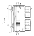
- An apparatus for handling electrode plates comprises a framework 10 which travels astride a rectangular electrolytic cell or cells 1, 1' driven by a driving mechanism 20 which is secured to the framework at a beam (not shown) (Figs. 1 & 2).
- the framework is a gate-like structure 11a, 11b which is transversely long and has some depth in the travelling direction.
- Two pairs of suspending means 12a, 12b are secured to beams (not shown).
- the framework is movably suspended from a pair of rails 13a, 13b fixed to the ceiling of the plant building by means of the suspending means.
- the suspending means 12a, 12b are provided with supporting rollers 14a, 14b which rotate in contact with the rails.
- the framework can travel over the electrolytic cell along the rails 13a, 13b.
- the framework can be designed so that the transverse length thereof is far longer than the length of the electrolytic cell and can straddle two or more electrolytic cells.
- Each rail 13a, 13b is provided with a rack 21 on the underside surface thereof.
- Pinions 22 which engage with the racks or the rails are secured to a rotating shaft 23 which is driven by a driving means secured on a beam (not shown) (Figs. 1 and 3).
- the shaft 23 is rotated by a motor 18a which is secured to the beam (not shown) by means of fixing means 24.
- the rack and pinion can alternatively be provided on the side surface of the rails.
- the suspending means and the driving means are separately provided, which is helpful for preventing slipping and/or rolling motion during travelling and thus enables the framework to stop at a very precise position. That is, the rack and pinion mechanism does not allow slipping and the supporting rollers 14a, 14b serve to prevent rolling motion.
- a linear motor can be employed as a driving and travelling means as explained in detail later.
- the framework can be designed so that it travels on the rails laid on the floor instead of being suspended from the overhead rails.
- sensors are provided at suitable positions and rotation of the driving motor is controlled and a dynamic brake is actuated by the signals generated by the sensors.
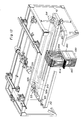
- the hanger structure 40 comprises a hanger-supporting frame 30 which bears a plurality of hangers 41 an 42 (Figs. 1 and 4).
- the hanger-supporting frame 30 is a rectangular frame comprising two pairs of parallel beam members 30a, 30a, which is supported by a pair of screw shafts 15a, 15b secured to the side frames of the framework 10. That is, the hanger-supporting frame 30 extends transversely and is provided with a nut means 31a, 31b at the center of each side beam. The nut means engage with the screw shafts 15a, 15b and thus the hanger-supporting frame can be lifted or lowered by the rotation of the shafts 15a, 15b.
- the upper ends of the screw shafts are connected to a driving shaft 17 secured to a beam (not shown) via bevel gear means 16.
- the driving shaft 17 is rotated by a driving motor 18b.
- guide protrusions 33a, 33b (Fig. 4) are provided so as to contact the corner pillars of the framework 10.
- the hanger-supporting frame 30 is lifted or lowered driven by the screw shaft and guided by the corner pillars.
- the two shafts 15a, 15b are synchronously rotated.
- the lift mechanism is conveniently provided with a mechanism which stops the hanger-supporting frame at several predetermined levels. Such a mechanism has sensors provided at the halting positions, which generate signals to be transmitted to the driving motor 18b to stop it.
- the hanger-supporting frame 30 is provided with guide rails 34a, 34b in the transverse direction (Figs. 5A & 6).
- Hangers 41, 42 for hanging electrode plates are slidably mounted on the guide rails 34a, 34b. The hangers move along the guide rails 34a, 34b and they can be spaced apart in the transverse direction or brought together.
- outside hangers 41 and inside hangers 42 there are outside hangers 41 and inside hangers 42.
- the outside hangers 41 have legs 41a, 41b at both ends. The legs form sliding shoes. Both ends of the inside hangers 42 form sliding shoes per se.
- the guide rail 34a, 34b are provided parallel on the beams 30c respectively corresponding to the outside hangers and the inside hangers. Insulating members 35 are sandwitched between the guide rails 34a, 34b and the hanger-supporting beams 30c, and, therefore, the anodes and the cathodes can be lifted simultaneously without short circuiting.
- Each hanger 41, 42 is provided with hook means 61a, 61b; 62a, 62b as shown in Figs. 5A, 5B and 6.
- the hook means is a U-shape suspending member and each hanger has a pair of hooks. The lower end of the hook member extends so that it can catch the ear 80 of a cross bar of an electrode plate.
- the hook members are provided with a tilting mechanism 70 as shown in Fig. 5B.
- the tilting mechanism 70 comprises, for instance, a rotatable polygonal rod 63a, 63b; 64a, 64b which extends to penetrate through the end portion of the hangers 41, 42 and a hole means slidably engageable with said polygonal rod provided at the upper portion of the hook member.
- the example shown in Figs. 5A and 5B is a pentagonal rod and a pentagonal hole.
- a pair of rotatable rods are provided on each hanger and the pair of rods synchronously rotate in opposite directions. Therefore, a pair of hook members are tilted oppositely, that is, the lower ends of the pair of hook members open or close.
- the rods are insulated.
- the rotatable rods are rotated by a cylinder mechanism 65 provided at the ends of the hanger-supporting meams via bevel gears as shown in Fig. 7.
- the rotatable rods 63a etc. are not necessarily polygonal but it may be elliptic. Or otherwise, the rod is cylindrical with a groove which receives a key means provided in the hook member. Any mechanism which can cause rotation will do.
- the tilting mechanism can be a small actuator provided on each hanger.
- the above-described rotatable rod is simple and convenient.
- a mechanism which controls the tilting of the hook members is provided. This can also comprise sensors as described above.
- the above-described hanger system is provided with driving mechanism 50 for moving hangers.
- An example thereof is chain mechanisms as shown in Figs. 6 and 7.
- two pairs of endless chains 51a, 51b, 52a, 52b are set up in the transverse direction between sprocket wheels (Fig. 6), which are driven by driving means 53 and 54.
- One pair of chains move in the opposite directions from the other.
- the outside hangers 41a, 41b, 41c ... are linked with connecting links 43a, 43b, 43c ... (Fig. 7).
- the inside hangers 42a, 42b, 42c, 42d, 42e, 42f, 42g ... are also linked together with connecting links 44a, 44b.
- the end one of the outside hangers is a tractive hanger 45, which simultaneously works as an inside hanger. That is, the end outside hanger 45 is provided with the same hook members as those of the inside hanger and is linked with an adjacent inside hanger by means of a link and is also linked with the adjacent outside hanger 41 by means of a connecting arm 46 having a slot. The length of the slot is the same as the length of a link piece. The slot engages with a protrusion 47.
- the linked hangers 41, 42 are spaced apart until the adjacent hangers are moved apart by the length of a pair link pieces.
- the linked hangers 41, 42 are brought together.
- the distance between an outside hanger and the adjacent inside hanger is designed so that it is equal to the space between an anode plate and the adjacent cathode, which are driven by driving mechanisms 53, 54.
- the hangers brought together can be moved in one direction en bloc.
- the framework 10 stands still at the predetermined electrolytic cell.
- the hanger-supporting frame 30 in which the hangers have been brought together at the predetermined position is lowered so that the hooks thereof reach the ears of the electrode plates.
- the rotation rods 63a, 64b rotate to tilt the hooks of the hangers to catch the ears of the electrode plates.
- the hanger-supporting frame 30 is lifted and is moved to an electrode-treatment station together with the framework 10.
- the chain mechanisms 51 and 52 drive the plurality of the hangers 41, 42 so as to space them apart.
- the framework 10 will be moved to the other of the same electrolytic cell or another electrolytic cell, during which the chains 51, 52 drive the hangers 41, 42 to bring them together.
- the hanger- supporting frame is lowered so as to place the electrode plates in the cell and release them.
- the hanger-supporting frame is again lifted and moved to another electrolytic cell if required.
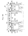
- Figs. 10 - 18 show an apparatus for handling electrolytic cells provided with electrode-clamping devices.
- the framework 10, the driving means 20 therefor, the hanger structure 40, the driving mechanism 50 for the hangers 41, 42, the hook mechanism 60, etc. are entirely the same as described above.
- two pairs of clamp arms 110, 111 and a pair of holder arms 120 are provided on the underside of the hanger-supporting frame 30 at the approximate center of the frames.
- a pair of clamp arms 110 and 111 are secured to the underside surface of a frame of the hanger-supporting frame as shown in Fig. 13.
- the base ends 110 a and 111a of the clamp arms 110, 111 are pivotably secured to the frame, and each rotating shaft thereof is connected to a cylinder mechanism 130 secured to the frame 30 via a connecting rod 110c or 111c.
- the other ends 110 b and 111b of the clamp arms 110, 111 are extended downward and bent toward the electrode plates 100.
- These pairs of the clamp arms are located at the same position in each beam and are arranged symmetrically, and they are positioned between the hooks 61a or 61b of the outside hangers and the hooks 62a or 62b of the inside hangers so as not to hinder the movement of the hangers 41, 42 (Fig. 5).
- the above-described two pairs of the clamp arms 110, 111 are lifted to the underside of the beam 30 in the stand-by condition while the hangers 41, 42 move carrying the electrode plates 100 as shown in Fig. 10.
- the clamp arms 110, 111 are lowered toward the electrode plates by means of the cylinder mechanism 130 as shown in Figs. 10 and 11.
- the clamp arms clamp the electrode plates and tighten them.
- the anode plates and cathode plates are insulated and fixed by means of a frame.
- a pair of holder arms 120, 121 are provided on the hanger-supporting frame 30 as shown in Fig. 14.
- the base end 120a, 121 a of each holder arm 120a, 121 a is pivotably secured to each opposite side beam of the hanger-supporting frame 30 and the holder arms 120, 121 are driven by cylinder mechanism 140 secured on the underside of the beam 30 via pins 120c, 121c.
- the other end (120b, 121) of the holder arms 120, 121 extend to the side of the electrode plates 100 and are provided with a clamp bar holder 150 respectively.
- the ends of the holder arms 120, 121 face the side edges of the electrode plates when they are lowered utmost.
- the clamp bar holder 150 is a clip means as shown in Fig. 15 comprising a pair of pivoted level members 150a, a supporting shaft 150e, a resilient means 150b which tends to open the distal ends of the lever members 150a, a pushing member 150c which closes the distal ends of the lever members 150a overcoming the resistance to the resilient means 150b and a driving motor 150f which drives the pushing member 150c via gear mechanism 150d.
- the lever members 150a detachably holds a clamp bar 160.
- the clamp bar is a rod-like member which extends to a length corresponding to the total thickness of the bundled electrode plates and has a claw 160a at each end to hold the bundle of the electrodes as shown in Fig. 16.
- the pair of the holder arms 120, 121 are also located outside of the travelling course of the hangers 41, 42.
- the holder arms 120, 121 respectively holding a clamp bar are held opened sideway in the stand-by condition while the hangers 41, 42 move carrying the electrode plates as shown in Fig. 10.
- the hangers are moved to the center of the hanger-supporting frame 30 bringing the electrode plates together and the clamp holders 110, 111 tighten the electrodes plates as shown in Fig. 11, the holder arms 120, 121 are lowered toward the bundle of the electrode plates as shown in Fig. 14. and the clamp bars 160 flush the edges of bundled electrode plates 100 and clamp the electrode plates.
- the holder arms 120, 121 release the clamp bars and are returned to the initial stand-by position.
- the bundled and clamped electrode plates are hung by the hangers and transferred to any desired station.
- the disengagement of the clamp bars is effected by the reversing the aforesaid procedures.
- the holder arms are lowered from the stand-by positions and clasp the clamp bars 160, detach them from the electrode plates and are lifted again to the stand-by positions.
- the electrode plates are made free by the detachment of the clamp bars.
- Fig. 17 shows another embodiment of the holder arm.
- the structures of the base end 120a. 121a, the distal ends 120b, 121b and the holder 150 per se are the same as in the embodiment represented by Fig. 13.
- This embodiment is characterized by being provided with an electrode-plate flushing mechanism 170.
- the plate-edge flushing mechanism 170 comprises a pusher 180 which touches the edges of the cross bars of the electrodes, a supporting member 181 which resiliently holds said pusher 180 and a frame 182 supporting the supporting member 181, which frame is secured to the holder arm 120, 121.
- the holder arms with the flushing mechanisim 170 are lowered so that the pusher 180 touch the head bars and the positioning bars press the cross bars 100a of the electrodes from both sides so as to flush the edges thereof.
- the holder arms 120, 121 are moved toward the electrode plates 100, and thus the clamp bars 160 are fixed.
- the pushers 180 retract from the cross bars 100a.
- the clamp bars are disengaged, the pushers are held at the retracted positions beforehand.
- the aforesaid clamp arms operate so as to tighten the bundled electrodes.
- the holder arms 120, 121 are lowered and hold the clamp bars and detach them from the edges of the bundled electrode plates and are returned to the stand-by position with them.
- the clamp arms are also returned to the stand-by position.
- the apparatus of the present invention is used, for example, for handling the electrodes for an electrolytic cell as follows.
- the apparatus is first moved to an electrolytic cell by means of the driving means 20 and the travelling mechanism and stands still there.
- the hanger structure 30 is lowered so that the hooks 61a - 62b reach the ears of the cross bars of the electrode plates 100.
- the hooks are tilted so as to catch the ears 100b by means of the rotatable rods 63a, 63b.
- the hanger-supporting frame 30 is lifted hanging a plurality of electrode plates from the electrolytic cell.
- the holder arms 120, 121 are lowered and hold the clamp bars 160 which have clamped the electrode plates and disengage them from the electrode plates.
- the framework 10 moves to an electrode treating station, during which the hangers 41, 42 are spaced apart by means of the chain mechanism 51, 52.
- the hanger structure 40 carries the electrode plates 100 to stations for servicing, cleaning, etc. of the anodes, stripping, polishing, etc. of the cathodes, etc. as required.
- the hangers are again brought together to the central portion by the chain means 51, 52.
- the clamp arms 110, 111 are lowered to tighten the electrode plates and further the holder arms 120, 121 are lowered to attach the clamp bars 160 to the bundled electrode plates.
- the holder arms then release the clamp bars.
- the clamp arms 110, 111 and the holder arms 120, 121 are lifted to the stand-by positions, and the hangers also release the electrode plates and the hanger structure is lifted leaving the electrodes in the electrolytic cell. This operation is repeated as required.
Abstract
Description
- This invention broadly relates to an apparatus for hanging and handling a plurality of plate members. More particularly, this invention relates to an apparatus suitable for lifting a plurality of electrode plates out of an electrolytic cell, transferring them to various working stations and then returning them to the electrolytic cell.
- Cranes and hoists are generally used for hanging and/or transferring various bodies in various fields. However, it is not convenient to use a conventional crane or hoist for lifting and transferring electrode plates in the electrowinning or electrolic refining of metals, since there are various problems as outlined below.
- Hereinafter in this specification, the term "electrowinning" is used as including "electrolytic refining".
- In the electrowinning of metals, a plurality of anodes and cathodes are alternately arranged at predetermined intervals in an electrolytic cell. These electrodes are lifted and many of them are serviced, treated, changed or renewed before or after the operation. In the electrowinning of zinc, for instance, the cathodes are taken out of the electrolytic cell and transferred to the stripping operation for recovering electrodeposited zinc, and thereafter they are again returned to the cell. The anodes are serviced and repaired if necessary after every several runs.
- As mentioned above, a crane or hoist has been used for lifting and transferring electrodes. And hanging means are used for simultaneously lifting and facilitating servicing and changing of a plurality of electrodes, said means being provided with hooks which catch and pick up electrodes. The conventional hanging means are provided with hooks spaced at constant intervals, and the distance between the hooks cannot be varied. Therefore, the electrodes are carried in the closely spaced state to the stripping station. With such small a space between the electrode plates, the scraping operation is very troublesome. It would be very advantageous if the space between the electrode plates could be widened as desired. The conventional electrode-lifting means hang only electrodes of one kind, and are not provided with insulating means. Therefore, it is impossible to simultaneously lift electrodes of the different kinds by a conventional lifting means, because short-circuiting occurs.
- The present invention solves the above-described problems by providing a framework provided with a hanger structure which are provided with a plurality of hangers which can sling electrode plates and are movable.
- Broadly, this invention provides an apparatus for hanging, transferring, separating apart, bringing together or releasing a plurality of plate members comprising a travelling framework with a driving means therefor; a hanger structure which is mounted on the framework, hangs a plurality of plate members, and is movable up-and-down; said hanger structure comprising a hanger-supporting frame, a plurality of hangers which are supported on the hanger-supporting frame and move along the hanger-supporting frame, driving means for moving the hangers, and hook means which are pivotably connected to each hanger and pick up the plate members.
- In a preferred embodiment of the present invention, a plurality of hangers are movably mounted on rails laid on the hanger-supporting frame, the hangers are serially connected by means of link means so that the linked hangers can be expanded, contracted or moved as a whole by means of the hanger-driving means; and there are outside hangers and inside hangers, the outside hangers have legs on both ends, thus the outside hangers can encompass the inside hangers and thus the inside hangers can move through the space defined by the outside hangers.
- In a preferred embodiment, the apparatus of the present invention is provided with at least a pair of spaced and confronting clamp arms for clamping plate members. The clamp arms are pivotably connected to the underside of the hanger-supporting frame at their base ends and open and close in the direction of the thickness of the plate members and can bring together the plate members and tighten them when they are rotated by their driving means.
- In a preferred embodiment, the apparatus of the present invention is provided with a pair of confronting holder arms extending in the direction of the plane of the plate members and a driving means therefor. Each holder arm is pivotably secured to one of the hanger supporting frame beams at its base end. The other end thereof can detachably hold a clamp bar. When the holder arms are rotated by the driving means toward the plate members, which have been brought together by the clamp arms, the holder arms can cause the clamp bars to hold the edges of the bundle of the plate members.
- Hereinafter, we simply call the apparatus of this invention an apparatus for handling plate members.
- The apparatus for handling plate members of the present invention comprises a framework which can travel and a hanger structure which can hang a plurality of plate members.
- The framework has the shape of a transversely long gate and having some depth in the travelling direction. The travelling of the framework can be effected by any means, manually for instance, although it is usually driven electrically. The framework can be suspended from the rails fixed to the ceiling of a plant building or can travel on rails laid on the floor of the plant. In the case where the apparatus handles electrode plates, the framework straddles an electrolytic cell.
- The framework includes a hanger structure therein. The hanger structure comprises a hanger-supporting frame which is supported by the framework so that the up-and down motion is possible. The hanger-supporting structure movably supports a plurality of hangers. For instance, the hanger-supporting structure is provided with a pair of guide rails on which the hangers are slidably mounted. Or otherwise, the hangers may be suspended from the rails. A plurality of hangers are serially linked by means of links, and means for moving the linked hangers toward one end or the other end of the hanger-supporting frames are provided. Thus the linked hangers can be moved together as a whole, expanded or contracted. These means can be two chain mechanisms which separately move to draw the hangers along the rails or otherwise can be linear motors formed between the hangers and the hanger-supporting frames.
- Each hanger is provided with hook means which sling a plate member. The structure of the hook means is not specifically limited, but they are preferably a pair of hooks suspended from both ends of a hanger which catch protrusions of a plate member.
- Preferably, two kinds overlappable alternately-placed of hangers are provided so that they can pick up plate members closely spaced from each other. That is to say, outside hangers and inside hangers are provided. The outside hanger has legs on both ends thereof and has a gate-like shape so that it can encompass an inside hanger between the two legs. Thus the inside hangers can move through the space defined under the gate-like outside hangers.
- When the apparatus of the present invention is to be used for handling electrode plates for an electrolytic cell, it will be convenient if the outside hangers sling only the cathodes and the inside hangers sling only the anodes (or vice versa).
- In a preferred embodiment of the present invention, the apparatus can be provided with clamp means for handling a plurality of plate members as a whole.
- Such clamp means comprises at least a pair of confronting clamp arms and curving means therefor. The base end of each clamp arm is pivotably secured to the underside of the beam of the hanger-supporting frame, on which the guide rails are laid, and inside of the hooks extending downward from the hanger, and the other end thereof extends downward and is swingable in the direction of the thickness of the plate members. That is, the pair of clamp arms are provided at positions where they do not interfere with the movement of the hangers. Thus the clamps can bring the hanging plate members together and tighten them when rotated by the above-mentioned driving means. This clamp means can be driven by any means including hydraulic cylinder, although electrically-operated cylinder mechanism is preferred.
- The clamp arms stand by under the hanger-supporting frame therealong at the time when the hangers move and start the clamping motion driven by the driving means when the plate members are brought together by the operation of the hangers.
- In a preferred embodiment of the present invention, the apparatus is further provided with a mechanism which bundles a plurality of plate members brought together by means of clamp bars. This mechanism comprises at least a pair of confronting holder arms which are provided in the direction perpendicular to the direction of the clamp arms, that is, in the direction of the plane of the plate members in the vicinity of the clamp arms. The base end of each thereof is pivotably secured to the hanger-supporting frame outside of the movement range of the hangers. The distal end detachably holds a clamp bar. The pair of the holder arms stand by opened sideward under the hanger-supporting frame. After a plurality of plate members are brought together by the clamp arms, the holder arms move toward the bundle of plate members driven by said driving means, and cause the clamp bar to press the edges of the plate members. Thus the edges of the plurality of plate members are flushed and the plate members are bundled together. Then the holder arms release the clamp bars, which retract upward to the stand-by positions.
- The apparatus for handling plate members provided with the hanger structure and a clamp structure in accordance with the present invention can suitably be used for handling electrode plates in electrolytic cells as explained below.
- The framework travels astride an electrolytic cell or cells and temporarily halts at one predetermined electrolytic cell. At this time, the anode plates and the cathode plates are alternately arranged with a narrow space maintained therebetween by means of a spacer or a frame supported by clamp bars and are immersed in the electrolytic cell. Of course, one end of the cross bar of each anode plate and cathode plate is in contact with a respective bus bar and the other end is insulated. The hanger structure is designed so that the space between the hook of an outside hanger and the hook of an adjacent inside hanger is the same and equal to the space between an anode plate and a cathode plate when the linked hangers are in the most contracted state. Then the hanger-supporting frame is lowered and the hooks of the hangers catch the ears (protrusions) of the electrode plates, and the hanger structure is lifted together with the electrodes. The holder arms move downward to hold the clamp bars and detach them from the bundle of the electrode plates and return to the stand-by position.
- Before, during or after the travelling of the framework, the electrode plates are widely spaced apart by the movement of the hangers. Under this condition, the electrode plates are subjected to various treatments, stripping, servicing, repair, etc. Thereafter, the hangers are down together to the approximately central position. After the clamp arms and the holder arms operate to bring the electrode plates tightly together and the electrode plates are bundled integrally by the clamp bars, the hanger-supporting frame is lowered to immerse the set of the electrodes in the electrolytic cell. The hanger-supporting frame is then lifted and the linked hangers are moved to the other part of the same electrolytic cell or another electrolytic cell by themselves or together with the framework if required.
- The apparatus of the present invention can lift a plurality of plate members closely arranged side by side, space them apart as desired, and bring them together again. Handling of the electrode plates is easy and the apparatus enables a set of arranged electrode plates to be applied to a separate electrolytic cell. Also inter-electrodes intervals can be selected as desired.
- The apparatus of the present invention can accurately pick up closely spaced electrode plates, and immerse the electrodes at an accurate position in the electrolytic cell. Therefore, it makes it possible to arrange the elelctrode plates very closely to achieve high efficiency electrolysis.
- The apparatus of the present invention can lift the anode plates and cathode plates simultaneously without cutting of electric current. Therefore both cathodes and anodes can be simultaneously treated or serviced. That is, the treatments of the cathodes and the anodes can be simultaneously effected during one to-and-fro movement of the apparatus, since the distance between a cathode and an anode can be widely spaced. Thus the operation time can greatly be shortened.
- The apparatus of the present invention enables automation of the whole electrowinning process, since sequential operation of conveyance of electrode plates for immersion, lifting and lowering of electrodes, stripping of deposited metal, polishing and surface-treatment, etc. of electrodes is made possible by this apparatus.
- Application of the apparatus of the present invention is not limited to handling of electrode plates in the electrowinning of metals but the apparatus is generally applicable to cases where a plurality of closely arranged plate members are simultaneously lifted, spaced apart for any treatment or transferred to another position.
-
- Fig. 1 is an overall perspective view of the apparatus of an embodiment of the present invention wherein some details are omitted.
- Fig. 2 is an elevational view of the apparatus of Fig. 1. wherein only pertinent members are shown.
- Fig. 3 is a partial elevational view showing the suspension means and a part of driving means for travelling of the apparatus.
- Fig. 4 is a plain view of the hanger structure of the apparatus of Fig. 1.
- Fig. 5A is a partly cross-sectional side elevational view showing the hangers.
- Fig. 5B is a partial perspective view of hook means of the hangers.
- Fig. 6 is a partial perspective view showing the hanger structure.
- Fig. 7 is a partial perspective view showing the arrangement of the hangers.
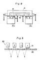
- Figs. 8 and 9 are schematic presentations showing hanger-carrying means using linear motors.
- Figs. 10 to 12 are partial perspective views of the apparatus of Fig. 1 in which clamp means are provided.
- Fig. 13 is a partial elevational view showing the first clamp means (clamp arms).
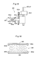
- Fig. 14 is a partial side elevational view showing the second clamp means (holder arms).
- Fig. 15 is an enlarged partial side view showing clamp bar holder.
- Fig. 16 is a partial plan view showing clamp bars.
- Fig. 17 is a partial elevational view showing movement of the second clamp means.
- Fig. 18 is a partial plain view showing flushing of the edges of the plate members brought together by means of a clamp bar.
- A preferred embodiment of the present invention is illustrated in the attached drawings.
- An apparatus for handling electrode plates comprises a
framework 10 which travels astride a rectangular electrolytic cell or cells 1, 1' driven by adriving mechanism 20 which is secured to the framework at a beam (not shown) (Figs. 1 & 2). As shown in Fig. 1, the framework is a gate-like structure 11a, 11b which is transversely long and has some depth in the travelling direction. Two pairs of suspendingmeans rails rollers rails - Each
rail rack 21 on the underside surface thereof.Pinions 22 which engage with the racks or the rails are secured to arotating shaft 23 which is driven by a driving means secured on a beam (not shown) (Figs. 1 and 3). Theshaft 23 is rotated by a motor 18a which is secured to the beam (not shown) by means of fixingmeans 24. The rack and pinion can alternatively be provided on the side surface of the rails. In the apparatus of this embodiment, the suspending means and the driving means are separately provided, which is helpful for preventing slipping and/or rolling motion during travelling and thus enables the framework to stop at a very precise position. That is, the rack and pinion mechanism does not allow slipping and the supportingrollers - In order to stop the framework precisely at a predetermined position, a linear motor can be employed as a driving and travelling means as explained in detail later. The framework can be designed so that it travels on the rails laid on the floor instead of being suspended from the overhead rails.
- For controlling the travelling velocity and halting positions of the framework, generally known measures can be employed. For instance, sensors are provided at suitable positions and rotation of the driving motor is controlled and a dynamic brake is actuated by the signals generated by the sensors.
- The
hanger structure 40 comprises a hanger-supportingframe 30 which bears a plurality ofhangers 41 an 42 (Figs. 1 and 4). The hanger-supportingframe 30 is a rectangular frame comprising two pairs ofparallel beam members screw shafts 15a, 15b secured to the side frames of theframework 10. That is, the hanger-supportingframe 30 extends transversely and is provided with a nut means 31a, 31b at the center of each side beam. The nut means engage with thescrew shafts 15a, 15b and thus the hanger-supporting frame can be lifted or lowered by the rotation of theshafts 15a, 15b. The upper ends of the screw shafts are connected to a driving shaft 17 secured to a beam (not shown) via bevel gear means 16. The driving shaft 17 is rotated by a drivingmotor 18b. At the four corners of the hanger-supporting frame, guideprotrusions framework 10. Thus the hanger-supportingframe 30 is lifted or lowered driven by the screw shaft and guided by the corner pillars. Needless to say, the twoshafts 15a, 15b are synchronously rotated. - Of course, instead of the screw shafts, suspending wires, hydraulic cylinders, etc. can be used as the lift means. However, the shaft means is more advantageous in that control of the halting position, moving velocity, swinging motion, etc, is easier. The lift mechanism is conveniently provided with a mechanism which stops the hanger-supporting frame at several predetermined levels. Such a mechanism has sensors provided at the halting positions, which generate signals to be transmitted to the driving
motor 18b to stop it. - The hanger-supporting
frame 30 is provided withguide rails Hangers guide rails guide rails - As shown in Figs. 5A and 7, there are
outside hangers 41 and insidehangers 42. For instance, the outside hangers hang cathodes and the inside hangers hang anodes. Theoutside hangers 41 havelegs 41a, 41b at both ends. The legs form sliding shoes. Both ends of theinside hangers 42 form sliding shoes per se. Thus the outside hangers straddle the inside hangers. Theguide rail beams 30c respectively corresponding to the outside hangers and the inside hangers. Insulatingmembers 35 are sandwitched between theguide rails beams 30c, and, therefore, the anodes and the cathodes can be lifted simultaneously without short circuiting. - Each
hanger ear 80 of a cross bar of an electrode plate. - The hook members are provided with a
tilting mechanism 70 as shown in Fig. 5B. Thetilting mechanism 70 comprises, for instance, a rotatablepolygonal rod hangers cylinder mechanism 65 provided at the ends of the hanger-supporting meams via bevel gears as shown in Fig. 7. Therotatable rods 63a etc. are not necessarily polygonal but it may be elliptic. Or otherwise, the rod is cylindrical with a groove which receives a key means provided in the hook member. Any mechanism which can cause rotation will do. The tilting mechanism can be a small actuator provided on each hanger. However, the above-described rotatable rod is simple and convenient. Of course a mechanism which controls the tilting of the hook members is provided. This can also comprise sensors as described above. - The above-described hanger system is provided with
driving mechanism 50 for moving hangers. An example thereof is chain mechanisms as shown in Figs. 6 and 7. On the upper side of the hanger-supportingframe 30, two pairs ofendless chains means outside hangers 41a, 41b, 41c ... are linked with connectinglinks inside hangers links tractive hanger 45, which simultaneously works as an inside hanger. That is, the end outsidehanger 45 is provided with the same hook members as those of the inside hanger and is linked with an adjacent inside hanger by means of a link and is also linked with the adjacentoutside hanger 41 by means of a connectingarm 46 having a slot. The length of the slot is the same as the length of a link piece. The slot engages with aprotrusion 47. - As has been explained, two
linkages linkages linkages lin kages tractive hangers 45. The tractive hangers are respectively connected to thechain - When the
chains tractive hangers 45 each outward, that is, toward the end of the hanger-supporting frame, the linkedhangers chains hangers mechanisms - When the electrode plates are to be recovered from the electrolytic cell, the
framework 10 stands still at the predetermined electrolytic cell. The hanger-supportingframe 30 in which the hangers have been brought together at the predetermined position is lowered so that the hooks thereof reach the ears of the electrode plates. Therotation rods frame 30 is lifted and is moved to an electrode-treatment station together with theframework 10. During this travelling, thechain mechanisms hangers framework 10 will be moved to the other of the same electrolytic cell or another electrolytic cell, during which thechains hangers - Figs. 10 - 18 show an apparatus for handling electrolytic cells provided with electrode-clamping devices. The
framework 10, the driving means 20 therefor, thehanger structure 40, thedriving mechanism 50 for thehangers - In this embodiment, two pairs of
clamp arms 110, 111 and a pair ofholder arms 120 are provided on the underside of the hanger-supportingframe 30 at the approximate center of the frames. A pair ofclamp arms 110 and 111 are secured to the underside surface of a frame of the hanger-supporting frame as shown in Fig. 13. The base ends 110 a and 111a of theclamp arms 110, 111 are pivotably secured to the frame, and each rotating shaft thereof is connected to acylinder mechanism 130 secured to theframe 30 via a connecting rod 110c or 111c. The other ends 110 b and 111b of theclamp arms 110, 111 are extended downward and bent toward theelectrode plates 100. These pairs of the clamp arms are located at the same position in each beam and are arranged symmetrically, and they are positioned between thehooks 61a or 61b of the outside hangers and thehooks hangers 41, 42 (Fig. 5). - The above-described two pairs of the
clamp arms 110, 111 are lifted to the underside of thebeam 30 in the stand-by condition while thehangers electrode plates 100 as shown in Fig. 10. When thehangers frame 30 and brought together, theclamp arms 110, 111 are lowered toward the electrode plates by means of thecylinder mechanism 130 as shown in Figs. 10 and 11. The clamp arms clamp the electrode plates and tighten them. Needless to say, the anode plates and cathode plates are insulated and fixed by means of a frame. - In the direction perpendicular to the above-described
clamp arms 110, 111, a pair ofholder arms frame 30 as shown in Fig. 14. In the same manner as in the case of theclamp arms 110, 111, thebase end holder arm frame 30 and theholder arms cylinder mechanism 140 secured on the underside of thebeam 30 viapins holder arms electrode plates 100 and are provided with aclamp bar holder 150 respectively. The ends of theholder arms clamp bar holder 150 is a clip means as shown in Fig. 15 comprising a pair of pivoted level members 150a, a supporting shaft 150e, aresilient means 150b which tends to open the distal ends of the lever members 150a, a pushingmember 150c which closes the distal ends of the lever members 150a overcoming the resistance to the resilient means 150b and a driving motor 150f which drives the pushingmember 150c viagear mechanism 150d. The lever members 150a detachably holds aclamp bar 160. The clamp bar is a rod-like member which extends to a length corresponding to the total thickness of the bundled electrode plates and has aclaw 160a at each end to hold the bundle of the electrodes as shown in Fig. 16. The pair of theholder arms hangers - The
holder arms hangers frame 30 bringing the electrode plates together and theclamp holders 110, 111 tighten the electrodes plates as shown in Fig. 11, theholder arms electrode plates 100 and clamp the electrode plates. After the clamp bars have clamped the bundled electrode plates, theholder arms - The disengagement of the clamp bars is effected by the reversing the aforesaid procedures. The holder arms are lowered from the stand-by positions and clasp the clamp bars 160, detach them from the electrode plates and are lifted again to the stand-by positions. The electrode plates are made free by the detachment of the clamp bars.
- Fig. 17 shows another embodiment of the holder arm. The structures of the
base end 120a. 121a, the distal ends 120b, 121b and theholder 150 per se are the same as in the embodiment represented by Fig. 13. This embodiment is characterized by being provided with an electrode-plate flushing mechanism 170. As shown in Figs. 17 and 18, the plate-edge flushing mechanism 170 comprises apusher 180 which touches the edges of the cross bars of the electrodes, a supportingmember 181 which resiliently holds saidpusher 180 and aframe 182 supporting the supportingmember 181, which frame is secured to theholder arm - After a plurality of
electrode plates 100 are tightened by theclamp arms 110, 111, the holder arms with theflushing mechanisim 170 are lowered so that thepusher 180 touch the head bars and the positioning bars press the cross bars 100a of the electrodes from both sides so as to flush the edges thereof. Theholder arms electrode plates 100, and thus the clamp bars 160 are fixed. Thereafter, thepushers 180 retract from thecross bars 100a. When the clamp bars are disengaged, the pushers are held at the retracted positions beforehand. The aforesaid clamp arms operate so as to tighten the bundled electrodes. Thereafter, theholder arms - The apparatus of the present invention is used, for example, for handling the electrodes for an electrolytic cell as follows. The apparatus is first moved to an electrolytic cell by means of the driving means 20 and the travelling mechanism and stands still there. The
hanger structure 30 is lowered so that thehooks 61a - 62b reach the ears of the cross bars of theelectrode plates 100. The hooks are tilted so as to catch the ears 100b by means of therotatable rods frame 30 is lifted hanging a plurality of electrode plates from the electrolytic cell. Theholder arms framework 10 moves to an electrode treating station, during which thehangers chain mechanism hanger structure 40 carries theelectrode plates 100 to stations for servicing, cleaning, etc. of the anodes, stripping, polishing, etc. of the cathodes, etc. as required. After the necessary treatments of the electrodes have been finished, the hangers are again brought together to the central portion by the chain means 51, 52. Theclamp arms 110, 111 are lowered to tighten the electrode plates and further theholder arms clamp arms 110, 111 and theholder arms - Needless to say, the above-described operation can be automatically controlled by a known automation technique.
Claims (9)
Applications Claiming Priority (4)
| Application Number | Priority Date | Filing Date | Title |
|---|---|---|---|
| JP62087105A JPS63255385A (en) | 1987-04-10 | 1987-04-10 | Plate transfer crane |
| JP87105/87 | 1987-04-10 | ||
| JP250711/87 | 1987-10-06 | ||
| JP62250711A JP2550609B2 (en) | 1987-10-06 | 1987-10-06 | Hanger device |
Publications (2)
| Publication Number | Publication Date |
|---|---|
| EP0286092A1 true EP0286092A1 (en) | 1988-10-12 |
| EP0286092B1 EP0286092B1 (en) | 1993-01-07 |
Family
ID=26428413
Family Applications (1)
| Application Number | Title | Priority Date | Filing Date |
|---|---|---|---|
| EP88105555A Expired - Lifetime EP0286092B1 (en) | 1987-04-10 | 1988-04-07 | Apparatus for hanging and handling plate members |
Country Status (7)
| Country | Link |
|---|---|
| US (1) | US4851098A (en) |
| EP (1) | EP0286092B1 (en) |
| KR (1) | KR940002260B1 (en) |
| AU (1) | AU612639B2 (en) |
| CA (1) | CA1329381C (en) |
| DE (1) | DE3877238T2 (en) |
| FI (1) | FI88411C (en) |
Cited By (14)
| Publication number | Priority date | Publication date | Assignee | Title |
|---|---|---|---|---|
| EP0679735A1 (en) | 1994-04-28 | 1995-11-02 | Mitsui Mining & Smelting Co., Ltd. | Guide apparatus for up/down movement of a hoisting apparatus for delivery of electrode plates |
| WO2013103406A3 (en) * | 2011-12-22 | 2013-08-29 | Ge-Hitachi Nuclear Energy Americas Llc | Electrorefiner system for recovering purified metal from impure nuclear feed material |
| WO2013106103A3 (en) * | 2011-12-22 | 2013-09-26 | Ge-Hitachi Nuclear Energy Americas Llc | Cathode scraper system and method of using the same for removing uranium |
| WO2013150163A1 (en) * | 2012-04-03 | 2013-10-10 | Zincobre Ingeniería, S.L.U | Head for suspending an anode plate for zinc electrolysis and handling means |
| WO2013160542A1 (en) * | 2012-04-23 | 2013-10-31 | Outotec Oyj | Transfer apparatus |
| US8598473B2 (en) | 2011-12-22 | 2013-12-03 | Ge-Hitachi Nuclear Energy Americas Llc | Bus bar electrical feedthrough for electrorefiner system |
| US8636892B2 (en) | 2010-12-23 | 2014-01-28 | Ge-Hitachi Nuclear Energy Americas Llc | Anode-cathode power distribution systems and methods of using the same for electrochemical reduction |
| US8746440B2 (en) | 2011-12-22 | 2014-06-10 | Ge-Hitachi Nuclear Energy Americas Llc | Continuous recovery system for electrorefiner system |
| US8771482B2 (en) | 2010-12-23 | 2014-07-08 | Ge-Hitachi Nuclear Energy Americas Llc | Anode shroud for off-gas capture and removal from electrolytic oxide reduction system |
| US8882973B2 (en) | 2011-12-22 | 2014-11-11 | Ge-Hitachi Nuclear Energy Americas Llc | Cathode power distribution system and method of using the same for power distribution |
| US8900439B2 (en) | 2010-12-23 | 2014-12-02 | Ge-Hitachi Nuclear Energy Americas Llc | Modular cathode assemblies and methods of using the same for electrochemical reduction |
| US8956524B2 (en) | 2010-12-23 | 2015-02-17 | Ge-Hitachi Nuclear Energy Americas Llc | Modular anode assemblies and methods of using the same for electrochemical reduction |
| US8968547B2 (en) | 2012-04-23 | 2015-03-03 | Ge-Hitachi Nuclear Energy Americas Llc | Method for corium and used nuclear fuel stabilization processing |
| US9017527B2 (en) | 2010-12-23 | 2015-04-28 | Ge-Hitachi Nuclear Energy Americas Llc | Electrolytic oxide reduction system |
Families Citing this family (20)
| Publication number | Priority date | Publication date | Assignee | Title |
|---|---|---|---|---|
| US5543028A (en) * | 1994-11-23 | 1996-08-06 | Xerox Corporation | Electroforming semi-step carousel, and process for using the same |
| KR0151829B1 (en) * | 1995-08-16 | 1998-12-01 | 김광호 | A lead frame loading apparatus which is capable of automatic loading/unloading of rack and lead frame and loading/unloading apparatus of rack |
| CN1322171C (en) * | 2004-07-08 | 2007-06-20 | 宝龙自动机械(深圳)有限公司 | Electroplating machine capable of automatically accessing hanger |
| US20060151406A1 (en) * | 2005-01-11 | 2006-07-13 | Hsien-Chung Tuan M | Socket suspension assembly |
| JP4547013B2 (en) * | 2008-03-26 | 2010-09-22 | 日鉱金属株式会社 | Electrode plate transfer device |
| CN102094228B (en) * | 2009-12-09 | 2013-09-18 | 鸿富锦精密工业(深圳)有限公司 | Anodization production line |
| TWI457199B (en) * | 2010-01-11 | 2014-10-21 | Hon Hai Prec Ind Co Ltd | Anodizing processing line |
| CN102134736B (en) * | 2011-01-19 | 2015-08-05 | 俊杰机械(深圳)有限公司 | A kind of overhead roller chain bar feeding type hanger apparatus for temporary storage |
| JP4755729B1 (en) * | 2011-02-24 | 2011-08-24 | 株式会社 大塚金属 | Electroplating equipment |
| CN104709818B (en) * | 2015-03-30 | 2017-04-19 | 安徽江淮汽车集团股份有限公司 | Car body hanger |
| CN105332039B (en) * | 2015-11-26 | 2018-03-13 | 扬中市宏飞镀业有限公司 | A kind of electrode quick replacement device |
| WO2017145066A1 (en) * | 2016-02-26 | 2017-08-31 | Jan Petrus Human | Electrowinning |
| CA3024115C (en) * | 2016-05-20 | 2023-08-29 | Outotec (Finland) Oy | System for treating water |
| CN107445054A (en) * | 2017-09-12 | 2017-12-08 | 深圳市光大激光科技股份有限公司 | One kind moves feed collet pawl |
| CN107513729B (en) * | 2017-10-23 | 2023-06-16 | 常宁市华兴冶化实业有限责任公司 | Anode plate auxiliary fixing device and method for electrolytic tank |
| CN108483207A (en) * | 2018-04-03 | 2018-09-04 | 芜湖华佳新能源技术有限公司 | A kind of new-energy automobile power battery packet hoisting device |
| CN108996397B (en) * | 2018-08-29 | 2023-06-20 | 中铁五局集团建筑工程有限责任公司 | High-altitude bulk assembly type positioning device and positioning method for steel mesh frame |
| CN111485275B (en) * | 2020-05-22 | 2021-04-13 | 太仓市海峰电镀有限公司 | Rack plating production line |
| CN113846369B (en) * | 2021-09-18 | 2022-09-27 | 安徽光智科技有限公司 | Electrochemical deposition device |
| CN113913845B (en) * | 2021-10-23 | 2023-06-27 | 嘉寓氢能源科技(辽宁)有限公司 | PEM photon water electrolysis hydrogen production machine |
Citations (5)
| Publication number | Priority date | Publication date | Assignee | Title |
|---|---|---|---|---|
| FR1334765A (en) * | 1962-09-28 | 1963-08-09 | Device for stacking mud bricks on a transport member | |
| US3562131A (en) * | 1968-03-21 | 1971-02-09 | Bunker Hill Co | Cathode handling equipment |
| DE2424383A1 (en) * | 1974-05-20 | 1975-12-11 | Metallgesellschaft Ag | Automatic changing and stripping of cathode plates - in rows of electrolysis cells, using remote control of devices |
| US4028211A (en) * | 1976-02-10 | 1977-06-07 | Mitsui Mining & Smelting Co., Ltd. | Apparatus for automatically replacing electrodes used for electrolytic refining of metal |
| FR2490248A1 (en) * | 1980-09-16 | 1982-03-19 | Par Systems Corp | MECHANISM FOR ATTACHING AND TRANSPORTING PLATES, IN PARTICULAR ARTICLES TREATED BY ELECTRODEPOSITION |
Family Cites Families (2)
| Publication number | Priority date | Publication date | Assignee | Title |
|---|---|---|---|---|
| LU83152A1 (en) * | 1981-02-19 | 1982-09-10 | Metallurgie Hoboken | APPARATUS FOR ELECTRICALLY CONNECTING ELECTROLYTIC TANKS |
| US4382848A (en) * | 1981-07-13 | 1983-05-10 | Dorr-Oliver Incorporated | Cam-actuated stop member for lifting mechanism |
-
1988
- 1988-04-07 DE DE8888105555T patent/DE3877238T2/en not_active Expired - Fee Related
- 1988-04-07 EP EP88105555A patent/EP0286092B1/en not_active Expired - Lifetime
- 1988-04-08 CA CA000563644A patent/CA1329381C/en not_active Expired - Fee Related
- 1988-04-08 US US07/179,402 patent/US4851098A/en not_active Expired - Fee Related
- 1988-04-08 AU AU14452/88A patent/AU612639B2/en not_active Ceased
- 1988-04-09 KR KR1019880004055A patent/KR940002260B1/en not_active IP Right Cessation
- 1988-04-11 FI FI881676A patent/FI88411C/en not_active IP Right Cessation
Patent Citations (5)
| Publication number | Priority date | Publication date | Assignee | Title |
|---|---|---|---|---|
| FR1334765A (en) * | 1962-09-28 | 1963-08-09 | Device for stacking mud bricks on a transport member | |
| US3562131A (en) * | 1968-03-21 | 1971-02-09 | Bunker Hill Co | Cathode handling equipment |
| DE2424383A1 (en) * | 1974-05-20 | 1975-12-11 | Metallgesellschaft Ag | Automatic changing and stripping of cathode plates - in rows of electrolysis cells, using remote control of devices |
| US4028211A (en) * | 1976-02-10 | 1977-06-07 | Mitsui Mining & Smelting Co., Ltd. | Apparatus for automatically replacing electrodes used for electrolytic refining of metal |
| FR2490248A1 (en) * | 1980-09-16 | 1982-03-19 | Par Systems Corp | MECHANISM FOR ATTACHING AND TRANSPORTING PLATES, IN PARTICULAR ARTICLES TREATED BY ELECTRODEPOSITION |
Cited By (20)
| Publication number | Priority date | Publication date | Assignee | Title |
|---|---|---|---|---|
| EP0679735A1 (en) | 1994-04-28 | 1995-11-02 | Mitsui Mining & Smelting Co., Ltd. | Guide apparatus for up/down movement of a hoisting apparatus for delivery of electrode plates |
| US9017527B2 (en) | 2010-12-23 | 2015-04-28 | Ge-Hitachi Nuclear Energy Americas Llc | Electrolytic oxide reduction system |
| US8771482B2 (en) | 2010-12-23 | 2014-07-08 | Ge-Hitachi Nuclear Energy Americas Llc | Anode shroud for off-gas capture and removal from electrolytic oxide reduction system |
| US8900439B2 (en) | 2010-12-23 | 2014-12-02 | Ge-Hitachi Nuclear Energy Americas Llc | Modular cathode assemblies and methods of using the same for electrochemical reduction |
| US9920443B2 (en) | 2010-12-23 | 2018-03-20 | Ge-Hitachi Nuclear Energy Americas Llc | Modular cathode assemblies and methods of using the same for electrochemical reduction |
| US8956524B2 (en) | 2010-12-23 | 2015-02-17 | Ge-Hitachi Nuclear Energy Americas Llc | Modular anode assemblies and methods of using the same for electrochemical reduction |
| US8636892B2 (en) | 2010-12-23 | 2014-01-28 | Ge-Hitachi Nuclear Energy Americas Llc | Anode-cathode power distribution systems and methods of using the same for electrochemical reduction |
| EP3584354A1 (en) | 2011-12-22 | 2019-12-25 | Ge-Hitachi Nuclear Energy Americas LLC | Cathode scraper system and method of using the same for removing uranium |
| US8746440B2 (en) | 2011-12-22 | 2014-06-10 | Ge-Hitachi Nuclear Energy Americas Llc | Continuous recovery system for electrorefiner system |
| WO2013106103A3 (en) * | 2011-12-22 | 2013-09-26 | Ge-Hitachi Nuclear Energy Americas Llc | Cathode scraper system and method of using the same for removing uranium |
| US8945354B2 (en) | 2011-12-22 | 2015-02-03 | Ge-Hitachi Nuclear Energy Americas Llc | Cathode scraper system and method of using the same for removing uranium |
| US8598473B2 (en) | 2011-12-22 | 2013-12-03 | Ge-Hitachi Nuclear Energy Americas Llc | Bus bar electrical feedthrough for electrorefiner system |
| WO2013103406A3 (en) * | 2011-12-22 | 2013-08-29 | Ge-Hitachi Nuclear Energy Americas Llc | Electrorefiner system for recovering purified metal from impure nuclear feed material |
| US9150975B2 (en) | 2011-12-22 | 2015-10-06 | Ge-Hitachi Nuclear Energy Americas Llc | Electrorefiner system for recovering purified metal from impure nuclear feed material |
| US8882973B2 (en) | 2011-12-22 | 2014-11-11 | Ge-Hitachi Nuclear Energy Americas Llc | Cathode power distribution system and method of using the same for power distribution |
| WO2013150163A1 (en) * | 2012-04-03 | 2013-10-10 | Zincobre Ingeniería, S.L.U | Head for suspending an anode plate for zinc electrolysis and handling means |
| CN104246019A (en) * | 2012-04-23 | 2014-12-24 | 奥图泰(芬兰)公司 | Transfer apparatus |
| US8968547B2 (en) | 2012-04-23 | 2015-03-03 | Ge-Hitachi Nuclear Energy Americas Llc | Method for corium and used nuclear fuel stabilization processing |
| CN104246019B (en) * | 2012-04-23 | 2016-09-21 | 奥图泰(芬兰)公司 | Transfer device |
| WO2013160542A1 (en) * | 2012-04-23 | 2013-10-31 | Outotec Oyj | Transfer apparatus |
Also Published As
| Publication number | Publication date |
|---|---|
| KR880012799A (en) | 1988-11-29 |
| EP0286092B1 (en) | 1993-01-07 |
| FI88411C (en) | 1993-05-10 |
| KR940002260B1 (en) | 1994-03-19 |
| CA1329381C (en) | 1994-05-10 |
| FI88411B (en) | 1993-01-29 |
| FI881676A (en) | 1988-10-11 |
| DE3877238T2 (en) | 1993-04-29 |
| AU1445288A (en) | 1988-10-13 |
| DE3877238D1 (en) | 1993-02-18 |
| FI881676A0 (en) | 1988-04-11 |
| US4851098A (en) | 1989-07-25 |
| AU612639B2 (en) | 1991-07-18 |
Similar Documents
| Publication | Publication Date | Title |
|---|---|---|
| US4851098A (en) | Apparatus for hanging and handling plate members | |
| JPH0448695B2 (en) | ||
| FI75606C (en) | RENGOERINGSFOERFARANDE OCH -ANORDNING FOER KATOD- OCH / ELLER ANODPLATTOR. | |
| US4028211A (en) | Apparatus for automatically replacing electrodes used for electrolytic refining of metal | |
| US3562131A (en) | Cathode handling equipment | |
| CN112744592B (en) | Plate glass carrier carrying system | |
| AU2020234350B2 (en) | Intervention tool for using an electrolytic cell | |
| CN216376545U (en) | Aerated brick clamping and hoisting device | |
| CN110203611A (en) | Production line is arranged in one kind | |
| CN113718295B (en) | Intelligent inlet and outlet tank system of electrolytic manganese cathode plate and application method | |
| US4436606A (en) | Electrolysis apparatus | |
| CA1072728A (en) | Apparatus for shaping anodes | |
| CN111231105A (en) | Automatic wire feeding mechanism for prestressed sleeper steel bars | |
| JPH0210123Y2 (en) | ||
| CN218433687U (en) | Anode hanging device | |
| CN218395750U (en) | Steel reinforcement framework forming equipment | |
| CN213061059U (en) | Aluminum oxidation processing line with automatic conveying device | |
| CN220412628U (en) | Automatic gripping apparatus special for hopper | |
| JP5088112B2 (en) | Permanent cathode transport device | |
| CN220537967U (en) | Substrate vertical lifting electroplating line | |
| CN210943900U (en) | Fragment of brick grabbing device | |
| CN212170843U (en) | Automatic wire feeding mechanism for prestressed sleeper steel bars | |
| JPS6122901Y2 (en) | ||
| JP2550609B2 (en) | Hanger device | |
| JPS6135090B2 (en) |
Legal Events
| Date | Code | Title | Description |
|---|---|---|---|
| PUAI | Public reference made under article 153(3) epc to a published international application that has entered the european phase |
Free format text: ORIGINAL CODE: 0009012 |
|
| 17P | Request for examination filed |
Effective date: 19880407 |
|
| AK | Designated contracting states |
Kind code of ref document: A1 Designated state(s): DE FR IT |
|
| 17Q | First examination report despatched |
Effective date: 19900129 |
|
| RAP1 | Party data changed (applicant data changed or rights of an application transferred) |
Owner name: MITSUBISHI MATERIALS CORPORATION |
|
| GRAA | (expected) grant |
Free format text: ORIGINAL CODE: 0009210 |
|
| AK | Designated contracting states |
Kind code of ref document: B1 Designated state(s): DE FR IT |
|
| REF | Corresponds to: |
Ref document number: 3877238 Country of ref document: DE Date of ref document: 19930218 |
|
| ITF | It: translation for a ep patent filed |
Owner name: GUZZI E RAVIZZA S.R.L. |
|
| ET | Fr: translation filed | ||
| PLBE | No opposition filed within time limit |
Free format text: ORIGINAL CODE: 0009261 |
|
| STAA | Information on the status of an ep patent application or granted ep patent |
Free format text: STATUS: NO OPPOSITION FILED WITHIN TIME LIMIT |
|
| 26N | No opposition filed | ||
| PGFP | Annual fee paid to national office [announced via postgrant information from national office to epo] |
Ref country code: DE Payment date: 19970530 Year of fee payment: 10 |
|
| PGFP | Annual fee paid to national office [announced via postgrant information from national office to epo] |
Ref country code: FR Payment date: 19980430 Year of fee payment: 11 |
|
| PG25 | Lapsed in a contracting state [announced via postgrant information from national office to epo] |
Ref country code: DE Free format text: LAPSE BECAUSE OF NON-PAYMENT OF DUE FEES Effective date: 19990202 |
|
| PG25 | Lapsed in a contracting state [announced via postgrant information from national office to epo] |
Ref country code: FR Free format text: LAPSE BECAUSE OF NON-PAYMENT OF DUE FEES Effective date: 19991231 |
|
| REG | Reference to a national code |
Ref country code: FR Ref legal event code: ST |
|
| PG25 | Lapsed in a contracting state [announced via postgrant information from national office to epo] |
Ref country code: IT Free format text: LAPSE BECAUSE OF NON-PAYMENT OF DUE FEES;WARNING: LAPSES OF ITALIAN PATENTS WITH EFFECTIVE DATE BEFORE 2007 MAY HAVE OCCURRED AT ANY TIME BEFORE 2007. THE CORRECT EFFECTIVE DATE MAY BE DIFFERENT FROM THE ONE RECORDED. Effective date: 20050407 |