EP0285591A1 - Fadenklemme - Google Patents
Fadenklemme Download PDFInfo
- Publication number
- EP0285591A1 EP0285591A1 EP88870042A EP88870042A EP0285591A1 EP 0285591 A1 EP0285591 A1 EP 0285591A1 EP 88870042 A EP88870042 A EP 88870042A EP 88870042 A EP88870042 A EP 88870042A EP 0285591 A1 EP0285591 A1 EP 0285591A1
- Authority
- EP
- European Patent Office
- Prior art keywords
- thread clamp
- characteristic
- jaw
- thread
- spring arms
- Prior art date
- Legal status (The legal status is an assumption and is not a legal conclusion. Google has not performed a legal analysis and makes no representation as to the accuracy of the status listed.)
- Granted
Links
Images


Classifications
-
- D—TEXTILES; PAPER
- D03—WEAVING
- D03D—WOVEN FABRICS; METHODS OF WEAVING; LOOMS
- D03D47/00—Looms in which bulk supply of weft does not pass through shed, e.g. shuttleless looms, gripper shuttle looms, dummy shuttle looms
- D03D47/12—Looms in which bulk supply of weft does not pass through shed, e.g. shuttleless looms, gripper shuttle looms, dummy shuttle looms wherein single picks of weft thread are inserted, i.e. with shedding between each pick
- D03D47/20—Constructional features of the thread-engaging device on the inserters
- D03D47/23—Thread grippers
Definitions
- This invention concerns a thread clamp, more particularly a thread clamp of the type which consists of two opposing parts which are pressed together and between which a thread or similar can be held.
- the invention concerns a thread clamp for use on weaving machines, for example for a feed gripper or a receiving gripper on a thread presentation mechanism.
- the first requirement of a thread clamp on a weaving machine is that it must be suitable for a wide range of threads. Textiles are always composed of several types of threads which have to be gripped in turn by the same thread clamp, for example the thread clamp of a feed gripper or receiving gripper or of a thread presentation mechanism.
- a thread clamp should preferably be broad enough that it can handle a wide range of threads and that it does not have to be reset or readjusted when changing from one type of textile to another.
- the thread clamp according to the invention consists essentially of: a first jaw with two spring arms which bend elastically away from and towards each other, perpendicularly to the plane in which the thread clamp opens and closes; a second jaw which operates in conjunction with the first jaw; and an elastic device which serves to press the two jaws together.
- the spring of the first jaw consists of two lamellae, while the second jaw is wedge-shaped and presses said lamellae apart.
- the thread clamp 1 according to the invention - here mounted by way of example on a feed gripper 2 - consists essentially of: a first jaw 3 made up of two spring arms 4 and 5 which bend elastically away from or towards each other, perpendicularly to the plane in which the opening and closing movements of the clamp are carried out; a second jaw 6 which operates in conjunction with the two spring arms 4 and 5; and an elastic device 7, eg. a spring, which presses the jaws 3 and 6 together.
- the spring arms 4 and 5 consist essentially of two lamellae mounted a short distance apart.
- the first jaw 3 may be in the shape of a fork, as shown in fig. 2.
- the spring arms 4 and 5 may diverge towards the open end 8.
- the first jaw 3 is provided with an adjustment device 10 consisting of a slit 11 and a screw 12, by means of which the first jaw 3 at the open end 9 can be moved away from or towards the second jaw 6.
- the second jaw 6, as shown in figs. 1 to 3, consists of the end of a lever 13, which at its other end is activated by an elastic device 7. Further, the second jaw 6 consists essentially of a wedge-shaped element, in particular as shown in fig. 1.
- the first and second jaws 3 and 6 and their cooperating edges 14 and 15 are shaped so that they come into contact only at a certain point when there is no thread between them, ie. so that the second jaw 6 does not make contact with the first jaw 3 over its whole length. This is achieved by the divergence of the spring arms 4 and 5, also by the curved shape of the two jaws, in particular as seen in fig. 1.
- the thread clamp 1 may also have stops 16 and 17 alongside one or both of the jaws 3 and 6 in order to prevent a thread held in the clamp 1, eg. a weft thread 18, entering too far between the spring arms.
- the stops 16 and 17 may be positioned so that they place a limit on the amount by which the spring arms 4 and 5 can open, as indicated by the broken line in fig. 2.
- the operation of the device shown in figs. 1 to 3 is essentially as follows: when a thread 18 is not present, the cooperating edges 14 and 15 of the first and second jaws 3 and 6 cooperate, so that the wedge-shaped second jaw 6 penetrates by a certain amount between the spring arms 4 and 5 and presses them elastically away from each other.
- the feed gripper is presented to a taut weft thread 18, the thread 18 enters between the first and second jaws 3 and 6 and is clamped between them, as shown in figs. 2 and 3. It can clearly be seen that due to the spring action of the arms 4 and 5 the first and second jaws 3 and 6 always fit perfectly together, so that the thread 18 is always firmly clamped.
- the point C at which the first and second jaws 3 and 6 make contact with each other when a thread 18 is not present should preferably be behind the thread stop 16 or the thread stops 16 and 17, ie. between the relevant stop 16 and/or 17 and the base 9 of the first jaw 3. This gives the advantage that any thread fibres which come loose from the thread do not remain stuck in the clamp when the thread is removed from the clamp.
- Figs. 4 to 6 show some variants with differences in the shape of the cooperating edges 14 and 15 of the first and second jaws 3 and 6.
- Fig. 7 shows a variant in which the sides of the second jaw 6 diverge towards the top of the second jaw 6.
- the shape of the cooperating edge 15 of the second jaw 6 may vary along the length of the jaw. For example, angle or the radius of the cooperating edge 15 may increase towards the top of the jaw 6.
- the spring arms 4 and 5 each have a free end 8.
- Figs. 9 to 11 shows variants of such an arrangement.
- the device 19 for limiting the movement of the spring arms 4 and 5 consists essentially of a recess of slot 20 or suchlike, into which the ends 8 of the spring arms 4 and 5 reach.
- the ends 8 of the spring arms 4 and 5 can only move apart to a maximum of the full length L of the slot 20.
- the abovementioned device 19 consists of two recesses 21 and 22 or suchlike, into which the ends 8 of the spring arms 4 and 5 reach.
- the spring arms 4 and 5 can be pretensioned so that a certain amount of resistance first has to be overcome before they can be opened further.
- adjusting device 23 between the spring arms 4 and 5 in order to set the amount by which the spring arms are forced apart, thus enabling the degree of pretension to be adjusted.
- the amount of pretension on the spring arms 4 and 5 can be such that the spring arms are held in their maximum open position.
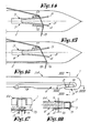
- Figs. 12 and 13 show a variant of the thread clamp 1 according to the invention, again used in a feed gripper 2.
- the first jaw 3 which forms part of the lever 13 instead of the second jaw 6.
- the spring arms 4 and 5 here consist of lamellae which extend freely from the end of the lever 13.
- the second jaw 6, or at least the wedge-shaped part of it, is solidly attached to the feed gripper 2.
- the operation is similar to that of the other variants described above.
- the use of the thread stops 16 and 17 has already been described with reference to the variant shown in figs. 1 to 3.
- Figs. 14 and 15 show yet another two variants of the thread stops, with the particular characteristic that the stops 16 and 17 are shifted with respect to the long axis of the thread clamp 1. This gives better clamping of the thread 18 in the direction in which the thread is stressed by the clamp.
- the stop 16 is formed by the body of the feed gripper 2.
- Figs. 16 to 18 show how a thread clamp 1 according to the invention is used in a receiving gripper 24.
- the construction is essentially similar to that of the embodiments already described.
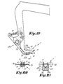
- Figs. 19 and 20 show yet another thread presentation arm 25 using a thread clamp 1 according to the invention.
- Such a thread presentation arm 25 can for instance form part of the thread presentation mechanism described in Dutch patent application No. 8600857 by the present applicant.
- the second jaw 6 may also consist of a a groove 26, eg. a V shape, whose sides 27 and 28 cooperate with the edges 14 and 15 of the spring arms 4 and 5 of the first jaw 3.
- This embodiment of the thread clamp 1 can of course be used in a feed gripper 2, receiving gripper 24 or thread presentation arm 25 as described above.
Applications Claiming Priority (2)
| Application Number | Priority Date | Filing Date | Title |
|---|---|---|---|
| BE8700341A BE1000448A4 (nl) | 1987-04-02 | 1987-04-02 | Draadklem. |
| BE8700341 | 1987-04-02 |
Publications (2)
| Publication Number | Publication Date |
|---|---|
| EP0285591A1 true EP0285591A1 (de) | 1988-10-05 |
| EP0285591B1 EP0285591B1 (de) | 1991-05-08 |
Family
ID=3882598
Family Applications (1)
| Application Number | Title | Priority Date | Filing Date |
|---|---|---|---|
| EP88870042A Expired EP0285591B1 (de) | 1987-04-02 | 1988-03-10 | Fadenklemme |
Country Status (4)
| Country | Link |
|---|---|
| US (1) | US4875505A (de) |
| EP (1) | EP0285591B1 (de) |
| BE (1) | BE1000448A4 (de) |
| DE (1) | DE3862668D1 (de) |
Cited By (3)
| Publication number | Priority date | Publication date | Assignee | Title |
|---|---|---|---|---|
| EP0571025A1 (de) * | 1992-05-22 | 1993-11-24 | NUOVOPIGNONE INDUSTRIE MECCANICHE E FONDERIA S.p.A. | Nehmergreifer für Webmaschinen |
| EP0576074A1 (de) * | 1992-06-23 | 1993-12-29 | NUOVOPIGNONE INDUSTRIE MECCANICHE E FONDERIA S.p.A. | Nehmergreifer für Webmaschinen |
| CN1099107C (zh) * | 1998-11-20 | 2003-01-15 | 阿尔派株式会社 | 盘夹紧机构和带有夹紧机构的盘播放机 |
Families Citing this family (3)
| Publication number | Priority date | Publication date | Assignee | Title |
|---|---|---|---|---|
| IT1226865B (it) * | 1988-08-19 | 1991-02-20 | Nuovo Pignone Spa | Perfezionamenti in una pinza passatrama di condotta per telai tessili senza navetta. |
| BE1014840A4 (nl) * | 2002-05-21 | 2004-05-04 | Wiele Michel Van De Nv | Grijper voor een axminstergrijperweefmachine. |
| BE1024494B1 (nl) * | 2016-08-11 | 2018-03-12 | Picanol Naamloze Vennootschap | Grijperband en grijpereenheid voor een grijperweefmachine |
Citations (3)
| Publication number | Priority date | Publication date | Assignee | Title |
|---|---|---|---|---|
| FR2087725A5 (de) * | 1970-05-29 | 1971-12-31 | Fabre Aime | |
| FR2202965A1 (de) * | 1972-10-12 | 1974-05-10 | Fabre Aime | |
| BE902141A (nl) * | 1985-04-09 | 1985-10-09 | Picanol Nv | Verbeterde grijpers voor weefmachines. |
Family Cites Families (4)
| Publication number | Priority date | Publication date | Assignee | Title |
|---|---|---|---|---|
| FR1444834A (fr) * | 1965-05-25 | 1966-07-08 | Alsacienne Constr Meca | Perfectionnement aux pinces de passe-trame pour métiers à tisser sans navette |
| CH508075A (de) * | 1970-06-04 | 1971-05-31 | Saurer Ag Adolph | Garnhalteeinrichtung an einem Schussfadeneintragsorgan einer Webmaschine |
| GB1405403A (en) * | 1974-03-26 | 1975-09-10 | Thomson Shpherd Co Ltd | Carpet looms |
| IT1167266B (it) * | 1983-10-07 | 1987-05-13 | Vamatex Spa | Organo di ritegno della trama in pinze portatrama per telai di tessitura |
-
1987
- 1987-04-02 BE BE8700341A patent/BE1000448A4/nl not_active IP Right Cessation
-
1988
- 1988-03-10 DE DE8888870042T patent/DE3862668D1/de not_active Expired - Lifetime
- 1988-03-10 EP EP88870042A patent/EP0285591B1/de not_active Expired
- 1988-03-18 US US07/170,011 patent/US4875505A/en not_active Expired - Lifetime
Patent Citations (3)
| Publication number | Priority date | Publication date | Assignee | Title |
|---|---|---|---|---|
| FR2087725A5 (de) * | 1970-05-29 | 1971-12-31 | Fabre Aime | |
| FR2202965A1 (de) * | 1972-10-12 | 1974-05-10 | Fabre Aime | |
| BE902141A (nl) * | 1985-04-09 | 1985-10-09 | Picanol Nv | Verbeterde grijpers voor weefmachines. |
Cited By (5)
| Publication number | Priority date | Publication date | Assignee | Title |
|---|---|---|---|---|
| EP0571025A1 (de) * | 1992-05-22 | 1993-11-24 | NUOVOPIGNONE INDUSTRIE MECCANICHE E FONDERIA S.p.A. | Nehmergreifer für Webmaschinen |
| US5341852A (en) * | 1992-05-22 | 1994-08-30 | Nuovopignone Industrie Meccaniche E Fonderia Spa | Taker gripper for loom use |
| EP0576074A1 (de) * | 1992-06-23 | 1993-12-29 | NUOVOPIGNONE INDUSTRIE MECCANICHE E FONDERIA S.p.A. | Nehmergreifer für Webmaschinen |
| US5348057A (en) * | 1992-06-23 | 1994-09-20 | Nuovopignone Industrie Meccahniche E Fonderia S.P.A. | Taker gripper in which the wedge moves axially within the hook |
| CN1099107C (zh) * | 1998-11-20 | 2003-01-15 | 阿尔派株式会社 | 盘夹紧机构和带有夹紧机构的盘播放机 |
Also Published As
| Publication number | Publication date |
|---|---|
| EP0285591B1 (de) | 1991-05-08 |
| DE3862668D1 (de) | 1991-06-13 |
| US4875505A (en) | 1989-10-24 |
| BE1000448A4 (nl) | 1988-12-06 |
Similar Documents
| Publication | Publication Date | Title |
|---|---|---|
| US4708174A (en) | Weft gripper for weaving machine | |
| EP0285591B1 (de) | Fadenklemme | |
| EP3060706B1 (de) | Vorrichtung zum abschneiden einer schussfadenlänge beim weben auf einer webmaschine und webmaschine mit solch einer vorrichtung | |
| CA1297510C (en) | Gripper-device for a printing machine | |
| US3220743A (en) | Gripping device | |
| DE2644343A1 (de) | Zubringergreifer fuer webmaschinen mit kontinuierlicher schussfadenzufuhr | |
| KR930023511A (ko) | 직기에 사용되는 개선된 테이커 그리퍼(taker gripper) | |
| KR930000371B1 (ko) | 북 없는 직기의 위사 반송 그리퍼 쌍 | |
| CA1091132A (en) | Drawing gripper for weaving looms | |
| US1238167A (en) | Rope or wire clamp. | |
| CN109415849B (zh) | 用于夹紧纬线的装置 | |
| US1148541A (en) | Lug-strap holder. | |
| CN1033850A (zh) | 一对用于无梭织机的纬纱夹挟器 | |
| US20020166600A1 (en) | Thread gripper for a rapier of a rapier loom | |
| US2579588A (en) | Ear ornament clasp | |
| EP0394749A1 (de) | Zubringergreifer mit axialem Schieber für schützenlose Webmaschinen | |
| US6453952B1 (en) | Thread gripper for a rapier of a rapier loom | |
| US3380483A (en) | Thread cutter and clamping mechanism for looms | |
| CN210975018U (zh) | 一种片梭纱夹 | |
| EP1426471B1 (de) | Bringergreifer für Webmaschinen | |
| US3200851A (en) | Thread parting and clamping mechanism | |
| KR100330283B1 (ko) | 위사반송그리퍼 | |
| SU1668503A1 (ru) | Захват подающей рапиры бесчелночного ткацкого станка | |
| SU697614A1 (ru) | Прокладчик уточной нити к ткацкому станку | |
| PL115625B2 (en) | Apparatus for introducing the weft into shed for needlelooms |
Legal Events
| Date | Code | Title | Description |
|---|---|---|---|
| PUAI | Public reference made under article 153(3) epc to a published international application that has entered the european phase |
Free format text: ORIGINAL CODE: 0009012 |
|
| AK | Designated contracting states |
Kind code of ref document: A1 Designated state(s): CH DE FR IT LI NL |
|
| 17P | Request for examination filed |
Effective date: 19881019 |
|
| 17Q | First examination report despatched |
Effective date: 19900806 |
|
| GRAA | (expected) grant |
Free format text: ORIGINAL CODE: 0009210 |
|
| AK | Designated contracting states |
Kind code of ref document: B1 Designated state(s): CH DE FR IT LI NL |
|
| ITF | It: translation for a ep patent filed |
Owner name: DR. ING. A. RACHELI & C. |
|
| REF | Corresponds to: |
Ref document number: 3862668 Country of ref document: DE Date of ref document: 19910613 |
|
| ET | Fr: translation filed | ||
| PLBE | No opposition filed within time limit |
Free format text: ORIGINAL CODE: 0009261 |
|
| STAA | Information on the status of an ep patent application or granted ep patent |
Free format text: STATUS: NO OPPOSITION FILED WITHIN TIME LIMIT |
|
| 26N | No opposition filed | ||
| PG25 | Lapsed in a contracting state [announced via postgrant information from national office to epo] |
Ref country code: NL Effective date: 19921001 |
|
| NLV4 | Nl: lapsed or anulled due to non-payment of the annual fee | ||
| PGFP | Annual fee paid to national office [announced via postgrant information from national office to epo] |
Ref country code: FR Payment date: 19990215 Year of fee payment: 12 |
|
| PGFP | Annual fee paid to national office [announced via postgrant information from national office to epo] |
Ref country code: DE Payment date: 19990222 Year of fee payment: 12 |
|
| PGFP | Annual fee paid to national office [announced via postgrant information from national office to epo] |
Ref country code: CH Payment date: 19990602 Year of fee payment: 12 |
|
| PG25 | Lapsed in a contracting state [announced via postgrant information from national office to epo] |
Ref country code: LI Free format text: LAPSE BECAUSE OF NON-PAYMENT OF DUE FEES Effective date: 20000331 Ref country code: CH Free format text: LAPSE BECAUSE OF NON-PAYMENT OF DUE FEES Effective date: 20000331 |
|
| REG | Reference to a national code |
Ref country code: CH Ref legal event code: PL |
|
| PG25 | Lapsed in a contracting state [announced via postgrant information from national office to epo] |
Ref country code: FR Free format text: LAPSE BECAUSE OF NON-PAYMENT OF DUE FEES Effective date: 20001130 |
|
| REG | Reference to a national code |
Ref country code: FR Ref legal event code: ST |
|
| PG25 | Lapsed in a contracting state [announced via postgrant information from national office to epo] |
Ref country code: DE Free format text: LAPSE BECAUSE OF NON-PAYMENT OF DUE FEES Effective date: 20010103 |
|
| PG25 | Lapsed in a contracting state [announced via postgrant information from national office to epo] |
Ref country code: IT Free format text: LAPSE BECAUSE OF NON-PAYMENT OF DUE FEES Effective date: 20050310 |