EP0285513A1 - Dispositifs de détection de transitions vers l'etat normal dans un bobinage supraconducteur, notamment de génératrice électrique, et de protection d'un tel bobinage - Google Patents
Dispositifs de détection de transitions vers l'etat normal dans un bobinage supraconducteur, notamment de génératrice électrique, et de protection d'un tel bobinage Download PDFInfo
- Publication number
- EP0285513A1 EP0285513A1 EP88400763A EP88400763A EP0285513A1 EP 0285513 A1 EP0285513 A1 EP 0285513A1 EP 88400763 A EP88400763 A EP 88400763A EP 88400763 A EP88400763 A EP 88400763A EP 0285513 A1 EP0285513 A1 EP 0285513A1
- Authority
- EP
- European Patent Office
- Prior art keywords
- winding
- generator
- normal state
- phase
- detecting
- Prior art date
- Legal status (The legal status is an assumption and is not a legal conclusion. Google has not performed a legal analysis and makes no representation as to the accuracy of the status listed.)
- Granted
Links
Images
Classifications
-
- H—ELECTRICITY
- H02—GENERATION; CONVERSION OR DISTRIBUTION OF ELECTRIC POWER
- H02H—EMERGENCY PROTECTIVE CIRCUIT ARRANGEMENTS
- H02H7/00—Emergency protective circuit arrangements specially adapted for specific types of electric machines or apparatus or for sectionalised protection of cable or line systems, and effecting automatic switching in the event of an undesired change from normal working conditions
- H02H7/001—Emergency protective circuit arrangements specially adapted for specific types of electric machines or apparatus or for sectionalised protection of cable or line systems, and effecting automatic switching in the event of an undesired change from normal working conditions for superconducting apparatus, e.g. coils, lines, machines
-
- Y—GENERAL TAGGING OF NEW TECHNOLOGICAL DEVELOPMENTS; GENERAL TAGGING OF CROSS-SECTIONAL TECHNOLOGIES SPANNING OVER SEVERAL SECTIONS OF THE IPC; TECHNICAL SUBJECTS COVERED BY FORMER USPC CROSS-REFERENCE ART COLLECTIONS [XRACs] AND DIGESTS
- Y02—TECHNOLOGIES OR APPLICATIONS FOR MITIGATION OR ADAPTATION AGAINST CLIMATE CHANGE
- Y02E—REDUCTION OF GREENHOUSE GAS [GHG] EMISSIONS, RELATED TO ENERGY GENERATION, TRANSMISSION OR DISTRIBUTION
- Y02E40/00—Technologies for an efficient electrical power generation, transmission or distribution
- Y02E40/60—Superconducting electric elements or equipment; Power systems integrating superconducting elements or equipment
-
- Y—GENERAL TAGGING OF NEW TECHNOLOGICAL DEVELOPMENTS; GENERAL TAGGING OF CROSS-SECTIONAL TECHNOLOGIES SPANNING OVER SEVERAL SECTIONS OF THE IPC; TECHNICAL SUBJECTS COVERED BY FORMER USPC CROSS-REFERENCE ART COLLECTIONS [XRACs] AND DIGESTS
- Y10—TECHNICAL SUBJECTS COVERED BY FORMER USPC
- Y10S—TECHNICAL SUBJECTS COVERED BY FORMER USPC CROSS-REFERENCE ART COLLECTIONS [XRACs] AND DIGESTS
- Y10S505/00—Superconductor technology: apparatus, material, process
- Y10S505/825—Apparatus per se, device per se, or process of making or operating same
- Y10S505/876—Electrical generator or motor structure
Definitions
- the present invention relates to a device for detecting conductor transitions from the superconductive state to the normal state in a superconductive coil at industrial frequency, in particular for an armature of an electric generator.
- the object of the present invention is to provide a device for detecting conductor transitions in superconductive coils which reacts immediately and which has high reliability, while remaining simple, and which allows effective protection of these coils against their destruction or damage. .
- the device according to the invention is characterized in that it comprises an auxiliary generator of a current of low intensity, of frequency notably higher than the industrial frequency, single-phase or multi-phase depending on whether the main current flowing through the windings is single-phase or multi-phase, mounted in parallel with the superconductive winding, and means for detecting the variation of the phase shift between intensity and voltage of the auxiliary current when the conductors of the winding pass to the normal state.
- the means for detecting the variation in the phase shift preferably consist of a decoupling capacity in series with the auxiliary current generator, of such value relative to the reverse inductance of the winding that it corresponds to the resonance at the frequency of the auxiliary current. , and by means for detecting the appearance of a voltage across the terminals of the generator of the auxiliary current.
- the device also advantageously comprises a plug circuit for the frequency of the auxiliary current placed between the auxiliary generator and the network supplied by the main generator, so as to protect the network from disturbances that could result from the measurement currents.
- a first device for protecting an industrial frequency superconductive winding against excessive heating resulting from the passage of the conductors of the winding to the normal state, comprises a switch controlled by the detection device as defined above, and in addition a triac mounted in series with a discharge resistance and arranged in parallel with the winding to be protected, this triac also being controlled by the detection device.
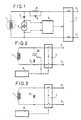
- Figure 1 shows the principle of detection.
- An auxiliary generator 4 of a low intensity current, of the order of less than 1/100 of the current intensity of the main circuit, and of frequency is superimposed on the main generator 1 of three-phase current at 50 or 60 Hz. higher f1, for example of an order of magnitude 10 to 20 times higher than that of the industrial frequency.
- the main generator with superconductive winding supplies the terminals 2 and 3 of the operating circuit through a circuit breaker 7.
- the generator 1 at this frequency is represented only by its inverse inductance Li without electromotive force.
- the phase shift between the current and the voltage at this frequency does not depend on the load of the generator as it is the case for the main system at 50 or 60 Hz; it is fixed only by the passive elements inductance Li and capacitance C.
- the detection of transitions in the winding conductors will be carried out by detecting the change in phase shift between the current and the auxiliary voltage.
- FIG. 2 represents a protection device in which the detection of a transition ensures the tripping of a triac 10 arranged in parallel with the armature of the main generator associated with a discharge resistor 11.
- the tripping of this triac can be caused before or at the same time as the opening of the main circuit breaker 7.
Abstract
Description
- La présente invention concerne un dispositif de détection de transitions de conducteurs de l'état supraconducteur à l'état normal dans un bobinage supraconducteur à fréquence industrielle, notamment pour induit de génératrice électrique.
- Elle s'étend en outre à un dispositif de protection d'un tel bobinage faisant appel à un tel dispositif de détection.
- Compte tenu du caractère extrêmement rapide du passage d'un supraconducteur à l'état normal dans le cas de l'apparition d'un défaut, il convient d'assurer une détection également très rapide pour couper ou limiter le courant afin d'éviter la destruction de ces bobinages.
- Un moyen de détecter de telles transitions serait d'observer le déphasage entre le courant et la tension, qui varie fortement lorsque les conducteurs du bobinage repassent à l'état normal. Une telle détection est toutefois assez peu fiable, car ce déphasage dépend de la charge de la génératrice.
- La présente invention a pour but de procurer un dispositif de détection de transitions de conducteurs dans des bobinages supraconducteurs qui réagisse immédiatement et qui présente une fiabilité élevée, tout en restant simple, et qui permette une protection efficace de ces bobinages contre leur destruction ou leur endommagement.
- Le dispositif selon l'invention est caractérisé en qu'il comporte une génératrice auxiliaire d'un courant de faible intensité, de fréquence notablement plus élevée que la fréquence industrielle, monophasé ou polyphasé selon que le courant principal parcourant les bobinages est monophasé ou polyphasé, montée en parallèle avec le bobinage supraconducteur, et des moyens pour détecter la variation du déphasage entre intensité et tension du courant auxiliaire lorsque des conducteurs du bobinage passent à l'état normal.
- Les moyens pour détecter la variation du déphasage sont constitués de préférence par une capacité de découplage en série avec la génératrice de courant auxiliaire, de valeur telle relativement à l'inductance inverse du bobinage qu'elle corresponde à la résonance à la fréquence du courant auxiliaire, et par des moyens pour détecter l'apparition d'une tension aux bornes de la génératrice du courant auxiliaire.
- Le dispositif comprend en outre avantageusement un circuit bouchon pour la fréquence du courant auxiliaire disposé entre la génératrice auxiliaire et le réseau alimenté par la génératrice principale, de façon à protéger le réseau des perturbations que pourraient entraîner les courants de mesure.
- Un premier dispositif selon l'invention de protection d'un bobinage supraconducteur à fréquence industrielle contre un échauffement excessif résultant du passage de conducteurs du bobinage à l'état normal, comprend un interrupteur commandé par le dispositif de détection tel que défini ci-dessus, et en outre un triac monté en série avec une résistance de décharge et disposé en parallèle avec le bobinage à protéger, ce triac étant aussi commandé par le dispositif de détection.
- Un autre dispositif selon l'invention de protection d'un bobinage supraconducteur à fréquence industrielle comprend un interrupteur commandé par le dispositif de détection et en outre une varistance en parallèle avec le bobinage à protéger.
- Il est décrit ci-après, à titre d'exemples et en référence aux figures du dessin annexé, un dispositif de détection de transitions de conducteurs dans un bobinage supraconducteur de machine synchrone et des dispositifs de protection commandés par un tel dispositif de détection.
- La figure 1 représente un dispositif de détection de transitions dans un induit de machine synchrone à bobinage supraconducteur.
- La figure 2 représente un dispositif de protection à triac.
- La figure 3 représente un dispositif de protection à varistance.
- La figure 1 représente le principe de la détection. On superpose à la génératrice principale 1 de courant triphasé à 50 ou 60 Hz une génératrice auxiliaire 4 d'un courant de faible intensité, de l'ordre de moins de 1/100 de l'intensité du courant du circuit principal, et de fréquence supérieure f1, par exemple d'un ordre de grandeur 10 à 20 fois plus élevé que celui de la fréquence industrielle. La génératrice principale à bobinage supraconducteur alimente les bornes 2 et 3 du circuit d'utilisation à travers un disjoncteur 7. La génératrice 1 à cette fréquence est représentée uniquement par son inductance inverse Li sans force électromotrice. Ainsi le déphasage entre le courant et la tension à cette fréquence ne dépend pas de la charge de la génératrice comme c'est le cas pour le système principal à 50 ou 60 Hz ; il est fixé uniquement par les éléments passifs inductance Li et capacitance C.
- Si en plus on choisit la capacité de découplage C1 du condensateur 5 en série avec la génératrice auxiliaire 4 pour obtenir la résonance (de façon que Li C1 (2 π f1)² = 1), la transition d'une phase se traduit par l'apparition d'une tension aux bornes de la source de courant correspondante. Cette tension détectée par le détecteur de tension 6 est transmise au disjoncteur 7, qui ouvre le circuit alimentant les bornes 2, 3 du réseau d'utilisation.
- Pour protéger le réseau des perturbations que pourraient entraîner les courants de mesure, on dispose entre la génératrice principale et le réseau un circuit bouchon pour la fréquence f1, formé de l'inductance 8 et de la capacitance 9.
- Si on n'est pas à la résonance entre l'inductance inverse de la génératrice principale et la capacité en série avec la génératrice auxiliaire, la détection de transitions dans les conducteurs des bobinages s'effectuera par la détection du changement de déphasage entre le courant et la tension auxiliaire.
- La protection proprement dite du bobinage supraconducteur alternatif ne peut pas être assurée par une résistance de décharge classique, à cause des pertes importantes en régime de fonctionnement normal dues à la tension aux bornes du bobinage.
- La figure 2 représente un dispositif de protection dans lequel la détection d'une transition assure le déclenchement d'un triac 10 disposé en parallèle avec l'induit de la génératrice principale associé à une résistance de décharge 11. Le déclenchement de ce triac peut être provoqué avant ou en même temps que l'ouverture du disjoncteur principal 7.
- On peut aussi assurer la protection du bobinage supraconducteur comme représentée en figure 3, à l'aide d'une varistance 12, disposée en parallèle avec les bobinages à protéger.
Claims (5)
Priority Applications (1)
| Application Number | Priority Date | Filing Date | Title |
|---|---|---|---|
| AT88400763T ATE82442T1 (de) | 1987-03-30 | 1988-03-29 | Einrichtungen zur feststellung des uebergangs in den normalzustand in einer supraleitenden wicklung, insbesondere eines elektrischen generators und einrichtung zum schutz einer derartigen wicklung. |
Applications Claiming Priority (2)
| Application Number | Priority Date | Filing Date | Title |
|---|---|---|---|
| FR8704404A FR2613493B1 (fr) | 1987-03-30 | 1987-03-30 | Dispositifs de detection de transitions vers l'etat normal dans un bobinage supraconducteur, notamment de generatrice electrique, et de protection d'un tel bobinage |
| FR8704404 | 1987-03-30 |
Publications (2)
| Publication Number | Publication Date |
|---|---|
| EP0285513A1 true EP0285513A1 (fr) | 1988-10-05 |
| EP0285513B1 EP0285513B1 (fr) | 1992-11-11 |
Family
ID=9349564
Family Applications (1)
| Application Number | Title | Priority Date | Filing Date |
|---|---|---|---|
| EP88400763A Expired - Lifetime EP0285513B1 (fr) | 1987-03-30 | 1988-03-29 | Dispositifs de détection de transitions vers l'etat normal dans un bobinage supraconducteur, notamment de génératrice électrique, et de protection d'un tel bobinage |
Country Status (7)
| Country | Link |
|---|---|
| US (1) | US4855859A (fr) |
| EP (1) | EP0285513B1 (fr) |
| AT (1) | ATE82442T1 (fr) |
| DE (1) | DE3875771T2 (fr) |
| ES (1) | ES2035932T3 (fr) |
| FR (1) | FR2613493B1 (fr) |
| GR (1) | GR3006796T3 (fr) |
Cited By (2)
| Publication number | Priority date | Publication date | Assignee | Title |
|---|---|---|---|---|
| EP0415712A2 (fr) * | 1989-08-31 | 1991-03-06 | Westinghouse Electric Corporation | Détecteur supraconducteur pour la surveillance de la transition de la supra-conductivité à la conductivité dans un supraconducteur |
| EP0817348A2 (fr) * | 1996-06-25 | 1998-01-07 | Oxford Instruments Plc | Dispositif limiteur de courant |
Families Citing this family (9)
| Publication number | Priority date | Publication date | Assignee | Title |
|---|---|---|---|---|
| US5210674A (en) * | 1990-05-31 | 1993-05-11 | Mitsubishi Denki Kabushiki Kaisha | Superconducting coil protective system |
| JP2831516B2 (ja) * | 1992-09-21 | 1998-12-02 | 株式会社日立製作所 | 超電導エネルギー貯蔵装置 |
| US5644218A (en) * | 1995-02-01 | 1997-07-01 | Superconductivity, Inc. | Protection device for a superconducting coil of a superconducting voltage stabilizer |
| GB9506096D0 (en) * | 1995-03-24 | 1995-05-10 | Oxford Instr Public Limited Co | Current limiting device |
| US5862028A (en) * | 1996-05-24 | 1999-01-19 | Northrop Grumman Corporation | Method and apparatus for detecting quenching of a coil for a superconducting magnet |
| GB9621142D0 (en) | 1996-10-10 | 1996-11-27 | Oxford Instr Public Limited Co | Current limiting device |
| US7048717B1 (en) * | 1999-09-27 | 2006-05-23 | Essex Technology, Inc. | Rotate-to-advance catheterization system |
| JP4689413B2 (ja) * | 2005-09-05 | 2011-05-25 | 財団法人電力中央研究所 | 超電導導体のクエンチ検出方法並びに装置 |
| FR2923648B1 (fr) * | 2007-11-12 | 2009-12-18 | Commissariat Energie Atomique | Systeme de creation d'un champ magnetique via un aimant supra-conducteur |
Citations (2)
| Publication number | Priority date | Publication date | Assignee | Title |
|---|---|---|---|---|
| FR2224909A1 (en) * | 1973-04-03 | 1974-10-31 | Cem Comp Electro Mec | Super or hyper conductive element protection - detects phase angle variations between current and voltage |
| US4375659A (en) * | 1981-09-21 | 1983-03-01 | General Dynamics Corporation/Convair Div. | Electronic circuit for the detection and analysis of normal zones in a superconducting coil |
Family Cites Families (7)
| Publication number | Priority date | Publication date | Assignee | Title |
|---|---|---|---|---|
| US4021703A (en) * | 1975-06-02 | 1977-05-03 | Westinghouse Electric Corporation | Phase imbalance detection circuit |
| DE2839787A1 (de) * | 1978-09-13 | 1980-03-27 | Kernforschungsz Karlsruhe | Quench-detektor |
| JPS56150805A (en) * | 1980-04-24 | 1981-11-21 | Hitachi Ltd | Protective device of superconducting coil |
| US4451823A (en) * | 1981-08-07 | 1984-05-29 | Dart Controls, Inc. | Overload sensing circuit for a motor |
| JPS60130107A (ja) * | 1983-12-19 | 1985-07-11 | Toshiba Corp | 超電導保護回路 |
| EP0205924A3 (fr) * | 1985-05-20 | 1988-04-06 | Kabushiki Kaisha Toshiba | Système de surveillance pour détecter la transition de la supraconductivité à la conductivité de bobines supraconductrices |
| US4703387A (en) * | 1986-05-22 | 1987-10-27 | Franklin Electric Co., Inc. | Electric motor underload protection system |
-
1987
- 1987-03-30 FR FR8704404A patent/FR2613493B1/fr not_active Expired
-
1988
- 1988-03-29 ES ES198888400763T patent/ES2035932T3/es not_active Expired - Lifetime
- 1988-03-29 DE DE8888400763T patent/DE3875771T2/de not_active Expired - Fee Related
- 1988-03-29 EP EP88400763A patent/EP0285513B1/fr not_active Expired - Lifetime
- 1988-03-29 AT AT88400763T patent/ATE82442T1/de not_active IP Right Cessation
- 1988-03-30 US US07/175,441 patent/US4855859A/en not_active Expired - Fee Related
-
1993
- 1993-01-14 GR GR930400051T patent/GR3006796T3/el unknown
Patent Citations (2)
| Publication number | Priority date | Publication date | Assignee | Title |
|---|---|---|---|---|
| FR2224909A1 (en) * | 1973-04-03 | 1974-10-31 | Cem Comp Electro Mec | Super or hyper conductive element protection - detects phase angle variations between current and voltage |
| US4375659A (en) * | 1981-09-21 | 1983-03-01 | General Dynamics Corporation/Convair Div. | Electronic circuit for the detection and analysis of normal zones in a superconducting coil |
Non-Patent Citations (1)
| Title |
|---|
| PATENT ABSTRACTS OF JAPAN, vol. 9, no. 288 (E-358)[2011], 15 novembre 1985, page 132 E 358; & JP-A-60 130 107 (TOSHIBA K.K.) 11-07-1985 * |
Cited By (5)
| Publication number | Priority date | Publication date | Assignee | Title |
|---|---|---|---|---|
| EP0415712A2 (fr) * | 1989-08-31 | 1991-03-06 | Westinghouse Electric Corporation | Détecteur supraconducteur pour la surveillance de la transition de la supra-conductivité à la conductivité dans un supraconducteur |
| EP0415712A3 (en) * | 1989-08-31 | 1991-08-14 | Westinghouse Electric Corporation | A superconducting sensor for quench detection in a superconductor |
| EP0817348A2 (fr) * | 1996-06-25 | 1998-01-07 | Oxford Instruments Plc | Dispositif limiteur de courant |
| EP0817348A3 (fr) * | 1996-06-25 | 1999-04-07 | Oxford Instruments Plc | Dispositif limiteur de courant |
| US6236545B1 (en) | 1996-06-25 | 2001-05-22 | Oxford Instruments Plc | Current limiting device utilizing a superconductor |
Also Published As
| Publication number | Publication date |
|---|---|
| GR3006796T3 (fr) | 1993-06-30 |
| ES2035932T3 (es) | 1993-05-01 |
| DE3875771T2 (de) | 1993-03-25 |
| DE3875771D1 (de) | 1992-12-17 |
| US4855859A (en) | 1989-08-08 |
| ATE82442T1 (de) | 1992-11-15 |
| EP0285513B1 (fr) | 1992-11-11 |
| FR2613493B1 (fr) | 1989-06-23 |
| FR2613493A1 (fr) | 1988-10-07 |
Similar Documents
| Publication | Publication Date | Title |
|---|---|---|
| EP0407310B1 (fr) | Déclencheur statique comportant un système de désensibilisation de la protection terre | |
| EP0396477B1 (fr) | Déclencheur statique pour un disjoncteur de protection d'un réseau triphase, permettant la détection du type de défaut | |
| EP0205149B1 (fr) | Dispositif de protection d'une ligne électrique d'énergie contre des surtensions transitoires élevées | |
| EP0285513B1 (fr) | Dispositifs de détection de transitions vers l'etat normal dans un bobinage supraconducteur, notamment de génératrice électrique, et de protection d'un tel bobinage | |
| EP1612904A2 (fr) | Système et procédé pour la protection d'un supraconducteur lors d'une transition de l'état supraconducteur à l'état normal | |
| FR2721448A1 (fr) | Circuit de commande pour un générateur électrique. | |
| FR2494056A1 (fr) | Generateur d'energie electrique a alternateur pour vehicules automobiles avec protection contre les phenomenes transitoires dus a la deconnexion de la batterie | |
| US5418675A (en) | Protection system for AC generators | |
| FR2618276A1 (fr) | Dispositif de commutation electronique. | |
| Solovev | Instrument current transducer for protective relaying systems | |
| EP0252493B1 (fr) | Dispositif de protection d'une ligne électrique d'énergie contre ses surtensions transitoires élevées | |
| JPH05500745A (ja) | 電源装置 | |
| EP0900464B1 (fr) | Reduction des harmoniques dans des machines a courant alternatif | |
| EP1183764B1 (fr) | Systeme de protection contre les fuites a la terre d'un bobinage de machine electrique | |
| EP0075357B1 (fr) | Circuit d'alimentation d'une machine électrique asynchrone polyphasée | |
| Graham et al. | Generator protection with a new static negative sequence relay | |
| EP1183763B1 (fr) | Systeme de protection contre les fuites a la terre pour enroulement de machine electrique | |
| CA2467106A1 (fr) | Detecteur de mise a la terre pour bobinages | |
| FR2775847A1 (fr) | Dispositifs de protection differentielle, appareil electrique et installation electrique comportant un tel dispositif | |
| EP0231746B1 (fr) | Chargeur de bobine supraconductrice | |
| EP0813283B1 (fr) | Dispositif de protection différentielle immunisé contre les déclenchements intempestifs | |
| EP1215793A2 (fr) | Suppression de tensions transitoires | |
| FR2709616A1 (fr) | Disjoncteur différentiel et parasurtenseur. | |
| BE647635A (fr) | ||
| SU997168A1 (ru) | Устройство дл защиты трехфазного электродвигател , соединенного в звезду, от обрыва фазы |
Legal Events
| Date | Code | Title | Description |
|---|---|---|---|
| PUAI | Public reference made under article 153(3) epc to a published international application that has entered the european phase |
Free format text: ORIGINAL CODE: 0009012 |
|
| AK | Designated contracting states |
Kind code of ref document: A1 Designated state(s): AT BE CH DE ES FR GB GR IT LI LU NL SE |
|
| 17P | Request for examination filed |
Effective date: 19890403 |
|
| RAP1 | Party data changed (applicant data changed or rights of an application transferred) |
Owner name: GEC ALSTHOM SA |
|
| 17Q | First examination report despatched |
Effective date: 19910206 |
|
| GRAA | (expected) grant |
Free format text: ORIGINAL CODE: 0009210 |
|
| AK | Designated contracting states |
Kind code of ref document: B1 Designated state(s): AT BE CH DE ES FR GB GR IT LI LU NL SE |
|
| REF | Corresponds to: |
Ref document number: 82442 Country of ref document: AT Date of ref document: 19921115 Kind code of ref document: T |
|
| REF | Corresponds to: |
Ref document number: 3875771 Country of ref document: DE Date of ref document: 19921217 |
|
| GBT | Gb: translation of ep patent filed (gb section 77(6)(a)/1977) |
Effective date: 19921208 |
|
| ITF | It: translation for a ep patent filed |
Owner name: JACOBACCI CASETTA & PERANI S.P.A. |
|
| REG | Reference to a national code |
Ref country code: ES Ref legal event code: FG2A Ref document number: 2035932 Country of ref document: ES Kind code of ref document: T3 |
|
| REG | Reference to a national code |
Ref country code: GR Ref legal event code: FG4A Free format text: 3006796 |
|
| PLBE | No opposition filed within time limit |
Free format text: ORIGINAL CODE: 0009261 |
|
| STAA | Information on the status of an ep patent application or granted ep patent |
Free format text: STATUS: NO OPPOSITION FILED WITHIN TIME LIMIT |
|
| 26N | No opposition filed | ||
| EPTA | Lu: last paid annual fee | ||
| EAL | Se: european patent in force in sweden |
Ref document number: 88400763.4 |
|
| PGFP | Annual fee paid to national office [announced via postgrant information from national office to epo] |
Ref country code: GB Payment date: 19970213 Year of fee payment: 10 |
|
| PGFP | Annual fee paid to national office [announced via postgrant information from national office to epo] |
Ref country code: FR Payment date: 19970214 Year of fee payment: 10 |
|
| PGFP | Annual fee paid to national office [announced via postgrant information from national office to epo] |
Ref country code: BE Payment date: 19970217 Year of fee payment: 10 |
|
| PGFP | Annual fee paid to national office [announced via postgrant information from national office to epo] |
Ref country code: DE Payment date: 19970220 Year of fee payment: 10 Ref country code: AT Payment date: 19970220 Year of fee payment: 10 |
|
| PGFP | Annual fee paid to national office [announced via postgrant information from national office to epo] |
Ref country code: SE Payment date: 19970221 Year of fee payment: 10 |
|
| PGFP | Annual fee paid to national office [announced via postgrant information from national office to epo] |
Ref country code: NL Payment date: 19970224 Year of fee payment: 10 |
|
| PGFP | Annual fee paid to national office [announced via postgrant information from national office to epo] |
Ref country code: CH Payment date: 19970226 Year of fee payment: 10 |
|
| PGFP | Annual fee paid to national office [announced via postgrant information from national office to epo] |
Ref country code: GR Payment date: 19970228 Year of fee payment: 10 |
|
| PGFP | Annual fee paid to national office [announced via postgrant information from national office to epo] |
Ref country code: ES Payment date: 19970321 Year of fee payment: 10 |
|
| PGFP | Annual fee paid to national office [announced via postgrant information from national office to epo] |
Ref country code: LU Payment date: 19970408 Year of fee payment: 10 |
|
| PG25 | Lapsed in a contracting state [announced via postgrant information from national office to epo] |
Ref country code: LU Free format text: LAPSE BECAUSE OF NON-PAYMENT OF DUE FEES Effective date: 19980329 Ref country code: GB Free format text: LAPSE BECAUSE OF NON-PAYMENT OF DUE FEES Effective date: 19980329 Ref country code: AT Free format text: LAPSE BECAUSE OF NON-PAYMENT OF DUE FEES Effective date: 19980329 |
|
| PG25 | Lapsed in a contracting state [announced via postgrant information from national office to epo] |
Ref country code: SE Free format text: LAPSE BECAUSE OF NON-PAYMENT OF DUE FEES Effective date: 19980330 Ref country code: ES Free format text: LAPSE BECAUSE OF EXPIRATION OF PROTECTION Effective date: 19980330 |
|
| PG25 | Lapsed in a contracting state [announced via postgrant information from national office to epo] |
Ref country code: LI Free format text: LAPSE BECAUSE OF NON-PAYMENT OF DUE FEES Effective date: 19980331 Ref country code: GR Free format text: LAPSE BECAUSE OF NON-PAYMENT OF DUE FEES Effective date: 19980331 Ref country code: FR Free format text: THE PATENT HAS BEEN ANNULLED BY A DECISION OF A NATIONAL AUTHORITY Effective date: 19980331 Ref country code: CH Free format text: LAPSE BECAUSE OF NON-PAYMENT OF DUE FEES Effective date: 19980331 Ref country code: BE Free format text: LAPSE BECAUSE OF NON-PAYMENT OF DUE FEES Effective date: 19980331 |
|
| BERE | Be: lapsed |
Owner name: S.A. GEC ALSTHOM Effective date: 19980331 |
|
| PG25 | Lapsed in a contracting state [announced via postgrant information from national office to epo] |
Ref country code: NL Free format text: LAPSE BECAUSE OF NON-PAYMENT OF DUE FEES Effective date: 19981001 |
|
| REG | Reference to a national code |
Ref country code: CH Ref legal event code: PL |
|
| GBPC | Gb: european patent ceased through non-payment of renewal fee |
Effective date: 19980329 |
|
| NLV4 | Nl: lapsed or anulled due to non-payment of the annual fee |
Effective date: 19981001 |
|
| PG25 | Lapsed in a contracting state [announced via postgrant information from national office to epo] |
Ref country code: DE Free format text: LAPSE BECAUSE OF NON-PAYMENT OF DUE FEES Effective date: 19981201 |
|
| EUG | Se: european patent has lapsed |
Ref document number: 88400763.4 |
|
| REG | Reference to a national code |
Ref country code: FR Ref legal event code: ST |
|
| REG | Reference to a national code |
Ref country code: ES Ref legal event code: FD2A Effective date: 20000301 |
|
| PG25 | Lapsed in a contracting state [announced via postgrant information from national office to epo] |
Ref country code: IT Free format text: LAPSE BECAUSE OF NON-PAYMENT OF DUE FEES;WARNING: LAPSES OF ITALIAN PATENTS WITH EFFECTIVE DATE BEFORE 2007 MAY HAVE OCCURRED AT ANY TIME BEFORE 2007. THE CORRECT EFFECTIVE DATE MAY BE DIFFERENT FROM THE ONE RECORDED. Effective date: 20050329 |