EP0285378B1 - Stapelbarer Gitterrost - Google Patents
Stapelbarer Gitterrost Download PDFInfo
- Publication number
- EP0285378B1 EP0285378B1 EP88302800A EP88302800A EP0285378B1 EP 0285378 B1 EP0285378 B1 EP 0285378B1 EP 88302800 A EP88302800 A EP 88302800A EP 88302800 A EP88302800 A EP 88302800A EP 0285378 B1 EP0285378 B1 EP 0285378B1
- Authority
- EP
- European Patent Office
- Prior art keywords
- strips
- grid structure
- strip
- cut
- grid
- Prior art date
- Legal status (The legal status is an assumption and is not a legal conclusion. Google has not performed a legal analysis and makes no representation as to the accuracy of the status listed.)
- Expired - Lifetime
Links
- 239000000463 material Substances 0.000 title claims abstract description 19
- 210000004027 cell Anatomy 0.000 claims abstract description 35
- 210000002421 cell wall Anatomy 0.000 claims abstract description 34
- 229920003023 plastic Polymers 0.000 claims description 13
- 239000004033 plastic Substances 0.000 claims description 13
- 239000004698 Polyethylene Substances 0.000 claims description 2
- -1 polyethylene Polymers 0.000 claims description 2
- 229920000573 polyethylene Polymers 0.000 claims description 2
- 239000002689 soil Substances 0.000 abstract description 17
- 238000000034 method Methods 0.000 description 6
- 239000004576 sand Substances 0.000 description 4
- 238000003466 welding Methods 0.000 description 3
- 238000010276 construction Methods 0.000 description 2
- 230000004888 barrier function Effects 0.000 description 1
- 239000006229 carbon black Substances 0.000 description 1
- 230000015556 catabolic process Effects 0.000 description 1
- 238000006731 degradation reaction Methods 0.000 description 1
- 239000004744 fabric Substances 0.000 description 1
- 229920002457 flexible plastic Polymers 0.000 description 1
- 230000002452 interceptive effect Effects 0.000 description 1
- 230000014759 maintenance of location Effects 0.000 description 1
- 238000012986 modification Methods 0.000 description 1
- 230000004048 modification Effects 0.000 description 1
- 239000002245 particle Substances 0.000 description 1
- 239000011435 rock Substances 0.000 description 1
- XLYOFNOQVPJJNP-UHFFFAOYSA-N water Substances O XLYOFNOQVPJJNP-UHFFFAOYSA-N 0.000 description 1
Images

Classifications
-
- E—FIXED CONSTRUCTIONS
- E04—BUILDING
- E04C—STRUCTURAL ELEMENTS; BUILDING MATERIALS
- E04C1/00—Building elements of block or other shape for the construction of parts of buildings
- E04C1/39—Building elements of block or other shape for the construction of parts of buildings characterised by special adaptations, e.g. serving for locating conduits, for forming soffits, cornices, or shelves, for fixing wall-plates or door-frames, for claustra
- E04C1/395—Building elements of block or other shape for the construction of parts of buildings characterised by special adaptations, e.g. serving for locating conduits, for forming soffits, cornices, or shelves, for fixing wall-plates or door-frames, for claustra for claustra, fences, planting walls, e.g. sound-absorbing
-
- E—FIXED CONSTRUCTIONS
- E02—HYDRAULIC ENGINEERING; FOUNDATIONS; SOIL SHIFTING
- E02D—FOUNDATIONS; EXCAVATIONS; EMBANKMENTS; UNDERGROUND OR UNDERWATER STRUCTURES
- E02D29/00—Independent underground or underwater structures; Retaining walls
- E02D29/02—Retaining or protecting walls
-
- E—FIXED CONSTRUCTIONS
- E02—HYDRAULIC ENGINEERING; FOUNDATIONS; SOIL SHIFTING
- E02D—FOUNDATIONS; EXCAVATIONS; EMBANKMENTS; UNDERGROUND OR UNDERWATER STRUCTURES
- E02D29/00—Independent underground or underwater structures; Retaining walls
- E02D29/02—Retaining or protecting walls
- E02D29/0208—Gabions
-
- E—FIXED CONSTRUCTIONS
- E02—HYDRAULIC ENGINEERING; FOUNDATIONS; SOIL SHIFTING
- E02D—FOUNDATIONS; EXCAVATIONS; EMBANKMENTS; UNDERGROUND OR UNDERWATER STRUCTURES
- E02D29/00—Independent underground or underwater structures; Retaining walls
- E02D29/02—Retaining or protecting walls
- E02D29/0258—Retaining or protecting walls characterised by constructional features
- E02D29/0266—Retaining or protecting walls characterised by constructional features made up of preformed elements
-
- Y—GENERAL TAGGING OF NEW TECHNOLOGICAL DEVELOPMENTS; GENERAL TAGGING OF CROSS-SECTIONAL TECHNOLOGIES SPANNING OVER SEVERAL SECTIONS OF THE IPC; TECHNICAL SUBJECTS COVERED BY FORMER USPC CROSS-REFERENCE ART COLLECTIONS [XRACs] AND DIGESTS
- Y10—TECHNICAL SUBJECTS COVERED BY FORMER USPC
- Y10T—TECHNICAL SUBJECTS COVERED BY FORMER US CLASSIFICATION
- Y10T428/00—Stock material or miscellaneous articles
- Y10T428/24—Structurally defined web or sheet [e.g., overall dimension, etc.]
- Y10T428/24149—Honeycomb-like
- Y10T428/24157—Filled honeycomb cells [e.g., solid substance in cavities, etc.]
Definitions
- the present invention relates to a grid structure which can be stacked up and filled with soil to create free standing walls and similar structures.
- a grid structure comprising a repeating pattern of cells which are open at the top and bottom and used for soil confinement to provide a road base made from soils (sand, rounded rock, poorly graded aggregate, concrete, and the like) has been known and used for some time.
- a prime example is "Geoweb” (Trade Mark) plastic grid soil confinement system sold by Presto Products, Incorporated, P.O. Box 2399, Appleton, Wisconsin 54913 and disclosed in a booklet entitled "Geoweb Grid Confinement System” available from Presto Products, Incorporated.
- “Geoweb” grid cells are made from plastic strips which are joined on their faces in a side by side relationship at alternating spacings so that when the strips are stretched out in a direction perpendicular to the faces of the strips, the resulting grid section is honeycomb-like in appearance, with sinusoidal or undulent shaped cells.
- Voluminous reports have praised the ability of "Geoweb” grid cell material to support roadways.
- "Geoweb” grid cells have also been used in applications where one grid layer is stacked on another, such as a stepped back design for hill slope retention. Even free standing walls have been built with “Geoweb” grid cells.
- the cells are open at the top and bottom, there is a tendency for fill material to leak out of the cells if the cell below is not properly positioned. Also, the exposed soil in a cell not adequately covered is subject to being blown away by the wind.
- the present invention is characterised in that the cell walls of the grid structure have regions of differing height such that at least a part of the top edge of the cell wall on the perimeter of a lower layer of a grid structure overlaps at least a part of the bottom edge of the cell wall of the perimeter of an upper layer of a grid structure on top of the lower layer when the internal cell walls of the upper layer rest on top of the internal cell walls of the lower layer.
- the grid structure can be used in repeated layers without the need for intermediate sheet material, and significantly reduces exposure to or leakage from material in the perimeter cells.
- the grid structure makes it simple to build a wall or other free standing structure without exposed tops and bottoms of cells on the perimeter faces of the structure.
- Figure 1 depicts a wall being constructed with stackable soil confinement grid structures 10.
- the grid structure 10 is comprised of a plurality of strips of plastic 20 which are bonded together, one strip to the next, at alternating and equally spaced bonding areas.
- each layer of grid structure 10 is made of an even number of uniformly thick plastic strips 20 in side by side relationship, bonded by ultrasonic welding.
- the regions of differing height of the inside strips 22 differ in their pattern from the outside strips 24, as more fully described hereafter.
- the bonding between strips may best be described by thinking of the strips as being paired, starting with an outside strip 24 paired to an outermost inside strip 22, a pair of the next two inside strips 22, and so on.
- Each such pair is bonded at a bonding area constituting an end weld 32 adjacent to the end 34 of each strip 20.
- a short tail 36 between the end 34 of the strip 20 and the end weld 32 is provided to stabilize segments of the strip 20 adjacent to the outside weld 32.
- Each pair of strips is welded together at additional bonding areas 14, creating equal length strip segments between the end welds 32.
- one strip 20 from each adjacent pair of strips is also welded together at positions intermediate each of the welds in the pairs of strips, referred to hereafter as non-pair bonding areas 16.
- non-pair bonding areas 16 positions intermediate each of the welds in the pairs of strips.
- Each cell 40 has a cell wall made from one strip 20 and a cell wall made from a different strip 20.
- each strip 20 forms one wall of a cell on the perimeter of the grid structure 10.
- the lowermost or base grid structure 12 of a stack is designed to rest on a flat surface ( Figure 1). Since it has no grid structure layer 10 below it with which it needs to align, the bottom edge of each strip 20 in the base structure layer 12 is uniformly even. However, in many instances a grid structure layer 10 would be suitable as the bottom layer of a stack.
- the base structure layer 12 has inside strips 26 and outside strips 28 which differ from each other just as the inside strips 22 and outside strips 24 of the layer 10 differ from each other.
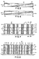
- Figures 3 to 6 respectively are plan views of the inside and outside strips 22, 24, 26 and 28, showing the shapes of these strips.
- the inside strip 22 ( Figure 3) used for grid structure layers 10 has a central cut-out section 42 which is a predetermined distance below the upstanding edge section 44 adjacent to the ends 34 of the strip 22.
- the central section 42 extends just beyond the region of the outermost non-pair bonding area 16.
- the bonding areas 14 are about 33 cm (13 inches) apart on each strip, as are the non-pair bonding areas 16. Since the non-pair bonding areas 16 are intermediate the bonding areas 14, each cell wall comprises a section of the plastic strip about 16.5 cm (6.5 inches) in length, between the alternating bonding areas 14 and non-pair bonding areas 16.
- the tail 36 is about 2.54 cm (1 inch) in length.
- the central section 42 begins about 14 cm (5.5 inches) from one end weld 32 of the strip 22 and runs to a point about 14 cm (5.5 inches) from the other end weld 32. Since the outermost non-pair bonding area 16 is about 16.5 cm (6.5 inches) from the end weld 32, this central section 42 extends about 2.54 cm (1 inch) past the outermost non-pair bonding area 16 on each half of the strip 22.
- each strip 22 also has inwardly cut-out or notched corner areas 48 at each end section adjacent to each end weld 32 (at each bottom corner). This results in a central section 46 descending below the level of the corner areas 48.
- the distance between the levels of section 46 and corner areas 48 is approximately equal to the predetermined distance between the height of the top central section 42 and upstanding section 44. This predetermined distance is about 1.3 cm (0.5 inch).
- the length of the notch in the corner areas 48 is about 6.4 cm (2.5 inches), which is slightly longer than the tail 36, extending about 3.8 cm (1.5 inches) outside of the end weld 32.
- the outside strip 24 has a uniformly even straight top edge with no cut-outs but includes notches or cut-outs in its bottom corner areas 48 which are identical to the notches in the corner areas 48 of the inside strip 22.
- strips 26 and 28 are respectively identical to strips 22 and 24 except that (as mentioned previously) the bottom edges of strips 26 and 28 are uniformly even and straight with no cut-outs over the length of each strip.
- the plastic strips 20 After being welded together, the plastic strips 20 tend to retain a recti-linear shape. This allows the grid structure 10 to be easily shipped, stored and handled until it is used to make a wall or other structure.
- a method of constructing walls is to anchor guiding posts 18 into the ground at the corner positions where the wall is to be built.
- the base layer grid structure 12 is next stretched out and the corner cells are slid down over the posts 18.
- Soil (such as sand or any other readily accessible and suitable fill material) is next filled into the cells 40 of the base layer grid structure 12 and compacted (if desired).
- a grid structure layer 10 is then stretched out and slid down over the posts 18.
- the notches 48 in the bottom of this second layer 10 and the cut outs 42 in the top of the base layer 12 cooperate so that in the central section of the grid structures, the cell walls of the top layer rest on the cell walls of the bottom layer. In these internal areas, alignment of the cells is not critical.
- the downwardly extending central sections 46 of the strips 24 of the grid structure layer 10 contact the top edges of the outside strips 28 of the base layer 12 along its entire length, and the central sections 46 of the strips 22 will contact the upstanding edge sections 44 of the inside strips 26 for a distance of about 10.2 cm (4 inches).
- the flexible plastic strips In order to get the second layer 10 to nest properly, the flexible plastic strips must be slightly deformed so that the interfering areas become overlapping areas, the portions of the cell wall on the base layer 12 being outside the portions from the second layer of the grid structure 10 (See Figure 9). Because of the notches 48 in the bottom edges, the perimeter corners of the perimeter cells cross over the upstanding sections 44 of the lower layer grid structure. After placement, the second layer 10 is then filled with soil, and the process is repeated, stacking as many layers of the grid structure 10 as necessary to build the wall to the desired height.
- Each plastic strip 20 is 20.3 cm (8 inches) wide.
- the grid structures may be manufactured to result in grids of any dimension, but are typically 91.4 to 244 cm (3 to 8 feet) wide and 2.44 to 6.1 m (8 to 20 feet) in length when stretched out for use.
- the preferred plastic is sheet extruded polyethylene, 1.27 mm (50 mil) thick. Carbon black may be included to help prevent ultraviolet degradation of the grid material exposed to sunlight.
- the bonding may be accomplished by a number of methods known in the art. A method of ultrasonic welding is accomplished using the process and apparatus disclosed in US-A-4,647,325. The bond is formed by groups of welding tips simultaneously contacting the strips 20, the weld thus substantially traversing the entire width of the strips 20.
- the design provides two features which help to keep soil or other fill material in perimeter cells from escaping from stacked grid structures.
- the overlap on the cell walls on the perimeter of the grid structure is useful to align the cells during stacking. By nesting the walls of the top cells into the bottom cells, the perimeter cells are easily aligned and stay in alignment during the process of filling the cells with soil.
- the overlap creates a barrier against soil particles leaking out between layers of aligned cell walls.
- the grid structure can be used to form walls using locally available fill, such as soil, in a simple, quick and inexpensive fashion, but which have minimal loss of soil material from the perimeter cell walls. This is especially useful in situations where very dry, fine granular soil such as sand is used. It is conceivable to build "sand houses" in desert terrain, like the sod houses of early prairie pioneer days in the United States of America.
Landscapes
- Engineering & Computer Science (AREA)
- Structural Engineering (AREA)
- Civil Engineering (AREA)
- Mining & Mineral Resources (AREA)
- Paleontology (AREA)
- Life Sciences & Earth Sciences (AREA)
- General Engineering & Computer Science (AREA)
- Environmental & Geological Engineering (AREA)
- General Life Sciences & Earth Sciences (AREA)
- Architecture (AREA)
- Revetment (AREA)
- Road Paving Structures (AREA)
- Catalysts (AREA)
- Cultivation Of Plants (AREA)
- Battery Electrode And Active Subsutance (AREA)
- Lasers (AREA)
- Semiconductor Lasers (AREA)
- Cultivation Receptacles Or Flower-Pots, Or Pots For Seedlings (AREA)
- Pit Excavations, Shoring, Fill Or Stabilisation Of Slopes (AREA)
Claims (18)
wobei die Streifen zwei Außenstreifen (24) und einen oder mehrere Innenstreifen (22) umfassen; und die Innenstreifen (22) wenigstens einen Ausschnitt (42, 48) in dem oberen und unteren Rand aufweisen.
Priority Applications (1)
| Application Number | Priority Date | Filing Date | Title |
|---|---|---|---|
| AT88302800T ATE61829T1 (de) | 1987-03-30 | 1988-03-29 | Stapelbarer gitterrost. |
Applications Claiming Priority (2)
| Application Number | Priority Date | Filing Date | Title |
|---|---|---|---|
| US07/032,278 US4778309A (en) | 1987-03-30 | 1987-03-30 | Stackable grid material for soil confinement |
| US32278 | 1987-03-30 |
Publications (2)
| Publication Number | Publication Date |
|---|---|
| EP0285378A1 EP0285378A1 (de) | 1988-10-05 |
| EP0285378B1 true EP0285378B1 (de) | 1991-03-20 |
Family
ID=21864078
Family Applications (1)
| Application Number | Title | Priority Date | Filing Date |
|---|---|---|---|
| EP88302800A Expired - Lifetime EP0285378B1 (de) | 1987-03-30 | 1988-03-29 | Stapelbarer Gitterrost |
Country Status (9)
| Country | Link |
|---|---|
| US (1) | US4778309A (de) |
| EP (1) | EP0285378B1 (de) |
| AT (1) | ATE61829T1 (de) |
| CA (1) | CA1295137C (de) |
| DE (1) | DE3862051D1 (de) |
| ES (1) | ES2021429B3 (de) |
| GR (1) | GR3001683T3 (de) |
| IE (1) | IE60854B1 (de) |
| MX (1) | MX166343B (de) |
Cited By (1)
| Publication number | Priority date | Publication date | Assignee | Title |
|---|---|---|---|---|
| CN103758103A (zh) * | 2013-12-23 | 2014-04-30 | 广西科技大学 | 一种土工合成材料地基 |
Families Citing this family (51)
| Publication number | Priority date | Publication date | Assignee | Title |
|---|---|---|---|---|
| US4965097A (en) * | 1989-01-11 | 1990-10-23 | Reynolds Consumer Products, Inc. | Texturized cell material for confinement of concrete and earth materials |
| GB8908996D0 (en) * | 1989-04-20 | 1989-06-07 | Breverton Terence D | Building blocks |
| CA2111063C (en) * | 1993-02-18 | 1996-04-23 | Gary M. Bach | Reinforced cell material |
| US6296924B1 (en) * | 1995-11-01 | 2001-10-02 | Reynolds Consumer Products, Inc. | System perforated cell confinement |
| CA2333952A1 (en) * | 1998-06-01 | 1999-12-09 | Alethea Rosalind Melanie Hall | Method of forming a support structure using strings or stays |
| CA2339778A1 (en) * | 1998-08-07 | 2000-02-17 | Alethea Rosalind Melanie Hall | Method of forming an artificial reef unit |
| CA2343178A1 (en) * | 1998-09-03 | 2000-03-16 | Alethea Rosalind Melanie Hall | Mine support |
| GB2355470B (en) * | 1999-07-16 | 2003-03-12 | Armillatox Ltd | Structural systems and elements therefor |
| RU2166025C1 (ru) * | 2000-03-21 | 2001-04-27 | Аливер Юрий Андреевич | Геокаркас |
| RU2182200C1 (ru) * | 2000-10-13 | 2002-05-10 | 494 Управление Начальника Работ | Способ укрепления конусов мостов и/или путепроводов |
| US20050102950A1 (en) * | 2000-12-13 | 2005-05-19 | Knudson Edward A. | Environment resistant retaining wall block and methods of use thereof |
| US6695544B2 (en) * | 2001-11-02 | 2004-02-24 | New Technology Resources, Inc. | Environment resistant retaining wall planter block and methods of use thereof |
| RU2221110C2 (ru) * | 2001-11-22 | 2004-01-10 | Зимин Михаил Вячеславович | Геокаркас |
| WO2004018780A2 (en) * | 2002-08-26 | 2004-03-04 | Advanced Geotech Systems, Inc. | Improved biplanar net structure for fluid drainage, particularly for geotechnical use |
| CZ296488B6 (cs) * | 2003-04-10 | 2006-03-15 | Benda Trade S. R. O. | Zpusob plosného zakládání podlahy budov a plosný základ podlahy zhotovený podle zpusobu |
| RU2228479C1 (ru) * | 2003-08-15 | 2004-05-10 | Мухаметдинов Харис Касьянович | Способ армирования слабых грунтов оснований и откосов (варианты) и георешетка для его осуществления |
| US7854573B2 (en) * | 2005-05-11 | 2010-12-21 | New Technology Resources, Inc. | Landscaping products including continuous chamber mass confinement cells and methods of use thereof |
| AU2006279890A1 (en) * | 2005-08-10 | 2007-02-22 | New Technology Resources, Inc. | Continuous chamber mass confinement cells and methods of use thereof |
| US9453322B2 (en) | 2006-09-25 | 2016-09-27 | J & S Franklin, Ltd. | Cellular confinement systems |
| DE602007013925D1 (de) * | 2006-09-25 | 2011-05-26 | J & S Franklin Ltd | Zelleneinschlusssysteme |
| GB0618868D0 (en) * | 2006-09-25 | 2006-11-01 | J & S Franklin Ltd | Cellular confinement systems |
| BRPI0807970B1 (pt) | 2007-01-24 | 2018-06-12 | Reynolds Consumer Products, Inc. | Dispositivo de fixação para sistema de pavimento poroso portátil |
| RU2447223C2 (ru) * | 2007-01-24 | 2012-04-10 | Рейнольдс Консьюмер Продактс, Инк. | Система переносного пористого дорожного покрытия и способ ее сборки |
| US7648754B2 (en) | 2007-03-01 | 2010-01-19 | Prs Mediterranean Ltd. | UV resistant multilayered cellular confinement system |
| WO2009042860A1 (en) * | 2007-09-27 | 2009-04-02 | Prs Mediterranean Ltd. | Earthquake resistant earth retention system using geocells |
| FR2925863B1 (fr) * | 2007-12-26 | 2010-02-12 | Afitex Internat | Produit a alveoles formees par agrafage de bandes, procede et equipement de fabrication d'un produit alveolaire. |
| CZ301884B6 (cs) * | 2008-03-10 | 2010-07-21 | Benda Trade S.R.O. | Reklamní plocha vytvorená na svahu a/nebo mající svažitý povrch |
| GB0804487D0 (en) | 2008-03-11 | 2008-04-16 | Terram Ltd | Cellular structures |
| US20090235814A1 (en) * | 2008-03-24 | 2009-09-24 | Cashin Arthur H | Mobile Reconfigurable Barricade |
| US20090250675A1 (en) * | 2008-03-24 | 2009-10-08 | Arthur Henry Cashin | Vehicle Barrier |
| US20090235813A1 (en) * | 2008-03-24 | 2009-09-24 | Arthur Henry Cashin | Ballistics Barrier |
| US8092122B2 (en) | 2008-11-10 | 2012-01-10 | Reynolds Consumer Products, Inc. | Connection device for fastening expanded cell confinement structures and methods for doing the same |
| DE102009007931A1 (de) * | 2009-02-06 | 2010-08-12 | Soiltec Gmbh | Unterbau für Bauwerke |
| US20100322720A1 (en) * | 2009-06-22 | 2010-12-23 | Paul Dagesse | Method for land stabilization |
| PL390948A1 (pl) | 2010-04-08 | 2011-10-10 | Zakład Ślusarski Przetwórstwo Tworzyw Sztucznych Feliks Gajos, Bolesław Dutkiewicz Spółka Jawna | Sposób zabezpieczania gruntu przed erozją i zestaw do takiego zabezpieczania |
| JP5719128B2 (ja) * | 2010-07-28 | 2015-05-13 | 旭化成ジオテック株式会社 | 水防工法及び堤防 |
| WO2012016246A1 (en) * | 2010-07-30 | 2012-02-02 | Alfreds Kim L | Retaining wall systems and methods of constructing same |
| GB2493007B (en) | 2011-07-21 | 2017-08-30 | Fiberweb Holdings Ltd | Confinement structures for particulate fill materials |
| US8978342B2 (en) | 2012-06-15 | 2015-03-17 | Auburn University | Residential radiant barrier assemblies |
| US9982406B2 (en) * | 2012-07-06 | 2018-05-29 | Bradley Industrial Textiles, Inc. | Geotextile tubes with porous internal shelves for inhibiting shear of solid fill material |
| USD731266S1 (en) | 2013-01-22 | 2015-06-09 | Reynolds Presto Products, Inc. | Device for expanded cell confinement structure |
| US8827597B2 (en) | 2013-01-22 | 2014-09-09 | Reynolds Presto Products Inc. | Load transfer or connector device for expanded cell confinement structures and methods for doing the same |
| HUE052144T2 (hu) * | 2014-01-27 | 2021-04-28 | P R S Geo Tech Tech Ltd | Perforált georács |
| RU2579090C2 (ru) * | 2014-05-21 | 2016-03-27 | Общество с ограниченной ответственностью "Мики" | Инновационная бесшовная георешетка с ячеистой структурой для укрепления грунта, способ и заготовка для ее получения |
| RU168296U1 (ru) * | 2016-06-10 | 2017-01-27 | Общество с ограниченной ответственностью "ПетроЗемПроект" | Устройство для натяжения лент геоматрицы |
| RU2675128C1 (ru) * | 2017-10-17 | 2018-12-17 | Общество С Ограниченной Ответственностью "Газпром Трансгаз Краснодар" | Конструкция защитного сооружения для укрепления оползневых склонов |
| US20210388563A1 (en) * | 2020-06-15 | 2021-12-16 | Jason Warren Bell | Geocell-Based Drainage Base for Synthetic Turf |
| USD1000263S1 (en) | 2021-06-30 | 2023-10-03 | Reynolds Presto Products Inc. | Connector for expanded cell confinement web with polygon handle |
| USD994445S1 (en) | 2021-06-30 | 2023-08-08 | Reynolds Presto Products Inc. | Connector for expanded cell confinement web with curved handle |
| US11885091B2 (en) | 2021-06-30 | 2024-01-30 | Reynolds Presto Products Inc. | Connection device for fastening expanded cell confinement structures and methods for doing the same |
| USD1000262S1 (en) | 2021-06-30 | 2023-10-03 | Reynolds Presto Products Inc. | Connector device for expanded cell confinement web |
Family Cites Families (7)
| Publication number | Priority date | Publication date | Assignee | Title |
|---|---|---|---|---|
| US1905176A (en) * | 1932-06-13 | 1933-04-25 | Edwin F Kieckhefer | Method of and means for preparing lawns |
| GB1058611A (en) * | 1962-08-24 | 1967-02-15 | Edison Soc | Improvements in the reinforcing of roads |
| US3269125A (en) * | 1963-11-21 | 1966-08-30 | George R Moore | Hillside stabilizing construction |
| GB1208205A (en) * | 1967-10-13 | 1970-10-07 | Toray Industries | Textile lining structure for use as revetment |
| GB2078833B (en) * | 1980-06-25 | 1983-11-23 | Plg Res | Retaining fill in a geotechnical structure |
| US4530622A (en) * | 1982-12-23 | 1985-07-23 | P.L.G. Research Limited | Retaining fill in a geotechnical structure |
| US4619560A (en) * | 1984-02-08 | 1986-10-28 | Crinnion Edward V | Structural module for retaining walls and the like |
-
1987
- 1987-03-30 US US07/032,278 patent/US4778309A/en not_active Expired - Lifetime
-
1988
- 1988-03-29 AT AT88302800T patent/ATE61829T1/de not_active IP Right Cessation
- 1988-03-29 ES ES88302800T patent/ES2021429B3/es not_active Expired - Lifetime
- 1988-03-29 CA CA000562776A patent/CA1295137C/en not_active Expired - Fee Related
- 1988-03-29 IE IE94888A patent/IE60854B1/en not_active IP Right Cessation
- 1988-03-29 EP EP88302800A patent/EP0285378B1/de not_active Expired - Lifetime
- 1988-03-29 DE DE8888302800T patent/DE3862051D1/de not_active Expired - Lifetime
- 1988-03-30 MX MX010969A patent/MX166343B/es unknown
-
1991
- 1991-03-29 GR GR91400402T patent/GR3001683T3/el unknown
Cited By (1)
| Publication number | Priority date | Publication date | Assignee | Title |
|---|---|---|---|---|
| CN103758103A (zh) * | 2013-12-23 | 2014-04-30 | 广西科技大学 | 一种土工合成材料地基 |
Also Published As
| Publication number | Publication date |
|---|---|
| DE3862051D1 (de) | 1991-04-25 |
| US4778309A (en) | 1988-10-18 |
| IE60854B1 (en) | 1994-08-24 |
| GR3001683T3 (en) | 1992-11-23 |
| EP0285378A1 (de) | 1988-10-05 |
| IE880948L (en) | 1988-09-30 |
| ES2021429B3 (es) | 1991-11-01 |
| MX166343B (es) | 1992-12-30 |
| CA1295137C (en) | 1992-02-04 |
| ATE61829T1 (de) | 1991-04-15 |
Similar Documents
| Publication | Publication Date | Title |
|---|---|---|
| EP0285378B1 (de) | Stapelbarer Gitterrost | |
| EP0611849B1 (de) | Aus verstärkten Zellen bestehendes Material | |
| KR100485907B1 (ko) | 셀구속구조체 | |
| US5250340A (en) | Mat for stabilizing particulate materials | |
| US4785604A (en) | Collapsible gridworks for forming structures by confining fluent materials | |
| US6817806B1 (en) | Fluent material confinement system | |
| HK1003842B (en) | Reinforced cell material | |
| US4945689A (en) | Collapsible gridwork for forming structures by confining fluent materials | |
| EP0378309A1 (de) | Werkstoff mit gelochten Zellen für das Zusammenhalten von Beton und Erdmaterialien | |
| WO1993004856A1 (en) | Mat for stabilizing particulate materials | |
| KR102309647B1 (ko) | 옹벽 시공용 플라스틱 보강부재의 적층 및 배수장치 | |
| AU682850B2 (en) | Improvements in or relating to filling in a hollow in the ground | |
| SU1191513A1 (ru) | Плотина из грунтовых материалов | |
| JP2001064942A (ja) | 護岸ブロック | |
| GB2261002A (en) | Vented structure with cast slabs or beams | |
| JPH04111Y2 (de) | ||
| SU1178831A1 (ru) | Покрытие откосов грунтовых сооружений | |
| GB2153869A (en) | Mortar-bonded hollow blocks | |
| JP2004339849A (ja) | ブロックマットおよびその敷設方法 | |
| JPH07216925A (ja) | 地下構造物の湧水排出構造施工方法とそれに用いる防水シート | |
| HK1015429B (en) | Cell confinement structure | |
| JPH08199526A (ja) | 透水篭 |
Legal Events
| Date | Code | Title | Description |
|---|---|---|---|
| PUAI | Public reference made under article 153(3) epc to a published international application that has entered the european phase |
Free format text: ORIGINAL CODE: 0009012 |
|
| AK | Designated contracting states |
Kind code of ref document: A1 Designated state(s): AT BE CH DE ES FR GB GR IT LI LU NL SE |
|
| 17P | Request for examination filed |
Effective date: 19881021 |
|
| 17Q | First examination report despatched |
Effective date: 19891201 |
|
| RAP1 | Party data changed (applicant data changed or rights of an application transferred) |
Owner name: REYNOLDS CONSUMER PRODUCTS, INC. |
|
| GRAA | (expected) grant |
Free format text: ORIGINAL CODE: 0009210 |
|
| AK | Designated contracting states |
Kind code of ref document: B1 Designated state(s): AT BE CH DE ES FR GB GR IT LI LU NL SE |
|
| REF | Corresponds to: |
Ref document number: 61829 Country of ref document: AT Date of ref document: 19910415 Kind code of ref document: T |
|
| ITF | It: translation for a ep patent filed | ||
| ET | Fr: translation filed | ||
| REF | Corresponds to: |
Ref document number: 3862051 Country of ref document: DE Date of ref document: 19910425 |
|
| PLBE | No opposition filed within time limit |
Free format text: ORIGINAL CODE: 0009261 |
|
| STAA | Information on the status of an ep patent application or granted ep patent |
Free format text: STATUS: NO OPPOSITION FILED WITHIN TIME LIMIT |
|
| 26N | No opposition filed | ||
| REG | Reference to a national code |
Ref country code: GR Ref legal event code: FG4A Free format text: 3001683 |
|
| EPTA | Lu: last paid annual fee | ||
| EAL | Se: european patent in force in sweden |
Ref document number: 88302800.3 |
|
| REG | Reference to a national code |
Ref country code: GB Ref legal event code: IF02 |
|
| PGFP | Annual fee paid to national office [announced via postgrant information from national office to epo] |
Ref country code: NL Payment date: 20040229 Year of fee payment: 17 |
|
| PGFP | Annual fee paid to national office [announced via postgrant information from national office to epo] |
Ref country code: AT Payment date: 20040303 Year of fee payment: 17 |
|
| PGFP | Annual fee paid to national office [announced via postgrant information from national office to epo] |
Ref country code: FR Payment date: 20040318 Year of fee payment: 17 |
|
| PGFP | Annual fee paid to national office [announced via postgrant information from national office to epo] |
Ref country code: SE Payment date: 20040319 Year of fee payment: 17 |
|
| PGFP | Annual fee paid to national office [announced via postgrant information from national office to epo] |
Ref country code: CH Payment date: 20040322 Year of fee payment: 17 |
|
| PGFP | Annual fee paid to national office [announced via postgrant information from national office to epo] |
Ref country code: LU Payment date: 20040324 Year of fee payment: 17 Ref country code: GB Payment date: 20040324 Year of fee payment: 17 |
|
| PGFP | Annual fee paid to national office [announced via postgrant information from national office to epo] |
Ref country code: GR Payment date: 20040326 Year of fee payment: 17 |
|
| PGFP | Annual fee paid to national office [announced via postgrant information from national office to epo] |
Ref country code: ES Payment date: 20040407 Year of fee payment: 17 |
|
| PGFP | Annual fee paid to national office [announced via postgrant information from national office to epo] |
Ref country code: DE Payment date: 20040430 Year of fee payment: 17 |
|
| PGFP | Annual fee paid to national office [announced via postgrant information from national office to epo] |
Ref country code: BE Payment date: 20040511 Year of fee payment: 17 |
|
| PG25 | Lapsed in a contracting state [announced via postgrant information from national office to epo] |
Ref country code: LU Free format text: LAPSE BECAUSE OF NON-PAYMENT OF DUE FEES Effective date: 20050329 Ref country code: IT Free format text: LAPSE BECAUSE OF NON-PAYMENT OF DUE FEES;WARNING: LAPSES OF ITALIAN PATENTS WITH EFFECTIVE DATE BEFORE 2007 MAY HAVE OCCURRED AT ANY TIME BEFORE 2007. THE CORRECT EFFECTIVE DATE MAY BE DIFFERENT FROM THE ONE RECORDED. Effective date: 20050329 Ref country code: GB Free format text: LAPSE BECAUSE OF NON-PAYMENT OF DUE FEES Effective date: 20050329 Ref country code: AT Free format text: LAPSE BECAUSE OF NON-PAYMENT OF DUE FEES Effective date: 20050329 |
|
| PG25 | Lapsed in a contracting state [announced via postgrant information from national office to epo] |
Ref country code: SE Free format text: LAPSE BECAUSE OF NON-PAYMENT OF DUE FEES Effective date: 20050330 Ref country code: ES Free format text: LAPSE BECAUSE OF NON-PAYMENT OF DUE FEES Effective date: 20050330 |
|
| PG25 | Lapsed in a contracting state [announced via postgrant information from national office to epo] |
Ref country code: LI Free format text: LAPSE BECAUSE OF NON-PAYMENT OF DUE FEES Effective date: 20050331 Ref country code: CH Free format text: LAPSE BECAUSE OF NON-PAYMENT OF DUE FEES Effective date: 20050331 Ref country code: BE Free format text: LAPSE BECAUSE OF NON-PAYMENT OF DUE FEES Effective date: 20050331 |
|
| BERE | Be: lapsed |
Owner name: *REYNOLDS CONSUMER PRODUCTS INC. Effective date: 20050331 |
|
| PG25 | Lapsed in a contracting state [announced via postgrant information from national office to epo] |
Ref country code: NL Free format text: LAPSE BECAUSE OF NON-PAYMENT OF DUE FEES Effective date: 20051001 Ref country code: DE Free format text: LAPSE BECAUSE OF NON-PAYMENT OF DUE FEES Effective date: 20051001 |
|
| PG25 | Lapsed in a contracting state [announced via postgrant information from national office to epo] |
Ref country code: GR Free format text: LAPSE BECAUSE OF NON-PAYMENT OF DUE FEES Effective date: 20051004 |
|
| EUG | Se: european patent has lapsed | ||
| REG | Reference to a national code |
Ref country code: CH Ref legal event code: PL |
|
| GBPC | Gb: european patent ceased through non-payment of renewal fee |
Effective date: 20050329 |
|
| PG25 | Lapsed in a contracting state [announced via postgrant information from national office to epo] |
Ref country code: FR Free format text: LAPSE BECAUSE OF NON-PAYMENT OF DUE FEES Effective date: 20051130 |
|
| NLV4 | Nl: lapsed or anulled due to non-payment of the annual fee |
Effective date: 20051001 |
|
| REG | Reference to a national code |
Ref country code: FR Ref legal event code: ST Effective date: 20051130 |
|
| REG | Reference to a national code |
Ref country code: ES Ref legal event code: FD2A Effective date: 20050330 |
|
| BERE | Be: lapsed |
Owner name: *REYNOLDS CONSUMER PRODUCTS INC. Effective date: 20050331 |