EP0284941B1 - Dispositif électrique d'indication de position - Google Patents
Dispositif électrique d'indication de position Download PDFInfo
- Publication number
- EP0284941B1 EP0284941B1 EP88104472A EP88104472A EP0284941B1 EP 0284941 B1 EP0284941 B1 EP 0284941B1 EP 88104472 A EP88104472 A EP 88104472A EP 88104472 A EP88104472 A EP 88104472A EP 0284941 B1 EP0284941 B1 EP 0284941B1
- Authority
- EP
- European Patent Office
- Prior art keywords
- position indicator
- base body
- electrical position
- indicator according
- component support
- Prior art date
- Legal status (The legal status is an assumption and is not a legal conclusion. Google has not performed a legal analysis and makes no representation as to the accuracy of the status listed.)
- Expired - Lifetime
Links
Images


Classifications
-
- G—PHYSICS
- G06—COMPUTING; CALCULATING OR COUNTING
- G06F—ELECTRIC DIGITAL DATA PROCESSING
- G06F3/00—Input arrangements for transferring data to be processed into a form capable of being handled by the computer; Output arrangements for transferring data from processing unit to output unit, e.g. interface arrangements
- G06F3/01—Input arrangements or combined input and output arrangements for interaction between user and computer
- G06F3/03—Arrangements for converting the position or the displacement of a member into a coded form
- G06F3/041—Digitisers, e.g. for touch screens or touch pads, characterised by the transducing means
Definitions
- the invention relates to an electrical position indicator of the type specified in the introductory part of claim 1.
- an electromotive drive device for fanlight openers or the like which has an elongated component carrier, which only carries the switching elements. Terminal points are neither shown nor described there.
- the electrical supply and the control lines to these switching elements are routed in the usual way as relatively long lines which are led out of the housing and then connected to the corresponding connection terminal points which are located outside the housing body.
- the design is such that the drive device takes up as little space as possible in the width direction, while it has a relatively large longitudinal extent, so that the corresponding parts of the electromotive drive device can be arranged one behind the other over the length.
- Electrical position indicators of the type mentioned above take up a lot of space and have large structural dimensions in relation to the devices to which they are connected, which lead to a correspondingly voluminous component for the electrical position indicator. There is therefore a need to reduce the overall volume of such electrical position indicators without accepting functional disadvantages in terms of accuracy and the like.
- the invention has for its object to provide an electrical position indicator of the generic type, both with regard to the basic dimensions as well as in terms of height is reduced to a significant degree and allows inexpensive manufacture and assembly.
- an electrical position indicator is provided for this, which is specified in claim 1.
- the component carrier serves as a supporting and separate component for the attachment of all mechanical and electrical components of the position indicator device, and it therefore forms the central unit of the electrical position indicator device.
- This configuration ensures that the components required for the function can be arranged in a space-saving and compact manner while making optimal use of the available space.
- the components can also be preassembled on the component carrier as a whole, so that the assembly and manufacture of such a device are simplified, since only the component carrier with the components already attached is then firmly connected to the base body, for example using screws needs. If the component carrier is attached to the base body, the switching elements on one side of the base body and the terminal points on the opposite side of the same are combined.
- the terminal points are formed, for example, by terminal strips or the like.
- the switching elements cooperating with the movable element and on the other side the connection connections for the electrical position indicator are combined.
- the component carrier is designed such that it has a plane of symmetry that passes through the center of the base body. This symmetrical design of the component carrier allows inexpensive manufacturing techniques for its manufacture be applied. Since the component carrier surrounds the movable element, it has sufficient inherent rigidity, but it nevertheless takes up relatively little floor space.
- a particularly compact design is obtained when the base body, which defines the building area, has a square-like shape in plan view. This square is expediently approximated to a square for optimization.
- the component carrier is preferably designed in such a way that its walls carrying the components point approximately in the direction of the corners of the square base body. This preferably results in a star-like arrangement of the walls of the component carrier carrying the components, the space between the diagonals of the quadrilateral being able to be optimally used for accommodating the components.
- the walls of the component carrier carrying the switching elements extend divergently in the direction of the corners, so that these switching elements in one about fallen V-shaped arrangement are directed to the movable element.
- the walls of the component carrier carrying the terminal points converge with respect to the center of the base body and close them preferably about an angle of 90 °, the angle tip pointing towards one of the sides of the square base body.
- the component carrier has two opposite, parallel and tangential to the movable sections arranged sections, at one end preferably plunging V-shaped sections for the walls supporting the terminal points and at the other ends the diverging sections for the switching elements connect load-bearing walls.
- the circuit boards for the interconnection of the electrical components which have a relatively large base area, are preferably attached in the electrical position indicator device according to the invention approximately perpendicular to the walls carrying the components on the component carrier, so that they run approximately parallel to the base area of the base body in the attached state.
- the circuit boards are preferably attached to the component carrier in such a way that the two opposite walls of the component carrier, which carry the clamping points, are spanned. These circuit boards are thus arranged as close as possible to the connection points in order to keep the electrical connection paths as short as possible.
- the component carrier is preferably made in one piece and in particular made of plastic, so that the number of components to be connected to one another is as small as possible when the electrical position indicator is manufactured.
- the switching elements detecting the position of the movable element are formed by roller switches, the switching rollers of which run on the surface of the movable element.
- the switching elements which detect the position of the movable element can be formed by electrical proximity switches which cooperate with the movable element without contact.
- this amplifier part is integrated in the connecting cable of the proximity switch remote therefrom, so that the amplifier part can be placed at any place where there is still space for a voluminous part, e.g. near the corners or between the star-shaped supporting walls of the component carrier.
- a cup-shaped housing part which has a cross section corresponding to the base body, i.e. has a square shape that surrounds the component carrier with the components attached to it and is fastened to the base body.
- this cup-shaped housing part is preferably transparent and is advantageously made of plastic.
- the electrical position indicator device is generally designated 1. It has a base body 2 which, in the example shown, forms a square, preferably square base. In the middle of the base body 2, a reciprocatingly movable element 3 is arranged, the position of which is to be detected and which is guided on the bottom side of the base body 2.
- the movable element 3 is designed similar to a piston rod.
- the movable element 3 is assigned switching elements 4, which in the example shown in FIGS. 1 and 2 are formed by roller switches which run on the surface of the movable element 3. The roles are denoted by 5.
- a component carrier designated overall by 6 is fastened, for example, with screws 7 and 8.
- This component carrier 6, which is explained in more detail below in connection with FIGS. 3 to 5 as a separate component in terms of its design, carries the switching elements 4, such as the roller switch, terminal points 9, which are formed for example by terminal strips, and circuit boards 10, of one of which can be seen, for example, in FIG. 2.
- the circuit boards 10 are used to connect the electrical position indicator device 1.
- the configuration of these circuit boards 10 is not explained in detail, since they can change from application to application and conventional electrical components are linked to one another.
- the walls of the component carrier 6, to which the components are attached are oriented such that they point in the direction of the corners of the square base of the base body 2.
- a cup-shaped housing part is arranged, which expediently consists of transparent plastic, and which, for example, with the aid of two diagonally opposed screws 12, is arranged around the arrangement, consisting of base body 2 and component carrier 6 is connected to the base body 2.
- the cup-shaped housing part as can be seen in particular from FIG. 2, has approximately the same base area as the base body 2 and is therefore also of quadrangular cross section.
- this is such that the switching elements 4 are combined on one side, in Fig. 2 the lower side, of the square base body 2, while the Clamping points 9 are arranged opposite each other for this purpose and are thus combined on the opposite side of the square base body 2.
- the circuit board 10 is arranged approximately parallel to the base of the base body 2 and spans the area of the terminal points 9 and those walls 14 of the component carrier 6, which are designated as a whole and which are intended for the attachment of the terminal points.
- the walls of the component carrier 6, which are intended for the attachment of the switching elements 4, are denoted schematically in FIG. 2 by 15.
- the functionally necessary components such as switching elements 4, terminal points 9 and circuit boards 10 are space-saving and compact in a star-like manner around the central, reciprocating movable element 3 with the aid of the Component carrier 6 arranged.
- the component carrier 6 with the components attached to it is combined to form a preassembled unit, so that the component carrier 6 can be attached to the base body 2 of the electrical position indicator 1 in one step after the attachment of the required components.
- the cup-shaped housing part 11 is then placed on the arrangement of the base body 2 and component carrier 6 formed in this way and screwed to the base body 2 with the aid of the screws 12.
- a preferred embodiment of the component carrier, designated overall by 6, is explained in more detail below with reference to FIGS. 3 to 5.
- the component carrier 6 surrounds the movable element 3 shown with a circle in FIG. 5 and is preferably made in one piece from plastic.
- the component carrier 6 has two opposite, approximately parallel sections 16, 17 which run tangentially to the base circle of the movable element 3.
- FIG. 5 looking upwards, this is followed by an inverted V-shaped arrangement with a flattened V tip, two converging sections 18, 19 which form the walls 14 for the clamping points 9 and which enclose an apex angle of approximately 90 °.
- the cross section of the component carrier 6 merges into two diverging sections 20, 21 which, in connection with FIG. 2 of the drawing, point in the direction of the corners of the base body 2 and the walls 15 for the attachment of the switching elements 4 form.
- the sections 18 and 19 and the sections 20 and 21 each have through openings or elongated through slots which are used to fasten the respective components to be attached. 5, which are arranged approximately in a square to each other, are formed in a foot part 23 of the component carrier 6, which can be seen in particular in FIG. 3, and with the aid of these openings, the component carrier 6 is with the The base body 2 of the electrical position indicator 1 is fastened using screws 7, which can be seen in FIG. 1.
- wing-shaped extensions 24, 25, which also carry through openings, are formed by the screws 8 between the parallel sections 16 and 17 and the diverging sections 20 and 21 (see FIGS. 1 and 2). go, which also serve to fasten the component carrier 6 to the base body 2.
- projections 26, 27 are formed in the upper part of the component carrier 6, which serve to support and fasten a circuit board 10, for example shown in FIG. 2.
- the component carrier 6 has a plane of symmetry, designated A, which passes through the center of the movable element 3.
- the diverging sections 20, 21, which form the walls 15 for the switching elements 4 each have a longitudinal slot 28, so that the switching elements 4 are adjustable in height on the diverging sections 20, 21 can be attached so that they can cooperate reliably with the movable element 3, the position of which is to be detected.
- the circuit board 10 shown in FIG. 2 thus spans the two converging sections 18, 19 on the top of the component carrier 6, which form the walls 14 for the terminal points 9.
- the circuit board 10 is thus arranged approximately perpendicular to these walls 14, 15 in order to also optimally utilize the upper area of the component carrier 6 with regard to its surface extension.
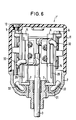
- FIGS. 6 and 7 a variant of an electrical position indicator device is shown in a representation similar to FIGS. 1 and 2, which is denoted overall by 1 'to distinguish it from the first exemplary embodiment.
- This electrical position indicator device 1 ' largely corresponds to the previously explained forms of construction of base body 2, movable element 3 and component carrier 6, which therefore need not be explained in more detail here.
- the electrical position indicator 1 'according to FIGS. 6 and 7 as switching elements 4 does not have roller switches, but proximity switches, which are assigned to the movable element 3 for detecting its position.
- These proximity switches 30 are similar to the roller switches attached to the diverging walls 15 in the preceding embodiment, which are formed by the sections 20, 21 also diverging in cross section of the component carrier 6.
- Such proximity switches 30 usually have an amplifier part 31 for signal amplification, which takes up a relatively large amount of space.
- the amplifier part 31 is integrated in a section of the connecting cable 32 which is at a distance from the proximity switch 30. Therefore, the relatively voluminous amplifier part 31 can be arranged in the space enclosed by the cup-shaped housing part 11 in such a way that the amplifier part 31 lies at a distance from the fastening point of the proximity switch 30 on the wall 15 and, for example, in the two lower corner regions in FIG. 7 comes to use this otherwise dead corner space or other free spaces around the component carrier 6.
- the base body 2 and / or the associated cup-shaped housing part for example, having a cross section other than the cross section shown, such as oval or a combination of angular and oval, or circular or combinations thereof.
- a cross section other than the cross section shown such as oval or a combination of angular and oval, or circular or combinations thereof.
- other types of switching elements 4 can also be attached, depending on the particular application.
- the terminal points 9 can also be formed by components other than the examples shown.
Claims (15)
- Equipement électrique d'affichage de position avec un corps de base (2) au milieu duquel se trouve un élément (3) de position de va-et-vient et auquel sont affectés des éléments de commande (4) pour le relèvement de position prévus sur un support de composants (6) conçu sous forme d'un composant séparé et fixable au corps de base (2), caractérisé par le fait que le support de composants (6) entoure l'élément mobile (3) et qu'il comporte un plan de symétrie (A) passant au milieu du corps de base (2) de manière à ce que pour le supports de composants (6) fixé sur le corps de base (2) les éléments de commande (4) sont aménagés à une surface latérale du corps de base (2) et les points de serrage (9) à une surface latérale opposée et que le support de composants (6) présente dans la section deux sections parallèles opposées (16, 17) qui sont orientées tangentiellement au cercle fondamental de l'élément mobile (3).
- Equipement électrique d'affichage de position selon la revendication 1, caractérisé en ce que le corps de base (2) présente une forme similairement carrée.
- Equipement électrique d'affichage de position selon la revendication 2, caractérisé en ce que le support de composants (6) est conçu de manière à ce que les parois supportant les composants (14, 15) sont dirigées plus ou moins dans le sens des coins du corps de base carré (2).
- Equipement électrique d'affichage de position selon la revendication 2 ou 3, caractérisé en ce que les parois (15) supportant les éléments de commande (4) du support de composants (6), référées au centre du corps de base (2) se dirigent de manière divergente vers les coins.
- Equipement électrique d'affichage de position selon une des revendications 2 à 4, caractérisé en ce que les parois (14) supportant les points de serrage (9) du support de composants (6), référées au centre du corps de base (2) se dirigent de manière convergente.
- Equipement électrique d'affichage de position selon une des revendications précédentes, caractérisé en ce que sur une des extrémités des sections (16, 17) se raccordent des sections en V (18, 19) pour les parois (14) supportant les endroits de serrage (9) et aux autres extrémités de manière des sections divergentes (20, 21) pour les parois (15) supportant les éléments de commande.
- Equipement électrique d'affichage de position selon une des revendications précédentes, caractérisé en ce que les platines de commande (10) sont montées pratiquement verticalement aux parois (14, 15) supportant les composants sur le support de composants (6).
- Equipement électrique d'affichage de position selon la revendication 7, caractérisé en ce que les platines de commande (10) et les parois (14) supportant les endroits de serrage opposés (9) du support de composants (6) sont aménagées de manière superposée.
- Equipement électrique d'affichage de position selon une des revendications précédentes, caractérisé en ce que le support de composants (6) est produit en une pièce et avantageusement en matière plastique.
- Equipement électrique d'affichage de position selon une des revendications précédentes, caractérisé en ce que les éléments de commande (4) relevant la position de l'élément mobile sont des interrupteurs à rouleaux (fig. 1 et 2).
- Equipement électrique d'affichage de position selon une des revendications 1 à 9, caractérisé en ce que les éléments de commande (4) relevant la position de l'élément mobile (3) sont des interrupteurs de proximité (30) (fig. 6 et 7).
- Equipement électrique d'affichage de position selon la revendication 11, caractérisé en ce que les interrupteurs de proximité (30) présentent des initiateurs de proximité et qu'une partie amplificatrice (31) est intégrée dans le câble de liaison (32) des initiateurs de proximité et ce éloignée de ce dernier.
- Equipement électrique d'affichage de position selon une des revendications précédentes, caractérisé en ce que le support de composants (6) avec les composants y montés est entouré d'une pièce de boîtier sous forme de godet (11) qui présente une section carrée correspondant au corps de base (2) et qui est fixée sur le corps de base (2).
- Equipement électrique d'affichage de position selon la revendication 13, caractérisé en ce que la pièce de boîtier sous forme de godet (11) est transparente.
- Equipement électrique d'affichage de position selon la revendication 13 ou 14, caractérisé en ce que la pièce de boîtier sous forme de godet (11) est fabriquée en matière plastique.
Applications Claiming Priority (2)
| Application Number | Priority Date | Filing Date | Title |
|---|---|---|---|
| DE3710987 | 1987-04-01 | ||
| DE19873710987 DE3710987A1 (de) | 1987-04-01 | 1987-04-01 | Elektrische stellungsanzeigevorrichtung |
Publications (3)
| Publication Number | Publication Date |
|---|---|
| EP0284941A2 EP0284941A2 (fr) | 1988-10-05 |
| EP0284941A3 EP0284941A3 (en) | 1990-05-16 |
| EP0284941B1 true EP0284941B1 (fr) | 1993-11-10 |
Family
ID=6324638
Family Applications (1)
| Application Number | Title | Priority Date | Filing Date |
|---|---|---|---|
| EP88104472A Expired - Lifetime EP0284941B1 (fr) | 1987-04-01 | 1988-03-21 | Dispositif électrique d'indication de position |
Country Status (5)
| Country | Link |
|---|---|
| US (1) | US4829148A (fr) |
| EP (1) | EP0284941B1 (fr) |
| JP (1) | JPH0820240B2 (fr) |
| BR (1) | BR8801573A (fr) |
| DE (2) | DE3710987A1 (fr) |
Families Citing this family (5)
| Publication number | Priority date | Publication date | Assignee | Title |
|---|---|---|---|---|
| US7323646B2 (en) * | 2005-04-14 | 2008-01-29 | Conntrol International, Inc. | Hand and foot switch |
| US7161100B1 (en) * | 2006-04-05 | 2007-01-09 | Chung-Hsien Hsieh | Limit switch mechanism for door opening |
| US7262377B1 (en) * | 2006-11-23 | 2007-08-28 | Hiwin Mikrosystem Corp. | Limit switch control device for an actuator |
| CN104880164A (zh) * | 2015-05-29 | 2015-09-02 | 吴中区木渎蒯斌模具加工厂 | 全气动四工位旋转检测装置 |
| CN111883393B (zh) * | 2020-07-30 | 2022-10-04 | 福建省三星电气股份有限公司 | 一种开关装置的附件组件 |
Family Cites Families (8)
| Publication number | Priority date | Publication date | Assignee | Title |
|---|---|---|---|---|
| US2639337A (en) * | 1951-01-03 | 1953-05-19 | Yale & Towne Mfg Co | Two-speed reversible controller |
| US3472977A (en) * | 1967-10-11 | 1969-10-14 | Clarence B Ziegler Jr | Linear switch actuator having radial spaced cams and switches |
| DE1763107A1 (de) * | 1968-04-04 | 1971-09-02 | Ver Baubeschlag Gretsch Co | Elektromotorische Antriebsvorrichtung fuer Oberlichtoeffner od.dgl. |
| US3703616A (en) * | 1970-03-18 | 1972-11-21 | Martin Ind Inc | Gauge actuated circuit control unit |
| DE7130884U (de) * | 1971-08-12 | 1971-11-11 | Haufe R | Kontaktschalter Aufnahme |
| US3937912A (en) * | 1974-09-30 | 1976-02-10 | Martin Industries, Inc. | Pressure responsive circuit control unit having adjustable, interchangeable actuator components and cam-operated switch |
| US4247744A (en) * | 1979-01-31 | 1981-01-27 | Birkle Paul G | Limit switch |
| DE3427498C2 (de) * | 1984-07-26 | 1986-08-07 | Ifm Electronic Gmbh, 4300 Essen | Elektronisches, vorzugsweise berührungslos arbeitendes Schaltgerät |
-
1987
- 1987-04-01 DE DE19873710987 patent/DE3710987A1/de not_active Withdrawn
-
1988
- 1988-03-18 US US07/170,148 patent/US4829148A/en not_active Expired - Lifetime
- 1988-03-21 DE DE88104472T patent/DE3885491D1/de not_active Expired - Fee Related
- 1988-03-21 EP EP88104472A patent/EP0284941B1/fr not_active Expired - Lifetime
- 1988-03-31 JP JP63081162A patent/JPH0820240B2/ja not_active Expired - Lifetime
- 1988-04-04 BR BR8801573A patent/BR8801573A/pt not_active IP Right Cessation
Also Published As
| Publication number | Publication date |
|---|---|
| JPS63261105A (ja) | 1988-10-27 |
| DE3710987A1 (de) | 1988-10-13 |
| US4829148A (en) | 1989-05-09 |
| JPH0820240B2 (ja) | 1996-03-04 |
| EP0284941A2 (fr) | 1988-10-05 |
| DE3885491D1 (de) | 1993-12-16 |
| BR8801573A (pt) | 1988-11-08 |
| EP0284941A3 (en) | 1990-05-16 |
Similar Documents
| Publication | Publication Date | Title |
|---|---|---|
| EP0925617B1 (fr) | Jonction d'un guide d'ondes sur une ligne triplaque | |
| EP0627104B1 (fr) | Dispositif de mise en contact pour une carte a puce | |
| DD253376A5 (de) | Bauelement fuer baumodelle, insbesondere bauspielzeuge | |
| DE2657783A1 (de) | Drucktastenschalter und tastensatz | |
| DE2328620B2 (de) | Mehrpolige Kontaktleiste | |
| DE3928751C2 (fr) | ||
| EP0284941B1 (fr) | Dispositif électrique d'indication de position | |
| EP0288868A2 (fr) | Dispositif de connexion électriquement conductrice de deux composants | |
| EP0909223B1 (fr) | Transducteur ultrasonique avec element de contact | |
| EP0594807B1 (fr) | Dispositif pour la mise en circuit et hors circuit d'un consommateur electrique, en particulier pour instruments de controle sur un tableau de bord d'un vehicule automobile | |
| DE3619636A1 (de) | Gehaeuse fuer integrierte schaltkreise | |
| WO1988009557A1 (fr) | Appareil electrique, en particulier commutateur electrique pour vehicules a moteur | |
| DE2652077B2 (de) | Anschluß- und Haltevorrichtung für plättchenförmige Körper | |
| DE4102349C2 (de) | Kontrollgerät zur Stromkreisüberwachung | |
| DE1640538B2 (de) | Elektrischer Wippenschalter oder Taster | |
| EP0278484A2 (fr) | Méthode de fabrication d'une plaquette utilisée pour la digitalisation | |
| EP0117456B1 (fr) | Cascade haute tension | |
| DE2736545A1 (de) | Steckeinheit mit einer elektrische bauelemente tragenden leiterplatte | |
| DE102017116381A1 (de) | Elektrisches Bauelement mit Lötverbindung | |
| DE3119397C2 (de) | Gehäuse für elektrische und/oder elektronische Bauelemente | |
| DE19621125A1 (de) | Stiftsteckerteil für ein Stecksystem in SMD-Anschlußtechnik | |
| DE19822811C1 (de) | Kontaktträger | |
| DE2350041A1 (de) | Schnappschalter und schaltvorrichtung mit wenigstens zwei schnappschaltern | |
| DE3434848A1 (de) | Verbindung zwischen einem bolzen und einer federmutter | |
| DE3515721C2 (fr) |
Legal Events
| Date | Code | Title | Description |
|---|---|---|---|
| PUAI | Public reference made under article 153(3) epc to a published international application that has entered the european phase |
Free format text: ORIGINAL CODE: 0009012 |
|
| AK | Designated contracting states |
Kind code of ref document: A2 Designated state(s): CH DE FR GB IT LI |
|
| PUAL | Search report despatched |
Free format text: ORIGINAL CODE: 0009013 |
|
| AK | Designated contracting states |
Kind code of ref document: A3 Designated state(s): CH DE FR GB IT LI |
|
| RHK1 | Main classification (correction) |
Ipc: H01H 15/14 |
|
| 17P | Request for examination filed |
Effective date: 19900626 |
|
| 17Q | First examination report despatched |
Effective date: 19920703 |
|
| GRAA | (expected) grant |
Free format text: ORIGINAL CODE: 0009210 |
|
| AK | Designated contracting states |
Kind code of ref document: B1 Designated state(s): CH DE FR GB IT LI |
|
| REF | Corresponds to: |
Ref document number: 3885491 Country of ref document: DE Date of ref document: 19931216 |
|
| ITF | It: translation for a ep patent filed |
Owner name: STUDIO JAUMANN |
|
| ET | Fr: translation filed | ||
| GBT | Gb: translation of ep patent filed (gb section 77(6)(a)/1977) |
Effective date: 19940126 |
|
| PLBE | No opposition filed within time limit |
Free format text: ORIGINAL CODE: 0009261 |
|
| STAA | Information on the status of an ep patent application or granted ep patent |
Free format text: STATUS: NO OPPOSITION FILED WITHIN TIME LIMIT |
|
| 26N | No opposition filed | ||
| REG | Reference to a national code |
Ref country code: GB Ref legal event code: IF02 |
|
| PGFP | Annual fee paid to national office [announced via postgrant information from national office to epo] |
Ref country code: DE Payment date: 20060324 Year of fee payment: 19 |
|
| PGFP | Annual fee paid to national office [announced via postgrant information from national office to epo] |
Ref country code: FR Payment date: 20060328 Year of fee payment: 19 |
|
| PGFP | Annual fee paid to national office [announced via postgrant information from national office to epo] |
Ref country code: IT Payment date: 20060331 Year of fee payment: 19 |
|
| PGFP | Annual fee paid to national office [announced via postgrant information from national office to epo] |
Ref country code: CH Payment date: 20060425 Year of fee payment: 19 |
|
| PGFP | Annual fee paid to national office [announced via postgrant information from national office to epo] |
Ref country code: GB Payment date: 20060426 Year of fee payment: 19 |
|
| REG | Reference to a national code |
Ref country code: CH Ref legal event code: PL |
|
| GBPC | Gb: european patent ceased through non-payment of renewal fee |
Effective date: 20070321 |
|
| REG | Reference to a national code |
Ref country code: FR Ref legal event code: ST Effective date: 20071130 |
|
| PG25 | Lapsed in a contracting state [announced via postgrant information from national office to epo] |
Ref country code: DE Free format text: LAPSE BECAUSE OF NON-PAYMENT OF DUE FEES Effective date: 20071002 |
|
| PG25 | Lapsed in a contracting state [announced via postgrant information from national office to epo] |
Ref country code: LI Free format text: LAPSE BECAUSE OF NON-PAYMENT OF DUE FEES Effective date: 20070331 Ref country code: CH Free format text: LAPSE BECAUSE OF NON-PAYMENT OF DUE FEES Effective date: 20070331 |
|
| PG25 | Lapsed in a contracting state [announced via postgrant information from national office to epo] |
Ref country code: GB Free format text: LAPSE BECAUSE OF NON-PAYMENT OF DUE FEES Effective date: 20070321 |
|
| PG25 | Lapsed in a contracting state [announced via postgrant information from national office to epo] |
Ref country code: FR Free format text: LAPSE BECAUSE OF NON-PAYMENT OF DUE FEES Effective date: 20070402 |
|
| PG25 | Lapsed in a contracting state [announced via postgrant information from national office to epo] |
Ref country code: IT Free format text: LAPSE BECAUSE OF NON-PAYMENT OF DUE FEES Effective date: 20070321 |