EP0284535A1 - Bicycle of which the wheels are supported at one side only by the frame - Google Patents
Bicycle of which the wheels are supported at one side only by the frame Download PDFInfo
- Publication number
- EP0284535A1 EP0284535A1 EP88470003A EP88470003A EP0284535A1 EP 0284535 A1 EP0284535 A1 EP 0284535A1 EP 88470003 A EP88470003 A EP 88470003A EP 88470003 A EP88470003 A EP 88470003A EP 0284535 A1 EP0284535 A1 EP 0284535A1
- Authority
- EP
- European Patent Office
- Prior art keywords
- frame
- bicycle
- brake
- wheel
- fixed
- Prior art date
- Legal status (The legal status is an assumption and is not a legal conclusion. Google has not performed a legal analysis and makes no representation as to the accuracy of the status listed.)
- Granted
Links
Images


Classifications
-
- B—PERFORMING OPERATIONS; TRANSPORTING
- B62—LAND VEHICLES FOR TRAVELLING OTHERWISE THAN ON RAILS
- B62K—CYCLES; CYCLE FRAMES; CYCLE STEERING DEVICES; RIDER-OPERATED TERMINAL CONTROLS SPECIALLY ADAPTED FOR CYCLES; CYCLE AXLE SUSPENSIONS; CYCLE SIDE-CARS, FORECARS, OR THE LIKE
- B62K21/00—Steering devices
- B62K21/02—Front wheel forks or equivalent, e.g. single tine
-
- B—PERFORMING OPERATIONS; TRANSPORTING
- B62—LAND VEHICLES FOR TRAVELLING OTHERWISE THAN ON RAILS
- B62K—CYCLES; CYCLE FRAMES; CYCLE STEERING DEVICES; RIDER-OPERATED TERMINAL CONTROLS SPECIALLY ADAPTED FOR CYCLES; CYCLE AXLE SUSPENSIONS; CYCLE SIDE-CARS, FORECARS, OR THE LIKE
- B62K25/00—Axle suspensions
- B62K25/005—Axle suspensions characterised by the axle being supported at one end only
-
- B—PERFORMING OPERATIONS; TRANSPORTING
- B62—LAND VEHICLES FOR TRAVELLING OTHERWISE THAN ON RAILS
- B62K—CYCLES; CYCLE FRAMES; CYCLE STEERING DEVICES; RIDER-OPERATED TERMINAL CONTROLS SPECIALLY ADAPTED FOR CYCLES; CYCLE AXLE SUSPENSIONS; CYCLE SIDE-CARS, FORECARS, OR THE LIKE
- B62K25/00—Axle suspensions
- B62K25/02—Axle suspensions for mounting axles rigidly on cycle frame or fork, e.g. adjustably
-
- B—PERFORMING OPERATIONS; TRANSPORTING
- B62—LAND VEHICLES FOR TRAVELLING OTHERWISE THAN ON RAILS
- B62K—CYCLES; CYCLE FRAMES; CYCLE STEERING DEVICES; RIDER-OPERATED TERMINAL CONTROLS SPECIALLY ADAPTED FOR CYCLES; CYCLE AXLE SUSPENSIONS; CYCLE SIDE-CARS, FORECARS, OR THE LIKE
- B62K3/00—Bicycles
- B62K3/02—Frames
Definitions
- the present invention relates to a bicycle of which one or both wheels are fixed in cantilever on the elements which constitute the frame of the bicycle.
- the fixing of the wheels on the frame of a bicycle is traditionally carried out by means of a front fork which oscillates on the frame and a rear fork which forms an integral part of the frame.
- a bicycle wheel rotates around an axis and this axis is fixed by its two ends to the front fork arms for the front wheel and to the seat stays and frame bases which constitute the rear fork.
- a bicycle frame is therefore symmetrical with regard to the fixing of wheels.
- the device according to the invention overcomes these drawbacks.
- this result is obtained with a bicycle of the above type, characterized in that the rear part of the frame is formed by an arm which links the rear wheel to the frame, the arm (1) being fixed on the bottom bracket of the frame by welding or brazing, its shape being such that it allows the passage of the rear wheel and the chain, said arm receiving at its end a socket (2) welded or brazed in which is housed a bearing (3).
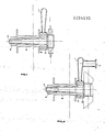
- the device comprises a single arm which links the rear wheel to the frame according to FIG. 1.
- This arm 1 is fixed to the bottom bracket of the frame by welding or brazing. Its shape is such that it allows the passage of the rear wheel and the chain.
- This arm receives at its end a socket 2 welded or brazed in which is housed a bearing 3.
- This bearing is stopped in translation in its housing by a shoulder and by bonding or then by a shoulder and crimping or by a shoulder and an elastic ring or rod.
- This bearing is crossed by an axis 4 which receives a free wheel at its end.
- On the left side of this axis is fixed the means 5 which supports the wheel which can be of all types known up to now. The whole is fixed together by a nut 6 to one or more threads whose direction of pitch is such that the tensile force automatically ensures the tightening of the nut.
- the freewheel may comprise several pinions according to FIG. 2.
- the bicycle is then equipped with a gear change mechanism fixed at 7.
- the chain can be wrapped by a waterproof or non-waterproof casing which remains in position when the rear wheel is removed.
- one solution is to oscillate a conventional rim brake around an axis.
- the amplitude of the oscillation must be sufficient to allow easy removal of the rear wheel.
- the rear wheel On a bicycle equipped with this device, the rear wheel is extracted first by rocking the brake, then it is sufficient to remove the fixing nut from the rear wheel. So he is easy to remove the rear wheel because the chain, the gear change mechanism if it exists and the chain case if it exists remain in place on the bicycle.
- refitting the rear wheel on the bicycle simply place it on its axle, screw the fixing nut until it is in contact with the rear wheel hub and tilt the rear brake to return it to the operating position.
- a variant of the brake system on the rear wheel consists in using a drum brake in the rear hub according to FIG. 4.
- the flange 9 is stopped in rotation by an anchoring lug linked to the arm which supports the wheels.
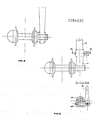
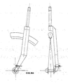
- the device according to the invention comprises a steering system the connection of which between the front wheel and the frame is effected by means of a support arm connected to the steering pivot tube which oscillates inside the frame socket in accordance with known solutions used in bicycle technology.
- the removal of the front wheel is done according to the solutions proposed either by unscrewing the front wheel axle relative to the support arm, or by acting on the conical pin in Figure 6 and pulling the front wheel down.
- the front wheel is refitted without major difficulties in the opposite direction to the removal operations.
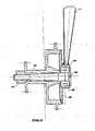
- the device comprises, according to FIG. 7, socket 10 welded or brazed to the support arm 11 in which a bearing 12 is housed.
- This bearing is stopped in translation in its housing by a shoulder and by bonding or else by a shoulder and crimping or else by a shoulder and an elastic ring or rod.
- This bearing is crossed by an axis 13 shouldered at its end, on this axis is fixed the hub 14 in which the brake drum is located.
- a flange 15 which supports the brake linings and the brake control mechanism is fitted inside the drum and is centered on the sleeve.
- the flange 15 is stopped in rotation by an anchoring lug linked to the arm which supports the wheel.
- the whole is assembled by a nut 16 with one or more threads. When removing, simply unscrew the nut to remove the front wheel instantly.
- the brake flange, the brake control mechanism and the anchoring of the brake on the front wheel support remain in position and are not manipulated either when removing or installing the wheel. before.
- the front wheel is installed in the reverse direction to the removal operation. Note that the nut must be permanently tightened when reassembling the front wheel on the frame.
- the steering device according to the invention can be located either to the right or to the left of the front wheel, the important thing being to ensure good alignment of the front wheel and the axis of longitudinal symmetry from the bicycle.
- the fixing nut is mounted on the wheel hub so that it always performs its tightening function and that in addition it is always linked to its hub in the event of removal of the wheel, so as to obtain a "captive" nut.
- a variant of the device according to the invention makes it possible to use, when the brakes are with drums in the hub, identical wheels for the front and for the rear of the bicycle, therefore to manufacture a single type of wheel for a bicycle.
- the device according to the invention can be applied to all types and all sizes of bicycles, whether they are intended for adults, children, competition, hiking, etc.
- a bicycle equipped with the device according to the invention can also receive all types of accessories known and used in bicycle technology.
- FIG. 5 represents an example of attachment of the front wheel to the steering system according to the device according to the invention.
- the tightening of the axle of the front wheel on the steering system can be obtained according to FIG. 5 for example by using a screwdriver which is introduced into the slot at the end of the axle of the front wheel.
- the tightening of the axis of the front wheel on the steering system can be obtained by other means than the screwdriver without departing from the spirit of the invention. It suffices to modify the end of the axle of the front wheel according to the chosen clamping means.
- Figure 6 shows another example of fixing the front wheel to the steering system according to the device according to the invention.
- the part 17 which can be welded to the wheel axle or be an integral part of the wheel axle when its end is bent at about 90 ° comes to fit inside the steering tube 18 via of the part 19.
- the part 17 has at its end a flat on which the conical pin 20 is supported.
- This pin 20 passes through the part 19 right through, it has a thread at one end and the operating member at the other pivoting 21. To remove the wheel, it suffices for example to slightly unscrew the pin 20 using the operating member 21 and to pull the whole of the wheel down. The wheel refitting operation is carried out in the opposite direction to the removal operation.
- FIG. 12 represents a variant of the rear part of a bicycle equipped according to the invention with a drum brake in the hub or not, with a chain case or not, with a mechanism for changing the speeds or not, ...
- a tube 22 which stiffens the rear part of the frame and limits deformation of the wheel support arm.
- the support consists of two fixing lugs 23 fixed at one end to the seat tube of the frame, at the other end are fixed two sockets 24. These sockets 24 are traversed for example by a screw 25 to the at the end of this screw is a shoulder on which nut 26 rests. This screw provides the connection between the lateral sockets and the central socket 27.
- connection between the socket 27 and the sockets 24 is such that it ensures a rotation of angle ⁇ and of axis x ⁇ x of the socket 27 and of the screw 25 relative to the frame.
- the rear rim brake is fixed on this mechanism thanks to the pin 28 which crosses both parts 27 and 25.
- FIG. 15 represents according to the invention an example of "captive" nut for fixing bicycle wheels in accordance with FIGS. 1, 2, 3, 4, 7, 9B, 11, 12, 13.
- a nut 29 provided a shoulder 30 fixes the wheel on the bicycle. This nut is constantly linked to the wheel hub, even in the event of removal via the flange 31.
Abstract
Description
La présente invention concerne une bicyclette dont une roue ou les deux sont fixées en porte à faux sur les éléments qui constituent le cadre de la bicyclette.The present invention relates to a bicycle of which one or both wheels are fixed in cantilever on the elements which constitute the frame of the bicycle.
La fixation des roues sur le cadre d'une bicyclette est traditionnellement réalisée par l'intermédiaire d'une fourche avant qui oscille sur le cadre et d'une fourche arrière qui fait partie intégrante du cadre.The fixing of the wheels on the frame of a bicycle is traditionally carried out by means of a front fork which oscillates on the frame and a rear fork which forms an integral part of the frame.
Traditionnellement, une roue de bicyclette tourne autour d'un axe et cet axe est fixé par ses deux extrémités aux bras de fourche avant pour la roue avant et aux haubans et bases du cadre qui constituent la fourche arrière. Un cadre de bicyclette est donc symétrique en ce qui concerne la fixation de roues.Traditionally, a bicycle wheel rotates around an axis and this axis is fixed by its two ends to the front fork arms for the front wheel and to the seat stays and frame bases which constitute the rear fork. A bicycle frame is therefore symmetrical with regard to the fixing of wheels.
Mis à part quelques procédés techniques compliqués, tel que par exemple le brevet US 4 170 369, il est impossible de déposer la roue arrière en laissant en place la chaîne de transmission de la bicyclette. Il faut donc, à chaque démontage, manipuler celle-ci au risque de la dérégler, de dérégler le dérailleur et de fausser le centrage de la roue arrière ce qui entraîne un mauvais fonctionnement du frein arrière surtout lorsque celui-ci est un frein sur jante.Aside from a few complicated technical processes, such as, for example, US Pat. No. 4,170,369, it is impossible to remove the rear wheel while leaving the transmission chain of the bicycle in place. It is therefore necessary, at each disassembly, to handle it at the risk of disturbing it, disrupting the derailleur and distorting the centering of the rear wheel, which leads to a malfunction of the rear brake, especially when it is a rim brake. .
De plus, lorsque la bicyclette est équipée de freins à tambour dans les moyeux avant et arrière il faut, pour déposer une roue, démonter le système d'ancrage du flasque de frein et aussi dans certains cas la partie arrière du câble de frein.In addition, when the bicycle is fitted with drum brakes in the front and rear hubs, to remove a wheel, dismantle the anchoring system of the brake flange and also in some cases the rear part of the brake cable.
Le dispositif selon l'invention permet de remédier à ces inconvénients.The device according to the invention overcomes these drawbacks.
Conformément à l'invention, ce résultat est obtenu avec une bicyclette du type ci-dessus, caractérisée en ce que la partie arrière du cadre est formée d'un bras qui lie la roue arrière au cadre, le bras (1) étant fixé sur le boîtier de pédalier du cadre par soudage ou brasage, sa forme étant telle qu'elle permette le passage de la roue arrière et de la chaîne, ledit bras recevant à son extrémité une douille (2) soudée ou brasée dans laquelle vient se loger un roulement (3).According to the invention, this result is obtained with a bicycle of the above type, characterized in that the rear part of the frame is formed by an arm which links the rear wheel to the frame, the arm (1) being fixed on the bottom bracket of the frame by welding or brazing, its shape being such that it allows the passage of the rear wheel and the chain, said arm receiving at its end a socket (2) welded or brazed in which is housed a bearing (3).
D'autres caractéristiques de mise en oeuvre de l'invention apparaîtront dans la description faite ci-après d'un certain nombre de modes de mise en oeuvre de l'invention, en référence aux dessins annexés dans lesquels :
- - la figure 1 représente en coupe un exemple de la partie arrière d'une bicyclette équipée du dispositif selon l'invention ;
- - la figure 2 équipée d'une variante du dispositif selon l'invention ;
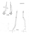
- - la figure 3 représente l'arrière d'une bicyclette équipée du dispositif selon l'invention et plus précisément un exemple de support oscillant de frein sur jante selon l'invention (il donne un exemple de l'amplitude du mouvement de l'axe support de frein) ;
- - la figure 4 représente en coupe un exemple de la partie arrière d'une bicyclette équipée d'un frein à tambour dans le moyeu conformément au dispositif selon l'invention ;
- - la figure 5 représente un exemple de fixation de la roue avant au système de direction conforme au dispositif selon l'invention ;
- - la figure 6 représente un autre exemple de fixation de la roue avant au système de direction conforme au dispositif selon l'invention ;
- - la figure 7 représente en coupe un exemple de la partie avant de la bicyclette équipée d'un frein à tambour dans le moyeu conformément au dispositif selon l'invention ;
- - les figures 8, 9A et 9B représentent des exemples de réalisation selon l'invention de parties avant de bicyclettes ;
- - la figure 10 représente un exemple de partie supérieure de direction de bicyclette adaptable à toutes les variantes de direction conformes à l'invention, présentant la particularité d'être essentiellement formé d'un seul tube cintré de manière à assurer sa fonction selon l'invention ;
- - la figure 11 représente un exemple de partie arrière de bicyclette équipée selon l'invention d'un frein à tambour dans le moyeu ;
- - la figure 12 représente une variante de la partie arrière d'une bicyclette équipée selon l'invention d'un frein à tambour dans le moyeu ou pas, d'un carter de chaine ou pas, d'un mécanisme de changement de vitesses ou pas ;
- - la figure 13 est une variante de la figure 12 ;
- - la figure 14 est un détail de la figure 3, elle représente en voupe A-A et en section B-B un exemple selon l'invention de support de frein arrière oscillant ;
- - la figure 15 représente selon l'invention un exemple d'écrou "imperdable" pour la fixation de roues de bicyclettes conformes aux figures 1, 2, 3, 4, 7, 9B, 11, 12, 13.
- - Figure 1 shows in section an example of the rear part of a bicycle equipped with the device according to the invention;
- - Figure 2 equipped with a variant of the device according to the invention;
- - Figure 3 shows the rear of a bicycle equipped with the device according to the invention and more specifically an example of an oscillating rim brake support according to the invention (it gives an example of the amplitude of the movement of the axis brake support);
- - Figure 4 shows in section an example of the rear part of a bicycle equipped with a drum brake in the hub according to the device according to the invention;
- - Figure 5 shows an example of fixing the front wheel to the steering system according to the device according to the invention;
- - Figure 6 shows another example of fixing the front wheel to the steering system according to the device according to the invention;
- - Figure 7 shows in section an example of the front part of the bicycle equipped with a drum brake in the hub according to the device according to the invention;
- - Figures 8, 9A and 9B show embodiments according to the invention of front parts of bicycles;
- - Figure 10 shows an example of upper part of bicycle steering adaptable to all variants of steering according to the invention, having the distinction of being essentially formed of a single bent tube so as to ensure its function according to invention;
- - Figure 11 shows an example of a rear part of a bicycle equipped according to the invention with a drum brake in the hub;
- - Figure 12 shows a variant of the rear part of a bicycle fitted according to the invention with a drum brake in the hub or not, with a chain case or not, with a gear change mechanism or not ;
- - Figure 13 is a variant of Figure 12;
- - Figure 14 is a detail of Figure 3, it represents in AA and in section BB an example according to the invention of an oscillating rear brake support;
- - Figure 15 shows according to the invention an example of "captive" nut for fixing bicycle wheels according to Figures 1, 2, 3, 4, 7, 9B, 11, 12, 13.
En ce qui concerne la roue arrière, le dispositif comporte un seul bras qui lie la roue arrière au cadre selon la figure 1. Ce bras 1 est fixé sur le boîtier de pédalier du cadre par soudage ou brasage. Sa forme est telle qu'elle permet le passage de la roue arrière et de la chaîne. Ce bras reçoit à son extrémité une douille 2 soudée ou brasée dans laquelle vient se loger un roulement 3.As regards the rear wheel, the device comprises a single arm which links the rear wheel to the frame according to FIG. 1. This arm 1 is fixed to the bottom bracket of the frame by welding or brazing. Its shape is such that it allows the passage of the rear wheel and the chain. This arm receives at its end a
Ce roulement est arrêté en translation dans son logement par un épaulement et par collage ou alors par un épaulement et sertissage ou encore par un épaulemtn et un anneau ou jonc élastique. Ce roulement est traversé par un axe 4 qui reçoit à son extrémité une roue libre. Sur la partie gauche de cet axe vient se fixer le moyen 5 qui supporte la roue qui peut être de tous les types connus jusqu'à présent. Le tout est fixé ensembler par un écrou 6 à un ou plusieurs filets dont le sens du pas est tel que l'effort de traction assure automatiquement le serrage de l'écrou.This bearing is stopped in translation in its housing by a shoulder and by bonding or then by a shoulder and crimping or by a shoulder and an elastic ring or rod. This bearing is crossed by an axis 4 which receives a free wheel at its end. On the left side of this axis is fixed the means 5 which supports the wheel which can be of all types known up to now. The whole is fixed together by a nut 6 to one or more threads whose direction of pitch is such that the tensile force automatically ensures the tightening of the nut.
Selon une variante la roue libre peut comporter plusieurs pignons selon la figure 2. La bicyclette est alors équipée d'un mécanisme de changement de vitesses fixé en 7.According to a variant, the freewheel may comprise several pinions according to FIG. 2. The bicycle is then equipped with a gear change mechanism fixed at 7.
Selon une variante la chaîne peut être enveloppée par un carter étanche ou non qui reste en position lors du démontage de la roue arrière.According to a variant, the chain can be wrapped by a waterproof or non-waterproof casing which remains in position when the rear wheel is removed.
Si la bicyclette est équipée d'un frein arrière classique sur jante, il faut prévoir un mécanisme qui permet au frein de s'effacer lors de la dépose de la roue arrière. Selon la figure 3, une solution est de faire osciller un frein classique sur jante autour d'un axe.If the bicycle is fitted with a conventional rear brake on a rim, a mechanism must be provided which allows the brake to clear when the rear wheel is removed. According to Figure 3, one solution is to oscillate a conventional rim brake around an axis.
L'amplitude de l'oscillation doit être suffisante pour permettre une dépose facile de la roue arrière.The amplitude of the oscillation must be sufficient to allow easy removal of the rear wheel.
Sur une bicyclette équipée de ce dispositif, l'extraction de la roue arrière se fait tout d'abord en basculant le frein, il suffit ensuite de démonter l'écrou de fixation de la roue arrière. Il est alors aisé de déposer la roue arrière car la chaîne, le mécanisme de changement de vitesses s'il existe et le carter de chaîne s'il existe restent en place sur la bicyclette. Lors de la repose de la roue arrière sur la bicyclette, il suffit de placer celle-ci sur son axe, de visser l'écrou de fixation jusqu'à ce qu'il soit en contact avec le moyeu de la roue arrière et de basculer le frein arrière pour le remettre en position d'utilisation.On a bicycle equipped with this device, the rear wheel is extracted first by rocking the brake, then it is sufficient to remove the fixing nut from the rear wheel. So he is easy to remove the rear wheel because the chain, the gear change mechanism if it exists and the chain case if it exists remain in place on the bicycle. When refitting the rear wheel on the bicycle, simply place it on its axle, screw the fixing nut until it is in contact with the rear wheel hub and tilt the rear brake to return it to the operating position.
Une variante du système de frein sur la roue arrière consiste à utiliser un frein à tambour dans le moyeu arrière selon la figure 4.A variant of the brake system on the rear wheel consists in using a drum brake in the rear hub according to FIG. 4.
On retrouve un axe, un roulement, une douille soudée ou brasée du cadre. La différence se trouve dans la pièce no 5 qui est le moyeu de la roue arrière. Sur ce moyeu se trouve le tambour de frein 8. Un flasque 9 qui supporte les garnitures de frein et le mécanisme de commande du frein vient s'encastrer à l'entrée du tambour et se centrer sur la douille 2.We find an axis, a bearing, a welded or brazed socket of the frame. The difference lies in the part No. 5, which is the hub of the rear wheel. On this hub is the brake drum 8. A flange 9 which supports the brake linings and the brake control mechanism is fitted at the inlet of the drum and is centered on the
Le flasque 9 est arrêté en rotation par une patte d'ancrage liée au bras qui supporte les roues.The flange 9 is stopped in rotation by an anchoring lug linked to the arm which supports the wheels.
Lors de la dépose de la roue, la chaîne, le carter de chaine s'il existe, le flasque du frein à tambour, son mécanisme de commande et le système de changement de vitesses s'il existe, restent sur la bicyclette. Pour extraire la roue arrière, il suffit de dévisser l'écrou.When removing the wheel, the chain, the chain case if there is one, the flange of the drum brake, its control mechanism and the gear change system if there is any, remain on the bicycle. To remove the rear wheel, simply unscrew the nut.
Lors de la repose de la roue arrière, il suffit de mettre en place celle-ci sur son axe sans précautions particulières et de visser à la main l'écrou de fixation de la roue arrière. Le couple de serrage définitif sera obtenu dès les premiers tours de roue, le sens du filetage sur l'axe est tel que l'effort de traction assure automatiquement le serrage de l'écrou.When refitting the rear wheel, it suffices to install it on its axle without special precautions and to screw the rear wheel fixing nut by hand. The final tightening torque will be obtained from the first wheel turns, the direction of the thread on the axle is such that the tensile force automatically ensures the tightening of the nut.
En ce qui concerne la roue avant, le dispositif selon l'invention comporte un système de direction dont la liaison entre la roue avant et le cadre s'effectue grâce à un bras support relié au tube pivot de direction qui oscille à l'intérieur de la douille du cadre conformément aux solutions connues et utilisées dans la technologie de la bicyclette.As regards the front wheel, the device according to the invention comprises a steering system the connection of which between the front wheel and the frame is effected by means of a support arm connected to the steering pivot tube which oscillates inside the frame socket in accordance with known solutions used in bicycle technology.
La liaison entre ce bras support et la roue avant qui peut être de tous types connus jusqu'à présent, se fait dans le cas où le frein avant est sur jante, par un filetage entre la partie inférieure du bras support et l'extrémité de l'axe de la roue avant, la figure 5 représente une solution possible ou encore par un emboîtement à la base du bras support la figure 6 représente une solution possible. Si l'axe de la roue avant est fixé par filetage ou par emboîtement à la base du bras support de direction, alors cet axe est fixe en rotation par rapport au cadre. La roue avant et son moyeu tournent alors autour de cet axe par l'intermédiaire de roulement annulaires ou d'un système à billes, cônes et cuvettes qui sont des types de roulements connus et utilisés dans la technologie de la bicyclette. La dépose de la roue avant se fait suivant les solutions proposées soit en dévissant l'axe de roue avant par rapport au bras support, soit en agissant sur la goupille conique figure 6 et un tirant la roue avant vers le bas. La repose de la roue avant s'effectue sans difficultés majeurs dans le sens inverse des opérations de dépose.The connection between this support arm and the front wheel, which can be of any type known up to now, is made in the case where the front brake is on the rim, by a thread between the lower part of the support arm and the end of the axis of the front wheel, Figure 5 shows a possible solution or even by an interlocking at the base of the support arm Figure 6 shows a possible solution. If the axis of the front wheel is fixed by thread or by interlocking at the base of the steering support arm, then this axis is fixed in rotation relative to the frame. The front wheel and its hub then rotate around this axis via annular bearings or a system of balls, cones and cups which are known types of bearings and used in bicycle technology. The removal of the front wheel is done according to the solutions proposed either by unscrewing the front wheel axle relative to the support arm, or by acting on the conical pin in Figure 6 and pulling the front wheel down. The front wheel is refitted without major difficulties in the opposite direction to the removal operations.
Dans le cas où le frein avant est à tambour dans le moyeu, le dispositif comporte selon la figure 7 douille 10 soudée ou brasée au bras support 11 dans laquelle vient se loger un roulement 12. Ce roulement est arrêté en translation dans son logement par un épaulement et par collage ou alors par un épaulement et sertissage ou encore par un épaulement et un anneau ou jonc élastique.In the case where the front brake is a drum in the hub, the device comprises, according to FIG. 7,
Ce roulement est traversé par un axe 13 épaulé à son extrémité, sur cet axe vient se fixer le moyeu 14 dans lequel se trouve le tambour de frein. Un flasque 15 qui supporte les garnitures de frein et le mécanisme de commande du frein vient s'encastrer à l'intérieur du tambour et se centrer sur la douille. Le flasque 15 est arrêté en rotation par une patte d'ancrage liée au bras qui supporte la roue. Le tout est assemblé par un écrou 16 à un ou plusieurs filets. Lors de la dépose, il suffit de dévisser l'écrou pour extraire la roue avant instantanément. Le flasque de frein, le mécanisme de commande du frein et l'ancrage du frein sur le support de la roue avant restent en position et ne font l'objet d'aucune manipulation aussi bien à la dépose qu'à la repose de la roue avant. La repose de la roue avant s'effectue dans le sens inverse de l'opération de dépose. Il est à remarquer que l'écrou doit être serré définitivement lors du remontage de la roue avant sur le cadre.This bearing is crossed by an axis 13 shouldered at its end, on this axis is fixed the
Il est également à remarquer que le dispositif de direction selon l'invention peut se trouver indifféremment à droite ou à gauche de la roue avant, l'important étant d'assurer un bon alignement de la roue avant et de l'axe de symétrie longitudinale de la bicyclette.It should also be noted that the steering device according to the invention can be located either to the right or to the left of the front wheel, the important thing being to ensure good alignment of the front wheel and the axis of longitudinal symmetry from the bicycle.
Selon une variante du dispositif de liaison entre la roue arrière, la roue avant et leur axe respectif de liaison sur la bicyclette, l'écrou de fixation est monté sur le moyeu des roues de manières à ce qu'il assure toujours sa fonction de serrage et qu'en plus il soit toujours lié à son moyeu en cas de dépose de la roue, de manière à obtenir un écrou "imperdable".According to a variant of the connection device between the rear wheel, the front wheel and their respective axis of connection on the bicycle, the fixing nut is mounted on the wheel hub so that it always performs its tightening function and that in addition it is always linked to its hub in the event of removal of the wheel, so as to obtain a "captive" nut.
Une variante du dispositif selon l'invention permet d'utiliser lorsque les freins sont à tambour dans le moyeu, des roues identiques pour l'avant et pour l'arrière de la bicyclette donc de fabriquer un seul type de roue pour une bicyclette.A variant of the device according to the invention makes it possible to use, when the brakes are with drums in the hub, identical wheels for the front and for the rear of the bicycle, therefore to manufacture a single type of wheel for a bicycle.
Le dispositif selon l'invention peut s'appliquer à tous les types et à toutes les tailles de bicyclettes qu'elles soient destinées aux adultes, aux enfants, à la compétition, à la randonnée...The device according to the invention can be applied to all types and all sizes of bicycles, whether they are intended for adults, children, competition, hiking, etc.
Une bicyclette équipée du dispositif selon l'invention peut également recevoir tous les types d'accessoires connus et utilisés dans la technologie de la bicyclette.A bicycle equipped with the device according to the invention can also receive all types of accessories known and used in bicycle technology.
On notera également dans les dessins un certain nombre de caractéristiques spécifiques.A number of specific features will also be noted in the drawings.
Ainsi la figure 5 représente un exemple de fixation de la roue avant au système de direction conforme au dispositif selon l'invention. Le serrage de l'axe de la roue avant sur le système de direction peut être obtenu selon la figure 5 par exemple en utilisant un tournevis que l'on introduit dans la fente à l'extrémité de l'axe de la roue avant. Le serrage de l'axe de la roue avant sur le système de direction peut être obtenu par d'autres moyens que le tournevis sans s'écarter pour autant de l'esprit de l'invention. Il suffit de modifier l'extrémité de l'axe de la roue avant en fonction du moyen de serrage choisi.Thus, FIG. 5 represents an example of attachment of the front wheel to the steering system according to the device according to the invention. The tightening of the axle of the front wheel on the steering system can be obtained according to FIG. 5 for example by using a screwdriver which is introduced into the slot at the end of the axle of the front wheel. The tightening of the axis of the front wheel on the steering system can be obtained by other means than the screwdriver without departing from the spirit of the invention. It suffices to modify the end of the axle of the front wheel according to the chosen clamping means.
De même la figure 6 représente un autre exemple de fixation de la roue avant au système de direction conforme au dispositif selon l'invention. La pièce 17 qui peut être soudée sur l'axe de la roue ou faire partie intégrante de l'axe de roue quand son extrémité est coudée à environ 90° vient s'emboîter à l'intérieur du tube de direction 18 par l'intermédiaire de la pièce 19. La pièce 17 comporte à son extrémité un méplat sur lequel vient s'appuyer la goupille conique 20.Similarly, Figure 6 shows another example of fixing the front wheel to the steering system according to the device according to the invention. The
Cette goupille 20 traverse la pièce 19 de part en part, elle possède à une extrémité un filetage et à l'autre l'organe de manoeuvre pivotant 21. Pour déposer la roue, il suffit par exemple de dévisser légèrement la goupille 20 à l'aide de l'organe de manoeuvre 21 et de tirer l'ensemble de la roue vers le bas. L'opération de repose de la roue se fait dans le sens inverse de l'opération de dépose.This
Par ailleurs, la figure 12 représente une variante de la partie arrière d'une bicyclette équipée selon l'invention d'un frein à tambour dans le moyeu ou pas, d'un carter de chaine ou pas, d'une mécanisme de changement de vitesses ou pas,... Quel que soit le type de bicyclette équipée selon l'invention, il est possible par exemple selon la figure 12 de rajouter entre le bras support de roue et le tube de selle du cadre un tube 22 qui rigidifie la partie arrière du cadre et limite les déformations du bras support de roue.Furthermore, FIG. 12 represents a variant of the rear part of a bicycle equipped according to the invention with a drum brake in the hub or not, with a chain case or not, with a mechanism for changing the speeds or not, ... Whatever type of bicycle equipped according to the invention, it is possible for example according to FIG. 12 to add between the wheel support arm and the seat tube of the frame a
A la figure 14 le support est constitué de deux pattes de fixation 23 fixées par une extrémité sur le tube de selle du cadre, à l'autre extrémité sont fixées deux douilles 24. Ces douilles 24 sont traversées par exemple par une vis 25 à l'extrémité de cette vis se trouve un épaulement sur lequel vient s'appuyer en écrou 26. Cette vis assure la liaison entre les douilles latérales et la douille centrale 27.In FIG. 14, the support consists of two fixing lugs 23 fixed at one end to the seat tube of the frame, at the other end are fixed two
La liaison entre la douille 27 et les douilles 24 est telle qu'elle assure une rotation d'angle γ et d'axe xʹx de la douille 27 et de la vis 25 par rapport au cadre. Le frein arrière sur jante vient se fixer sur ce mécanisme grâce à l'axe 28 qui traverse à la fois les pièces 27 et 25.The connection between the socket 27 and the
Enfin, la figure 15 représente selon l'invention un exemple d'écrou "imperdable" pour la fixation de roues de bicyclettes conformes aux figures 1, 2, 3, 4, 7, 9B, 11, 12, 13. Un écrou 29 muni d'un épaulement 30 fixe la roue sur la bicyclette. Cet écrou est constamment lié au moyeu de la roue, même en cas de dépose par l'intermédiaire du flasque 31.Finally, FIG. 15 represents according to the invention an example of "captive" nut for fixing bicycle wheels in accordance with FIGS. 1, 2, 3, 4, 7, 9B, 11, 12, 13. A
Claims (6)
Applications Claiming Priority (2)
| Application Number | Priority Date | Filing Date | Title |
|---|---|---|---|
| FR8702456 | 1987-02-23 | ||
| FR8702456A FR2611641B1 (en) | 1987-02-23 | 1987-02-23 | BICYCLE WHOSE WHEELS ARE FIXED OVERALL ON THE FRAME |
Publications (2)
| Publication Number | Publication Date |
|---|---|
| EP0284535A1 true EP0284535A1 (en) | 1988-09-28 |
| EP0284535B1 EP0284535B1 (en) | 1992-04-29 |
Family
ID=9348274
Family Applications (1)
| Application Number | Title | Priority Date | Filing Date |
|---|---|---|---|
| EP88470003A Expired - Lifetime EP0284535B1 (en) | 1987-02-23 | 1988-02-23 | Bicycle of which the wheels are supported at one side only by the frame |
Country Status (4)
| Country | Link |
|---|---|
| EP (1) | EP0284535B1 (en) |
| DE (1) | DE3870500D1 (en) |
| ES (1) | ES2032999T3 (en) |
| FR (1) | FR2611641B1 (en) |
Cited By (6)
| Publication number | Priority date | Publication date | Assignee | Title |
|---|---|---|---|---|
| EP0612629A2 (en) * | 1993-02-23 | 1994-08-31 | Antonio Guerra Navas | Hub for bicycle wheels |
| EP1990265A1 (en) * | 2007-05-05 | 2008-11-12 | Liteville GmbH | Shaft system for attaching a wheel |
| US7793960B2 (en) * | 2008-04-01 | 2010-09-14 | Aleksandr Sherman | Bicycle wheel mounting assembly |
| WO2012108788A2 (en) * | 2011-02-08 | 2012-08-16 | Petrovsky Jury Antonovich | Racing bicycle |
| WO2013041093A1 (en) * | 2011-09-23 | 2013-03-28 | Bettin Karsten | Frame for bicycles |
| ITPD20120388A1 (en) * | 2012-12-19 | 2014-06-20 | Diego Pizzato | METHOD OF BALANCING A BICYCLE AND BALLASTING BALANCER FOR A BICYCLE |
Families Citing this family (2)
| Publication number | Priority date | Publication date | Assignee | Title |
|---|---|---|---|---|
| EP0845407B1 (en) | 1996-12-02 | 2000-10-25 | X-Hold | Tricycle transformable to bicycle. |
| FR2855456B1 (en) | 2003-05-28 | 2006-11-03 | Mavic Sa | BIKE FOR USE IN CYCLING PRACTICE AND WHEEL FOR USE ON SUCH A BIKE |
Citations (3)
| Publication number | Priority date | Publication date | Assignee | Title |
|---|---|---|---|---|
| US4170369A (en) * | 1978-01-23 | 1979-10-09 | Lauren Strutman | Bicycle wheel suspension, driving and braking assembly |
| FR2473978A1 (en) * | 1980-01-23 | 1981-07-24 | Jacquin Claude | Cross country scooter for ski-lift - has sectional frame with balloon wheels and catch on frame for lift pad |
| US4526249A (en) * | 1983-05-25 | 1985-07-02 | Parker James G | Front suspension system for a motorcycle |
-
1987
- 1987-02-23 FR FR8702456A patent/FR2611641B1/en not_active Expired - Lifetime
-
1988
- 1988-02-23 ES ES198888470003T patent/ES2032999T3/en not_active Expired - Lifetime
- 1988-02-23 EP EP88470003A patent/EP0284535B1/en not_active Expired - Lifetime
- 1988-02-23 DE DE8888470003T patent/DE3870500D1/en not_active Expired - Fee Related
Patent Citations (3)
| Publication number | Priority date | Publication date | Assignee | Title |
|---|---|---|---|---|
| US4170369A (en) * | 1978-01-23 | 1979-10-09 | Lauren Strutman | Bicycle wheel suspension, driving and braking assembly |
| FR2473978A1 (en) * | 1980-01-23 | 1981-07-24 | Jacquin Claude | Cross country scooter for ski-lift - has sectional frame with balloon wheels and catch on frame for lift pad |
| US4526249A (en) * | 1983-05-25 | 1985-07-02 | Parker James G | Front suspension system for a motorcycle |
Cited By (11)
| Publication number | Priority date | Publication date | Assignee | Title |
|---|---|---|---|---|
| EP0612629A2 (en) * | 1993-02-23 | 1994-08-31 | Antonio Guerra Navas | Hub for bicycle wheels |
| EP0612629A3 (en) * | 1993-02-23 | 1995-02-08 | Navas Antonio Guerra | Hub for bicycle wheels. |
| ES2067389A2 (en) * | 1993-02-23 | 1995-03-16 | Navas Antonio Guerra | Hub for bicycle wheels. |
| EP1990265A1 (en) * | 2007-05-05 | 2008-11-12 | Liteville GmbH | Shaft system for attaching a wheel |
| US8491427B2 (en) | 2007-05-05 | 2013-07-23 | Jochen Klieber | Derailleur hanger with insertion aid |
| US7793960B2 (en) * | 2008-04-01 | 2010-09-14 | Aleksandr Sherman | Bicycle wheel mounting assembly |
| WO2012108788A2 (en) * | 2011-02-08 | 2012-08-16 | Petrovsky Jury Antonovich | Racing bicycle |
| RU2460663C1 (en) * | 2011-02-08 | 2012-09-10 | Юрий Антонович Петровский | Racing bicycle |
| WO2012108788A3 (en) * | 2011-02-08 | 2013-01-17 | Petrovskiy Yuriy Antonovich | Racing bicycle |
| WO2013041093A1 (en) * | 2011-09-23 | 2013-03-28 | Bettin Karsten | Frame for bicycles |
| ITPD20120388A1 (en) * | 2012-12-19 | 2014-06-20 | Diego Pizzato | METHOD OF BALANCING A BICYCLE AND BALLASTING BALANCER FOR A BICYCLE |
Also Published As
| Publication number | Publication date |
|---|---|
| DE3870500D1 (en) | 1992-06-04 |
| FR2611641B1 (en) | 1990-04-13 |
| ES2032999T3 (en) | 1993-03-01 |
| EP0284535B1 (en) | 1992-04-29 |
| FR2611641A1 (en) | 1988-09-09 |
Similar Documents
| Publication | Publication Date | Title |
|---|---|---|
| EP0104108B1 (en) | Support arm for a motorized wheel | |
| EP3187402B1 (en) | Disc brake caliper bracket for a bicycle or the like | |
| FR2495093A1 (en) | PERFECTED REAR SUSPENSION MOTORCYCLE | |
| EP0284535B1 (en) | Bicycle of which the wheels are supported at one side only by the frame | |
| FR2736033A1 (en) | FREEWHEEL DRIVE DEVICE, PARTICULARLY FOR A BICYCLE | |
| FR2602185A1 (en) | OSCILLATING SUPPORT DEVICE FOR THE WHEEL OF A VEHICLE | |
| FR2533283A1 (en) | HUB WITH FREE WHEEL FOR BICYCLE | |
| EP1801004B1 (en) | Foldable bicycle | |
| WO2005085006A1 (en) | Load carrier mounted at the rear of a motor vehicle | |
| FR2501124A1 (en) | Bicycle wheel hub assembly - carries chain sprocket on ring which is detachable from hub using stub axles threaded into ferrule | |
| EP0334810B1 (en) | Positioning and fixing device for an auxiliary anti-skid chain of a vehicle | |
| FR2597557A1 (en) | INTEGRATED WHEEL BEARING FOR REAR DRIVE WHEEL | |
| EP0191710B1 (en) | Bicycle | |
| EP3187406A1 (en) | Rear arm bracket of a bicycle or the like and bicycle comprising such a rear arm bracket | |
| FR2503051A1 (en) | HUB FOR TWO-WHEELED VEHICLE | |
| WO2003029072A1 (en) | Folding bicycle and the folding method thereof | |
| EP1803634A1 (en) | Foldable bicycle with a hinge on the pedal crank case | |
| FR2665679A3 (en) | Chain-type transmission for a bicycle | |
| FR2650549A1 (en) | Device for fastening a bicycle frame | |
| EP0982100B1 (en) | Device for fixing a piece on a non-cylindrical shaft by clamping | |
| WO2008113906A1 (en) | Means for quickly removing the wheels or at least the tyres of a single track two-wheel vehicle | |
| FR2754512A1 (en) | Pedal drive for bicycle | |
| FR2484353A1 (en) | COUPLING DEVICE BETWEEN THE ENGINE PART AND THE CYCLE PART OF A MOPED | |
| FR2758519A3 (en) | Calliper bicycle brakes | |
| FR3132867A1 (en) | Improvement on a quick-change assembly of wheels on a bicycle |
Legal Events
| Date | Code | Title | Description |
|---|---|---|---|
| PUAI | Public reference made under article 153(3) epc to a published international application that has entered the european phase |
Free format text: ORIGINAL CODE: 0009012 |
|
| AK | Designated contracting states |
Kind code of ref document: A1 Designated state(s): BE DE ES FR GB IT LU NL |
|
| 17P | Request for examination filed |
Effective date: 19890103 |
|
| 17Q | First examination report despatched |
Effective date: 19900302 |
|
| GRAA | (expected) grant |
Free format text: ORIGINAL CODE: 0009210 |
|
| AK | Designated contracting states |
Kind code of ref document: B1 Designated state(s): BE DE ES FR GB IT LU NL |
|
| REF | Corresponds to: |
Ref document number: 3870500 Country of ref document: DE Date of ref document: 19920604 |
|
| ITF | It: translation for a ep patent filed |
Owner name: ST. ASSOC. MARIETTI & PIPPARELLI |
|
| GBT | Gb: translation of ep patent filed (gb section 77(6)(a)/1977) | ||
| PGFP | Annual fee paid to national office [announced via postgrant information from national office to epo] |
Ref country code: GB Payment date: 19930223 Year of fee payment: 6 |
|
| PGFP | Annual fee paid to national office [announced via postgrant information from national office to epo] |
Ref country code: LU Payment date: 19930224 Year of fee payment: 6 |
|
| PGFP | Annual fee paid to national office [announced via postgrant information from national office to epo] |
Ref country code: ES Payment date: 19930226 Year of fee payment: 6 |
|
| PGFP | Annual fee paid to national office [announced via postgrant information from national office to epo] |
Ref country code: NL Payment date: 19930228 Year of fee payment: 6 |
|
| REG | Reference to a national code |
Ref country code: ES Ref legal event code: FG2A Ref document number: 2032999 Country of ref document: ES Kind code of ref document: T3 |
|
| PLBE | No opposition filed within time limit |
Free format text: ORIGINAL CODE: 0009261 |
|
| STAA | Information on the status of an ep patent application or granted ep patent |
Free format text: STATUS: NO OPPOSITION FILED WITHIN TIME LIMIT |
|
| PGFP | Annual fee paid to national office [announced via postgrant information from national office to epo] |
Ref country code: BE Payment date: 19930311 Year of fee payment: 6 |
|
| PGFP | Annual fee paid to national office [announced via postgrant information from national office to epo] |
Ref country code: DE Payment date: 19930324 Year of fee payment: 6 |
|
| 26N | No opposition filed | ||
| PGFP | Annual fee paid to national office [announced via postgrant information from national office to epo] |
Ref country code: FR Payment date: 19930511 Year of fee payment: 6 |
|
| EPTA | Lu: last paid annual fee | ||
| PG25 | Lapsed in a contracting state [announced via postgrant information from national office to epo] |
Ref country code: LU Free format text: LAPSE BECAUSE OF NON-PAYMENT OF DUE FEES Effective date: 19940223 Ref country code: GB Effective date: 19940223 |
|
| PG25 | Lapsed in a contracting state [announced via postgrant information from national office to epo] |
Ref country code: ES Free format text: LAPSE BECAUSE OF NON-PAYMENT OF DUE FEES Effective date: 19940224 |
|
| PG25 | Lapsed in a contracting state [announced via postgrant information from national office to epo] |
Ref country code: BE Effective date: 19940228 |
|
| BERE | Be: lapsed |
Owner name: GUILLOT JEAN MARIE Effective date: 19940228 Owner name: LAITI MICHEL Effective date: 19940228 |
|
| PG25 | Lapsed in a contracting state [announced via postgrant information from national office to epo] |
Ref country code: NL Effective date: 19940901 |
|
| NLV4 | Nl: lapsed or anulled due to non-payment of the annual fee | ||
| GBPC | Gb: european patent ceased through non-payment of renewal fee |
Effective date: 19940223 |
|
| PG25 | Lapsed in a contracting state [announced via postgrant information from national office to epo] |
Ref country code: FR Effective date: 19941031 |
|
| PG25 | Lapsed in a contracting state [announced via postgrant information from national office to epo] |
Ref country code: DE Effective date: 19941101 |
|
| REG | Reference to a national code |
Ref country code: FR Ref legal event code: ST |
|
| REG | Reference to a national code |
Ref country code: ES Ref legal event code: FD2A Effective date: 19990503 |
|
| PG25 | Lapsed in a contracting state [announced via postgrant information from national office to epo] |
Ref country code: IT Free format text: LAPSE BECAUSE OF NON-PAYMENT OF DUE FEES;WARNING: LAPSES OF ITALIAN PATENTS WITH EFFECTIVE DATE BEFORE 2007 MAY HAVE OCCURRED AT ANY TIME BEFORE 2007. THE CORRECT EFFECTIVE DATE MAY BE DIFFERENT FROM THE ONE RECORDED. Effective date: 20050223 |