EP0284214A1 - Mesure du courant électrique - Google Patents
Mesure du courant électrique Download PDFInfo
- Publication number
- EP0284214A1 EP0284214A1 EP88301658A EP88301658A EP0284214A1 EP 0284214 A1 EP0284214 A1 EP 0284214A1 EP 88301658 A EP88301658 A EP 88301658A EP 88301658 A EP88301658 A EP 88301658A EP 0284214 A1 EP0284214 A1 EP 0284214A1
- Authority
- EP
- European Patent Office
- Prior art keywords
- source
- detector
- current
- polychromatic light
- light
- Prior art date
- Legal status (The legal status is an assumption and is not a legal conclusion. Google has not performed a legal analysis and makes no representation as to the accuracy of the status listed.)
- Withdrawn
Links
Images

Classifications
-
- G—PHYSICS
- G01—MEASURING; TESTING
- G01R—MEASURING ELECTRIC VARIABLES; MEASURING MAGNETIC VARIABLES
- G01R19/00—Arrangements for measuring currents or voltages or for indicating presence or sign thereof
- G01R19/145—Indicating the presence of current or voltage
- G01R19/15—Indicating the presence of current
-
- G—PHYSICS
- G01—MEASURING; TESTING
- G01R—MEASURING ELECTRIC VARIABLES; MEASURING MAGNETIC VARIABLES
- G01R15/00—Details of measuring arrangements of the types provided for in groups G01R17/00 - G01R29/00, G01R33/00 - G01R33/26 or G01R35/00
- G01R15/14—Adaptations providing voltage or current isolation, e.g. for high-voltage or high-current networks
- G01R15/22—Adaptations providing voltage or current isolation, e.g. for high-voltage or high-current networks using light-emitting devices, e.g. LED, optocouplers
Definitions
- This invention relates to the measurement of an electric current.
- Basic current measurements can be made by measuring the voltage drop across a known resistance.
- More sophisticated apparatus for measuring a current includes the well known moving coil ammeter, in which the current is used to produce a magnetic field in order to deflect a pointer or the like.
- the present invention provides an optical method of accurately measuring the magnitude of an electric current.
- apparatus for measuring the magnitude of an electric current comprising a source through which the current to be measured is passed, the source being caused to emit polychromatic light in response to the passage of the current, the source being such that the distributed spectral content of the emitted polychromatic light is dependent on the magnitude of the current being passed therethrough; a detector disposed such that at least some of the emitted polychromatic light is incident thereon, the detector being adapted to detect the intensity of the incident light at a plurality of different wavelengths; and analysis means for interpreting the output of the detector in terms of the current passing through the source.
- the detector is adapted to monitor the ratio of incident light intensities at two or more separate predetermined wavelengths. This will give an indication of the colour of the light emitted by the source and hence the magnitude of the electric current passing therethrough.
- the detector comprises at least first and second photo-responsive elements, the responsivity with respect to wavelength of the first element being different from that of the second, signals from the photo-responsive elements being fed to the analysis means which calculates, from the signals from the photo-responsive elements, the colour of the polychromatic light incident on the detector as represented by two or more parameters on the Chromaticity (CIE) Diagram.
- CIE Chromaticity
- two different photo-responsive elements are employed, each with its own wavelength responsivity characteristic.
- one or both of the photo-responsive elements includes a coloured filter to impart a colour response characteristic, thereby allowing two identical photo-responsive elements to be employed, if desired.
- the responsivity with respect to wavelength/intensity curves overlap for at least a part of the wavelength spectrum.
- a change of colour is determined by assessing the change in the whole of a selected part of the spectrum (colour modulation) as opposed to merely detecting the change at two or more selected wavelengths (wavelength modulation).
- colour A represented by wavelength/intensity curve A
- colour B represented by wavelength/intensity curve B
- Wavelength modulation is less sophisticated in that it is a calculation based on the distance between the curves at two or more selected wavelengths.
- 'polychromatic light' there is herein meant any multi-wavelength radiation, and is specifically meant to include both visible light and infra-red radiation.
- 'colour' whilst used herein for ease of understanding, should in no way imply that only visible light may be employed. Where the apparatus employs a source emitting radiation outside of the visible spectrum, the term 'colour' will refer to the spectral distribution of the radiation.
- the souce is a light emitting diode.
- the source comprises a plurality of light emitting diodes together with an optical coupler. The current to be measured is passed through one or more of the light emitting diodes thereby changing the distributed spectral content of the combined polychromatic light emerging from the optical coupler.
- a display unit actuated by an output signal produced by the analysis means.
- a continuous display may be given, e.g., on a LED or liquid crystal display, of the magnitude of the current to be measured.
- the analysis means may provide control signals depending on the magnitude of the electric current in order to regulate other equipment such as electric motors, switchgear etc.
- An optical fibre is conveniently provided between the source and the detector, to transmit the coloured light therebetween.
- the invention further resides in a method of measuring the magnitude of an electric current employing apparatus as hereinbefore described.
- a method of measuring the magnitude of an electric current comprises passing the electric current through a source so as to cause the source to emit polychromatic light; detecting the intensity of the emitted polychromatic light at a plurality of different wavelengths; and interpretting the detected intensity of the polychromatic light in terms of the electric current passing through the source.
- the method conveniently includes the step of monitoring the ratio of incident light intensities at two or more separate predetermined wavelengths.
- the method includes the steps of detecting the emitted polychromatic light with a detector comprising at least first and second photo-responsive elements, the responsivity with respect to wavelength of the first element being different from that of the second; calculating, from the output of the first and second photo-responsive elements, the colour of the emitted polychromatic light as represented by two or more parameters on the Chromaticity (CIE) Diagram; and interpreting the colour of the emitted polychromatic light in terms of the electric current passing through the source.
- CIE Chromaticity
- a source in the form of a light emitting diode (LED) 1, which is caused to emit by a current i passing through a circuit shown generally at 2.
- the emitted light is transmitted by means of an optical fibre 3 to a detector 4 comprising two photo-responsive elements 5 and 6.
- Signals from the photo-responsive elements 5 and 6 are passed to a microprocessor 7 via lines 8 and 9 respectively.
- the output of the microprocessor 7 is used to drive a digital display 10.
- the colour of the light emitted thereby changes also.
- the emitted light reaching the detector 4 impinges on the photo-responsive elements 5 and 6 producing two different output signals, which signals are analysed by the microprocessor 7.
- the microprocessor 7 calculates the colour of the emitted light in terms of two parameters on the Chromaticity (CIE) Diagram from the signals from the photo-responsive elements 5 and 6.
- the parameters are then compared with those in a look-up table stored in a read only memory of the microprocessor, and the corresponding value of current is obtained.
- the magnitude of the current is then displayed by means of the digital display 10.
- Figure 2 shows how the apparatus of Figure 1, which is shown with reference numerals as before, can be used to measure a voltage v.
- the voltage to be measured is applied across a known resistance 11, and the current is used to drive the LED 1.
- the magnitude of the current i is determined.
- the value of the voltage v can therefore be calculated by a simple application of Kirchoff's law.
- Figure 3 shows how the apparatus of Figure 1, shown generally at 12, is used to measure the strength of a magnetic field H.
- a search coil 13 is placed in the magnetic field H, and any change in the field induces a current i which is used to drive the LED 1. If the magnetic field is steady and invariable then the coil 13 must be moved in the field e.g. by rotation.
- the current i produced by the magnetic field is calculated as before by detecting the colour of the light emitted by the LED 1. In this way the magnetic field strength H can be evaluated.
- the same apparatus can be used to measure an alternating current I as shown in Figure 4.
- a wire 14 carrying the alternating current I is placed in, or adjacent the search coil 13.
- the change in magnetic field produced by the alternating current is detected as described previously with reference to Figure 3, and in this way the magnitude of the current I can be determined.
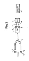
- Figure 5 shows an alternative embodiment of apparatus in which more than one light emitting diode is employed as a current responsive source.
- Light emitting diode 1 is shown as before with the current i to be measured passing therethrough.
- a second light emitting diode 15 is provided, with a constant current i2 passing therethrough.
- the light emitted by the two LEDs 1 and 15 is combined in an optical coupler 16 before impinging on a detector 4 exactly as previously described with reference to Figure 1.
- the colour of the light emitted thereby and hence the light impinging on the detector changes also.
- the colour of this light is determined exactly as before to give an indication of the magnitude of the current i.
- the apparatus can be employed to detect any parameter which can be translated into an electric current.
Landscapes
- Physics & Mathematics (AREA)
- General Physics & Mathematics (AREA)
- Spectrometry And Color Measurement (AREA)
- Measurement Of Current Or Voltage (AREA)
- Measuring Instrument Details And Bridges, And Automatic Balancing Devices (AREA)
Applications Claiming Priority (2)
| Application Number | Priority Date | Filing Date | Title |
|---|---|---|---|
| GB8704539 | 1987-02-26 | ||
| GB878704539A GB8704539D0 (en) | 1987-02-26 | 1987-02-26 | Electrical current measurement |
Publications (1)
| Publication Number | Publication Date |
|---|---|
| EP0284214A1 true EP0284214A1 (fr) | 1988-09-28 |
Family
ID=10612992
Family Applications (1)
| Application Number | Title | Priority Date | Filing Date |
|---|---|---|---|
| EP88301658A Withdrawn EP0284214A1 (fr) | 1987-02-26 | 1988-02-26 | Mesure du courant électrique |
Country Status (7)
| Country | Link |
|---|---|
| EP (1) | EP0284214A1 (fr) |
| JP (1) | JPS63261167A (fr) |
| KR (1) | KR880010330A (fr) |
| CN (1) | CN88101525A (fr) |
| AU (1) | AU1217688A (fr) |
| CA (1) | CA1295682C (fr) |
| GB (2) | GB8704539D0 (fr) |
Cited By (3)
| Publication number | Priority date | Publication date | Assignee | Title |
|---|---|---|---|---|
| EP0613016A1 (fr) * | 1993-01-27 | 1994-08-31 | Hamamatsu Photonics K.K. | Appareil détecteur de tension |
| DE19641186A1 (de) * | 1996-09-24 | 1998-04-02 | Siemens Ag | Schaltungsanordnung zur Strommessung eines Stromleiters zur Ansteuerung von elektrisch steuerbaren Auslöseeinrichtungen |
| WO2005095911A1 (fr) * | 2004-03-31 | 2005-10-13 | The University Of Liverpool | Controle non orthogonal de systemes complexes |
Families Citing this family (3)
| Publication number | Priority date | Publication date | Assignee | Title |
|---|---|---|---|---|
| GB2321713A (en) * | 1997-02-01 | 1998-08-05 | Motorola Israel Ltd | High-voltage transmission line data transfer system |
| CN105185551A (zh) * | 2015-09-22 | 2015-12-23 | 波瑞电气有限公司 | 一种基于可见光通讯的变压器 |
| CN109142840B (zh) * | 2018-09-18 | 2023-07-25 | 江门市新会区炎泰电子有限公司 | 一种电流测量方法及其全光纤漏电流保护器 |
Citations (3)
| Publication number | Priority date | Publication date | Assignee | Title |
|---|---|---|---|---|
| DE3039471A1 (de) * | 1979-10-29 | 1981-05-14 | ASEA AB, Västerås | Anordnung zur messung eines stromes, der ein lichtemittierendes element durchfliesst |
| EP0175358A2 (fr) * | 1984-09-18 | 1986-03-26 | Mitsubishi Denki Kabushiki Kaisha | Dispositif capteur optique |
| US4630218A (en) * | 1983-04-22 | 1986-12-16 | Cooper Industries, Inc. | Current measuring apparatus |
Family Cites Families (2)
| Publication number | Priority date | Publication date | Assignee | Title |
|---|---|---|---|---|
| US4388589A (en) * | 1980-06-23 | 1983-06-14 | Molldrem Jr Bernhard P | Color-emitting DC level indicator |
| US4584523A (en) * | 1983-10-03 | 1986-04-22 | Rca Corporation | Measurement of the current flow in an electric power transmission line by detection of infrared radiation therefrom |
-
1987
- 1987-02-26 GB GB878704539A patent/GB8704539D0/en active Pending
-
1988
- 1988-02-22 CA CA000559417A patent/CA1295682C/fr not_active Expired - Lifetime
- 1988-02-25 AU AU12176/88A patent/AU1217688A/en not_active Abandoned
- 1988-02-26 KR KR1019880001957A patent/KR880010330A/ko not_active Application Discontinuation
- 1988-02-26 GB GB8804563A patent/GB2201798B/en not_active Expired - Lifetime
- 1988-02-26 JP JP63042403A patent/JPS63261167A/ja active Pending
- 1988-02-26 EP EP88301658A patent/EP0284214A1/fr not_active Withdrawn
- 1988-02-26 CN CN198888101525A patent/CN88101525A/zh active Pending
Patent Citations (3)
| Publication number | Priority date | Publication date | Assignee | Title |
|---|---|---|---|---|
| DE3039471A1 (de) * | 1979-10-29 | 1981-05-14 | ASEA AB, Västerås | Anordnung zur messung eines stromes, der ein lichtemittierendes element durchfliesst |
| US4630218A (en) * | 1983-04-22 | 1986-12-16 | Cooper Industries, Inc. | Current measuring apparatus |
| EP0175358A2 (fr) * | 1984-09-18 | 1986-03-26 | Mitsubishi Denki Kabushiki Kaisha | Dispositif capteur optique |
Cited By (5)
| Publication number | Priority date | Publication date | Assignee | Title |
|---|---|---|---|---|
| EP0613016A1 (fr) * | 1993-01-27 | 1994-08-31 | Hamamatsu Photonics K.K. | Appareil détecteur de tension |
| US5583444A (en) * | 1993-01-27 | 1996-12-10 | Hamamatsu Photonics K.K. | Voltage detection apparatus |
| US5703491A (en) * | 1993-01-27 | 1997-12-30 | Hamamatsu Photonics K.K. | Voltage detection apparatus |
| DE19641186A1 (de) * | 1996-09-24 | 1998-04-02 | Siemens Ag | Schaltungsanordnung zur Strommessung eines Stromleiters zur Ansteuerung von elektrisch steuerbaren Auslöseeinrichtungen |
| WO2005095911A1 (fr) * | 2004-03-31 | 2005-10-13 | The University Of Liverpool | Controle non orthogonal de systemes complexes |
Also Published As
| Publication number | Publication date |
|---|---|
| CA1295682C (fr) | 1992-02-11 |
| CN88101525A (zh) | 1988-09-07 |
| AU1217688A (en) | 1988-09-01 |
| KR880010330A (ko) | 1988-10-08 |
| JPS63261167A (ja) | 1988-10-27 |
| GB2201798A (en) | 1988-09-07 |
| GB8704539D0 (en) | 1987-04-01 |
| GB8804563D0 (en) | 1988-03-30 |
| GB2201798B (en) | 1991-07-10 |
Similar Documents
| Publication | Publication Date | Title |
|---|---|---|
| US5334916A (en) | Apparatus and method for LED emission spectrum control | |
| US4880970A (en) | Optical sensors for measurement of a variable parameter | |
| US4054389A (en) | Spectrophotometer with photodiode array | |
| US5844680A (en) | Device and process for measuring and analysing spectral radiation, in particular for measuring and analysing color characteristics | |
| US5471052A (en) | Color sensor system using a secondary light receiver | |
| US7064832B2 (en) | Color and intensity measuring module for test of light emitting components by automated test equipment | |
| US5021645A (en) | Photoelectric color sensor for article sorting | |
| CA1256179A (fr) | Dispositif detecteur de differences dans les coloris | |
| EP0522548A1 (fr) | Senseur de couleur employant des faisceaux de fibres optiques de diamètres différents | |
| EP0081702A1 (fr) | Système électro-optique pour le contrôle de la couleur | |
| CA1168891A (fr) | Systeme optique pour la spectrometrie | |
| US4904088A (en) | Method and apparatus for determining radiation wavelengths and wavelength-corrected radiation power of monochromatic light sources | |
| JP2002522763A (ja) | 繊維色格付けシステム | |
| CA1278069C (fr) | Detecteur optique | |
| JPH10508984A (ja) | 特にオプトエレクトロニクス半導体デバイス用であるオプトエレクトロニクスデバイス用温度補償方法 | |
| EP0284214A1 (fr) | Mesure du courant électrique | |
| JPH03133183A (ja) | 発光ダイオードアレイの試験装置 | |
| EP0251496A2 (fr) | Mesure de température | |
| CA2044419A1 (fr) | Colorimetre industriel a moyen de compensation du vieillissement de la lampe | |
| JPS645644B2 (fr) | ||
| EP0619496A2 (fr) | Capteur de champ magnétique | |
| JPH09325088A (ja) | 発光半導体装置の光度測定方法及び測定装置 | |
| JP2000019106A (ja) | 液体の光透過度測定方法 | |
| GB2234061A (en) | Water monitor | |
| JPS6224125A (ja) | 光半導体測定装置 |
Legal Events
| Date | Code | Title | Description |
|---|---|---|---|
| PUAI | Public reference made under article 153(3) epc to a published international application that has entered the european phase |
Free format text: ORIGINAL CODE: 0009012 |
|
| AK | Designated contracting states |
Kind code of ref document: A1 Designated state(s): AT BE CH DE FR GB IT LI LU NL SE |
|
| RAP1 | Party data changed (applicant data changed or rights of an application transferred) |
Owner name: THE UNIVERSITY OF LIVERPOOL |
|
| 17P | Request for examination filed |
Effective date: 19890426 |
|
| 17Q | First examination report despatched |
Effective date: 19910724 |
|
| STAA | Information on the status of an ep patent application or granted ep patent |
Free format text: STATUS: THE APPLICATION IS DEEMED TO BE WITHDRAWN |
|
| 18D | Application deemed to be withdrawn |
Effective date: 19911206 |