EP0283787B1 - Spezielle Anfahrmethode für die Kupplungssteuerung bei einem stufenlosen Getriebe - Google Patents
Spezielle Anfahrmethode für die Kupplungssteuerung bei einem stufenlosen Getriebe Download PDFInfo
- Publication number
- EP0283787B1 EP0283787B1 EP88103283A EP88103283A EP0283787B1 EP 0283787 B1 EP0283787 B1 EP 0283787B1 EP 88103283 A EP88103283 A EP 88103283A EP 88103283 A EP88103283 A EP 88103283A EP 0283787 B1 EP0283787 B1 EP 0283787B1
- Authority
- EP
- European Patent Office
- Prior art keywords
- clutch
- speed
- engine speed
- signal
- engine
- Prior art date
- Legal status (The legal status is an assumption and is not a legal conclusion. Google has not performed a legal analysis and makes no representation as to the accuracy of the status listed.)
- Expired - Lifetime
Links
Images


Classifications
-
- F—MECHANICAL ENGINEERING; LIGHTING; HEATING; WEAPONS; BLASTING
- F16—ENGINEERING ELEMENTS AND UNITS; GENERAL MEASURES FOR PRODUCING AND MAINTAINING EFFECTIVE FUNCTIONING OF MACHINES OR INSTALLATIONS; THERMAL INSULATION IN GENERAL
- F16H—GEARING
- F16H61/00—Control functions within control units of change-speed- or reversing-gearings for conveying rotary motion ; Control of exclusively fluid gearing, friction gearing, gearings with endless flexible members or other particular types of gearing
- F16H61/66—Control functions within control units of change-speed- or reversing-gearings for conveying rotary motion ; Control of exclusively fluid gearing, friction gearing, gearings with endless flexible members or other particular types of gearing specially adapted for continuously variable gearings
-
- B—PERFORMING OPERATIONS; TRANSPORTING
- B60—VEHICLES IN GENERAL
- B60W—CONJOINT CONTROL OF VEHICLE SUB-UNITS OF DIFFERENT TYPE OR DIFFERENT FUNCTION; CONTROL SYSTEMS SPECIALLY ADAPTED FOR HYBRID VEHICLES; ROAD VEHICLE DRIVE CONTROL SYSTEMS FOR PURPOSES NOT RELATED TO THE CONTROL OF A PARTICULAR SUB-UNIT
- B60W10/00—Conjoint control of vehicle sub-units of different type or different function
- B60W10/02—Conjoint control of vehicle sub-units of different type or different function including control of driveline clutches
-
- B—PERFORMING OPERATIONS; TRANSPORTING
- B60—VEHICLES IN GENERAL
- B60W—CONJOINT CONTROL OF VEHICLE SUB-UNITS OF DIFFERENT TYPE OR DIFFERENT FUNCTION; CONTROL SYSTEMS SPECIALLY ADAPTED FOR HYBRID VEHICLES; ROAD VEHICLE DRIVE CONTROL SYSTEMS FOR PURPOSES NOT RELATED TO THE CONTROL OF A PARTICULAR SUB-UNIT
- B60W10/00—Conjoint control of vehicle sub-units of different type or different function
- B60W10/10—Conjoint control of vehicle sub-units of different type or different function including control of change-speed gearings
- B60W10/101—Infinitely variable gearings
-
- B—PERFORMING OPERATIONS; TRANSPORTING
- B60—VEHICLES IN GENERAL
- B60W—CONJOINT CONTROL OF VEHICLE SUB-UNITS OF DIFFERENT TYPE OR DIFFERENT FUNCTION; CONTROL SYSTEMS SPECIALLY ADAPTED FOR HYBRID VEHICLES; ROAD VEHICLE DRIVE CONTROL SYSTEMS FOR PURPOSES NOT RELATED TO THE CONTROL OF A PARTICULAR SUB-UNIT
- B60W30/00—Purposes of road vehicle drive control systems not related to the control of a particular sub-unit, e.g. of systems using conjoint control of vehicle sub-units, or advanced driver assistance systems for ensuring comfort, stability and safety or drive control systems for propelling or retarding the vehicle
- B60W30/18—Propelling the vehicle
-
- F—MECHANICAL ENGINEERING; LIGHTING; HEATING; WEAPONS; BLASTING
- F16—ENGINEERING ELEMENTS AND UNITS; GENERAL MEASURES FOR PRODUCING AND MAINTAINING EFFECTIVE FUNCTIONING OF MACHINES OR INSTALLATIONS; THERMAL INSULATION IN GENERAL
- F16H—GEARING
- F16H61/00—Control functions within control units of change-speed- or reversing-gearings for conveying rotary motion ; Control of exclusively fluid gearing, friction gearing, gearings with endless flexible members or other particular types of gearing
- F16H61/66—Control functions within control units of change-speed- or reversing-gearings for conveying rotary motion ; Control of exclusively fluid gearing, friction gearing, gearings with endless flexible members or other particular types of gearing specially adapted for continuously variable gearings
- F16H61/662—Control functions within control units of change-speed- or reversing-gearings for conveying rotary motion ; Control of exclusively fluid gearing, friction gearing, gearings with endless flexible members or other particular types of gearing specially adapted for continuously variable gearings with endless flexible members
- F16H61/66254—Control functions within control units of change-speed- or reversing-gearings for conveying rotary motion ; Control of exclusively fluid gearing, friction gearing, gearings with endless flexible members or other particular types of gearing specially adapted for continuously variable gearings with endless flexible members controlling of shifting being influenced by a signal derived from the engine and the main coupling
-
- B—PERFORMING OPERATIONS; TRANSPORTING
- B60—VEHICLES IN GENERAL
- B60W—CONJOINT CONTROL OF VEHICLE SUB-UNITS OF DIFFERENT TYPE OR DIFFERENT FUNCTION; CONTROL SYSTEMS SPECIALLY ADAPTED FOR HYBRID VEHICLES; ROAD VEHICLE DRIVE CONTROL SYSTEMS FOR PURPOSES NOT RELATED TO THE CONTROL OF A PARTICULAR SUB-UNIT
- B60W2510/00—Input parameters relating to a particular sub-units
- B60W2510/02—Clutches
- B60W2510/0283—Clutch input shaft speed
-
- B—PERFORMING OPERATIONS; TRANSPORTING
- B60—VEHICLES IN GENERAL
- B60W—CONJOINT CONTROL OF VEHICLE SUB-UNITS OF DIFFERENT TYPE OR DIFFERENT FUNCTION; CONTROL SYSTEMS SPECIALLY ADAPTED FOR HYBRID VEHICLES; ROAD VEHICLE DRIVE CONTROL SYSTEMS FOR PURPOSES NOT RELATED TO THE CONTROL OF A PARTICULAR SUB-UNIT
- B60W2510/00—Input parameters relating to a particular sub-units
- B60W2510/06—Combustion engines, Gas turbines
- B60W2510/0604—Throttle position
-
- B—PERFORMING OPERATIONS; TRANSPORTING
- B60—VEHICLES IN GENERAL
- B60W—CONJOINT CONTROL OF VEHICLE SUB-UNITS OF DIFFERENT TYPE OR DIFFERENT FUNCTION; CONTROL SYSTEMS SPECIALLY ADAPTED FOR HYBRID VEHICLES; ROAD VEHICLE DRIVE CONTROL SYSTEMS FOR PURPOSES NOT RELATED TO THE CONTROL OF A PARTICULAR SUB-UNIT
- B60W2540/00—Input parameters relating to occupants
- B60W2540/16—Ratio selector position
-
- F—MECHANICAL ENGINEERING; LIGHTING; HEATING; WEAPONS; BLASTING
- F16—ENGINEERING ELEMENTS AND UNITS; GENERAL MEASURES FOR PRODUCING AND MAINTAINING EFFECTIVE FUNCTIONING OF MACHINES OR INSTALLATIONS; THERMAL INSULATION IN GENERAL
- F16H—GEARING
- F16H63/00—Control outputs from the control unit to change-speed- or reversing-gearings for conveying rotary motion or to other devices than the final output mechanism
- F16H63/40—Control outputs from the control unit to change-speed- or reversing-gearings for conveying rotary motion or to other devices than the final output mechanism comprising signals other than signals for actuating the final output mechanisms
- F16H63/46—Signals to a clutch outside the gearbox
Definitions
- the present invention relates to a method for controlling torque transfer at a clutch in a continuously variable transmission system.
- CVT's continuously variable transmissions
- US-A-4,522,086 and U.S.-A-4,458,318 These patents generally describe the mechanics and controls for a CVT system utilizing two adjustable pulleys, each pulley having at least one sheave which is axially fixed and another sheave which is axially movable relative to the first sheave.
- a flexible belt of metal or elastomeric material intercouples the pulleys.
- the interior faces of the pulley sheaves are beveled or chamfered.
- the displaceable sheave includes a fluid constraining chamber for receiving fluid to move the sheave and thus change the effective pulley diameter; as fluid is exhausted from the chamber, the pulley diameter changes in the opposite sense.
- the effective diameter of one pulley is adjusted in one direction as the effective diameter of the second pulley is varied in the opposite direction, thereby effecting a change in the drive ratio between the input shaft coupled to an input pulley and an output shaft coupled to an output pulley.
- the ratio changes continuously as the pulley diameters vary.
- Such transmissions frequently are referred to in the art as a continuously variable transmission, CVT.
- the object of the present invention lies in the provision of clutch control techniques for continuously variable transmission driven vehicles during driving conditions in which total torque in the vehicle system tends to accelerate the engine upon clutch engagement, for example, during a transition from "hold” to "lock-up".
- the present invention generally provides a clutch control technique for a continuously variable transmission in various driving situations. Recognition of conditions when total torque in the continuously variable transmission driven vehicle system will tend to accelerate the engine indicates special driving conditions. Normal clutch control, which controls engine speed explicitly in response to driver demand, is bypassed at this time. A maximum torque schedule, based on driver demand, and clutch slip speed measurement control the clutch pressure set point for regulating a modulation signal to a clutch control valve and, hence, the pressure at the clutch. The clutch may then be returned to a lock-up position through a gradual process which gives a natural feeling response to a driver while providing a requisite system operation. The clutch control may also be returned to one of the operating modes dependent upon other system characteristics.
- a throttle signal 10 controls the operation of an engine 12 which transmits torque via shaft 14 to a primary pulley 16 in a CVT 18.
- a flywheel and damping arrangement may be included on shaft 14 between the engine 12 and the primary pulley 16.
- a metal or elastomeric belt 20 connects the primary pulley 16 to a secondary pulley 22 to transmit torque to a second shaft 24.
- a pump 26 may also be driven by the first shaft 14 to provide line pressure for the hydraulic system and the controls of the CVT 18.
- the second shaft 24 drives the input to a clutch 28 which in turn provides a torque to a third shaft 30.
- the third shaft 30 drives a reduction differential gear arrangement 32 as a drive line to provide power to the vehicle wheels 34.
- an electronic controller 36 receives throttle, engine speed, clutch input speed, clutch output speed, clutch pressure, temperature, driver demand, idle, shift lever and other information input signals as shown at the left of FIG. 1.
- the electronic controller 36 operates in a logical fashion to provide a ratio control signal on a line 38, a line pressure control signal on a line 40 and a clutch control signal on a line 42.
- the signal on the line 38 to a ratio control valve 44 controls the hydraulic pressure on a line 46 to the primary pulley 16 of the CVT 18 to control the ratio between the primary pulley 16 and the secondary pulley 22, i.e. , the belt ratio.
- the signal on the line 40 communicates with a line pressure regulator 48 which via a line 50 provides line pressure from fluid flow delivered by the pump 26 to the ratio control valve 44, a clutch control valve 52 and the secondary pulley 22.
- the output of the line pressure regulator on the line 50 also controls the pressure at the secondary pulley 22 to insure that the belt 20 does not slip.
- the output signal on the line 42 to the clutch control valve 52 controls the output of the clutch control valve 52 on a line 54 to the manual and servo valves 56 which controls the fluid flow on the line 58 to the clutch 28. This is the signal which controls or which provides the pressure at the clutch 28 and hence regulates the torque transfer from the second shaft 24 to the third shaft 30.
- a shift lever signal on a line 60 provides an additional control of the manual and servo valves 56.
- the shift lever signal on the line 60 indicates that the vehicle is in a neutral or park mode
- the manual control within the valve arrangement 56 is closed. This prevents fluid from flowing to the clutch 28 and thus prevents any torque transfer through the clutch 28 when the vehicle is in the neutral mode.
- the ratio of NE to NCI will correspond to and provide a measure of the transmission belt ratio.
- the difference between NCI and NCO provides a measure of the slippage at the clutch 28.
- NCI equals NCO, the clutch 28 is locked-up with no slippage.
- a related application for an Continuously Variable Transmission Clutch Control System also incorporates a sixth mode - an engage mode - which provides a transition between neutral and hold modes.
- NEUTRAL MODE The driver manually places the shift lever in a neutral or park position. This closes the manual valve to the clutch which prevents any pressure from being applied to the clutch plates. If the vehicle speed is low, the ratio control will downshift the continuously variable driven transmission to full low. If the vehicle is at a significant speed, the ratio control will attempt to synchronize the clutch input and output speeds. This enables a more rapid clutch re-engagement should the shift lever be moved from neutral to drive while the vehicle is still at a significant speed. Also, the desired control signal to the clutch control valve during this mode is a "full-on" signal.
- HOLD MODE The system may enter this mode whenever the shift lever is in a position other than neutral or park. This opens the manual valve and allows pressure to be applied to the clutch plates.
- the clutch pressure loop strokes the clutch by means of a pulse width modulation (PWM) operated electrohydraulic control valve.
- PWM pulse width modulation
- the clutch pressure loop maintains a predetermined constant pressure on the clutch for vehicle "creep". This corresponds to the pressure which overcomes the biasing spring and brings the clutch plates into contact.
- the ratio control operation in this mode is the same as during the neutral mode.
- NORMAL START MODE In response to a driver demand at the throttle, the system modulates the clutch pressure to control the engine speed to an engine speed setpoint obtained from a schedule that is a function of the throttle as explained in EP-A-281 849 The clutch pressure regulates the amount of vehicle load torque to the engine.
- the normal start mode can be used only if a total torque (engine torque and vehicle torque) flows in a direction which would tend to accelerate the vehicle.
- the ratio control maintains the belt ratio throughout the start mode so as not to interact with clutch control of the engine speed.
- SPECIAL START MODE In situations in which the flow of total torque would tend to accelerate the engine from the existing torque of the moving vehicle, special start mode should be used to engage the clutch with or without driver demand.
- Driving conditions may exist for operation of the special start mode in a variety of circumstances, all of which tend to accelerate the engine due to the inertia of the moving vehicle, for example, 1) when a driver shifts from drive to neutral and back into drive before the vehicle slows to a speed where the vehicle inertia torque is insignificant; 2) when a vehicle is rolling down a hill and the driver shifts from neutral into drive; and 3) when the vehicle is skidding on ice or otherwise and the driver removes the braking force while significant vehicle speed remains.
- FIG. 2 therein is shown an overall logic flow chart for selection between the various operating modes for the clutch control system.
- the following table provides exemplary reference points for engine speed, referenced in the flow chart on Fig. 2:
- an initial determination is performed at a decision block 300 to determine whether the manual shift lever is at neutral or park. If the shift lever is at neutral or park, the system enters a neutral mode for operation as described above. If the shift lever is not in neutral or park, the system determines, at block 302 whether the clutch is stroking (this corresponds to the engage mode discussed in EP-A-281 849. If the clutch is stroking, then the system remains in the neutral mode.
- both of the normal and special start flags are reset at block 304 and the system determines, at a block 306, whether the clutch output speed is less than some minimum clutch output speed. If yes, the system downshifts at a block 308 through an appropriate signal to the ratio control system and loops back to a start block 310 to determine an appropriate mode. If the clutch output speed is not less than the minimum speed, the system attempts to synchronize the clutch input speed and the clutch output speed at a block 312, again by an appropriate signal to the ratio control system, and loops back to start at block 310.
- the system determines whether it is not in a neutral mode, it then determines whether the clutch is locked at a decision block 314. If no, then the system determines that the drive mode has not been entered and advances to a further determination. However, if the clutch is locked as determined at the block 314, then the system determines whether the engine speed is less than the clutch disengage speed at a block 316. If no, meaning that the clutch is locked and the engine speed is not below the clutch disengage speed, then the system enters the drive mode and resets the start flags at a block 318. The ratio control system then controls the engine speed and the clutch pressure is in a full-on state as shown at a block 320. The system then loops back to the start block 310.
- the system determines whether driver demand exists at a decision block 322. If no, at decision block 324 the system then determines whether the clutch output speed times the transmission belt ratio is less than the clutch disengage speed or greater than the maximum engine speed. If yes, then the system enters the hold mode and resets the start flags at a block 326.
- driver demand has been used synonymously with the term throttle.
- throttle and driver demand represent the vehicle driver stepping down on, or into, the accelerator pedal.
- driver demand must be viewed as broader than throttle.
- a driver may create a demand by depressing the accelerator a specific amount; if a small dead band exists in the throttle response, such a depression (demand) may not result in a throttle variation depending upon the size of the dead band.
- a driver demand, non-the-less, would exist under these conditions.
- the decision block 322 looks at driver demand in the broader sense, without regard to the existence of a variation in throttle.
- the pressure control signal is held at the touch off pressure, i.e. , that pressure just significant to overcome the clutch spring and to bring the clutch plates into contact.
- the system also compares the clutch output speed to the minimum clutch output speed at a block 330. If the clutch output speed is less than the minimum speed, then the system downshifts at a block 332 and loops back to the start block 310. If the clutch output speed is not less than the minimum speed, the system attempts to synchronize the clutch input speed with the clutch output speed at a block 334 and loops back to the start block 310.
- the system sets a special start flag at a block 336.
- the speed check at the decision block 324 monitors the torque flow for the total vehicle system.
- the speed check of RB x NCO ⁇ NED determines if a clutch re-engagement at these conditions will cause the engine to stall.
- the speed check of RB x NCO ⁇ NEH will determine if the engine speed will be greater than the maximum allowable engine speed in a clutch re-engagement. If one of the two conditions are true, the clutch will remain in hold mode. Otherwise, the system will set the special start flag to allow the system to operate in the special start mode (NEH > Rb ⁇ NCO > NED) to allow the clutch to re-engage to a lock-up condition.
- the system advances to a block 338, which is the same point to which it advances if a driver demand is recognized at the decision block 322.
- the system determines whether a normal start flag has been set. If yes, then the system advances to the normal start mode as shown by the line 340. In a normal start mode, the system maintains the belt ratio and controls the engine speed through the clutch pressure as shown at a block 342 and explained in more detail in EP-A-281 849.
- the system determines whether a special start flag has been set at a block 344. If yes, then the system determines whether the engine speed is less than the clutch disengage speed at a block 346. If yes, then the system resets the special start flag and sets the normal start flag at a block 348 and advances to the normal start mode as shown at the line 340. At that point, normal start mode operation occurs as explained above.
- the system of the preferred embodiment performs the comparison of the decision block 346 (NE ⁇ NED) even if a special start flag has been set, because clutch control under the special start mode parameters does not control engine speed. Without engine speed control, the engine may be stalled undesirably. Accordingly, when engine speed is less than the clutch disengage speed, the system returns to normal start mode operation. In this mode (normal start), engine speed is controlled and engine stalling can be prevented.
- the system maintains the special start mode as shown at the line 350.
- the system maintains the belt ratio and increments the pressure control setpoint as shown at a block 352 and explained more fully below. The system then loops back to the start block 310.
- the system advances to a decision block 354, at which it determines whether the transmission belt ratio times the clutch output speed is less than the lowest engine speed setpoint obtained from the normal start mode engine speed schedule. Once again, the system at this block monitors the direction of total torque flow. If yes, then the system sets a normal start flag at a block 356 and advances to the normal start mode for operation as explained above. If no, then the system advances to a block 358, sets the special start flag and enters the special start mode for operation.
- FIG. 3 therein is shown a block diagram for a clutch control system such as that described in EP-A-281 849.
- the throttle input signal on line 360 provides a feed forward pressure signal from an open control loop 362 to a summing junction 364.
- a throttle signal on the line 360 also goes to a closed loop engine speed control system 366 which provides a second input as an error signal to the summing junction 364.
- the output of summing junction 364 on a line 368 provides a pressure setpoint to a pressure control loop 370.
- the operation of the system illustrated in Fig. 3 may be more fully understood from referenced to EP-A-281 849.
- control loop 364 In that application the operation of the feed forward loop 362 (identified therein as control loop 364), the engine speed control loop 366 (identified therein as control loop 68) and the pressure loop control system 370 (identified therein as control loop 110) is set forth more fully.
- the co-pending application (EP-A-281 849) concerns the generation of a pressure setpoint at the line 368 to control, or to provide a setpoint for, the pressure control loop 370. If the block 372 is thought of as a switch, the external setpoint may be provided at a line 374 and the switch 372 toggled or selected when the special start mode conditions with which the present application is concerned have been recognized.
- the pressure control loop 370 then operates in a fashion described in the co-pending application in response to the external setpoint signal received on the line 374 for a special start mode operation.
- the present system may be viewed as substituting for that of the referenced co-pending application during special start conditions.
- FIG. 4 therein is shown a block diagram of a system for providing a clutch pressure setpoint to the pressure control loop 370 during special start mode circumstances.
- the system in FIG. 4 may be thought of as substituting for the feed forward loop 362 and the engine speed control loop 866 to provide a clutch pressure setpoint to the pressure control loop 370.
- the system of FIG. 4 receives a clutch input speed on a line 376 and a clutch output speed at a line 378 to a summing junction 380 which generates a difference signal (clutch input speed minus clutch output speed) at a line 382.
- a summing junction 380 which generates a difference signal (clutch input speed minus clutch output speed) at a line 382.
- the absolute value of the difference value from the line 382 is generated and then provided to a summing junction 385.
- a constant value from a line 386 is added to that absolute value.
- the signal is then multiplied by a gain factor (KINT.) and integrated at a block 388 in conjunction with initial conditions from a line 390 to provide a first clutch pressure setpoint at a line 392 to a summing junction 394.
- KINT. gain factor
- the preferred embodiment desirably integrates the absolute value signal from the function block 384 to provide an increasing error signal in response to a difference between clutch input speed and clutch output speed. This tends to increase the pressure setpoint signal to increase the clutch pressure which tends to diminish the difference between clutch input speed and clutch output speed. Integration also provides a more desirable response in terms of vehicle driveability and driver expectations.
- the system of FIG. 4 also receives a throttle position signal at a line 396, which at a block 398 provides a corresponding maximum torque feed forward value on a line 400.
- This signal passes through a first order filter 402 which in conjunction with an initial condition from a line 404 provides a modified maximum torque feed forward signal at a line 406.
- the signal from the line 406 is multiplied by the transmission belt ratio (RB) and divided by the clutch gain (CG) to provide a second input to the summing junction 394 on a line 410.
- the function of the block 408 is equivalent to that of blocks 82 and 86 in related, co-pending applications.
- the feed forward torque, multiplied by the belt ratio may be multiplied by the inverse clutch gain (ATTCLU) to achieve the same result. This may be preferable in microprocessor systems.
- the combination of the signals from the lines 392 and 410 is provided by summing junction 394 at a line 412 to provide a clutch pressure setpoint to the pressure control loop 370.
- the system looks at the absolute value of the difference between the clutch input speed and the clutch output speed. This value is then integrated to provide a clutch pressure error signal which increases the clutch pressure setpoint as appropriate. This change in clutch pressure tends to match the clutch input speed with the clutch output speed to generate a correspondingly smaller difference signal and hence a smaller integrated value, as the loop continues to operate. Accordingly, a large differential between the clutch input speed and the clutch output speed is gradually corrected to provide a smooth transition back to a lock up of the clutch, indicated by clutch input speed equalling clutch output speed.
- a constant on the line 386 is added to provide a positive lockup at that point.
- the addition of the constant provides a slight ramping output from the integrating step 388.
- the initial condition on the line 390 is chosen as zero. This prevents a jump at such times as the special start mode may be initiated.
- the system loop 450 in Figure 4 may be used in some applications to provide the sole indicia of appropriate clutch pressure during special start conditions.
- a driver may increase his demand and thereby increase the throttle, which can cause the engine to race in the special start mode.
- the pressure on the clutch does not control the engine speed and the engine can race undesirably, this provides an unexpected response for the driver and may damage the engine.
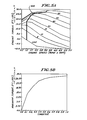
- the throttle position is monitored in the special start mode to provide a maximum torque signal.
- This maximum torque signal may be derived from an engine map as FIG. 5A.
- FIG. 5A a maximum torque has been chosen for each throttle setting desirably to prevent the engine from racing in the special start mode in response to increased driver demand.
- the graph of FIG. 5B represents a function of the maximum torque against specific throttle settings corresponding to the line 414 of FIG. 5A.
- the system can determine a maximum torque from FIG. 5B as a function of specific throttle settings.
- the first order filter 402 slows this response as a function chosen for the filter (these may be chosen empirically to provide a realistic driving response).
- the initial condition on line 404 is chosen to be equal to zero in the preferred embodiment to preclude lurching of the vehicle when the system is first initiated. Multiplying the output of this filter by the belt ratio (RB) and dividing by the clutch gain (CG) (or multiplying by the inverse clutch gain) converts the maximum torque to a pressure signal which is combined with that from the clutch input speed-clutch output speed differential loop to provide a desired clutch pressure setpoint on line 412.
- FIG. 6 therein is shown a flowchart for clutch slip speed loop 450 of FIG. 4.
- the logic flow chart proceeds from a logic start block 452 to the set initial condition flag block 454.
- the initial flag set is then checked at a decision block 456. If the flag has been set, the initial condition for integration at the system block 388 is set at zero at a block 458, and the initial condition flag is reset at a block 460.
- the system then branches back to a block 462, which it proceeds to from the decision block 456 if the initial condition flag has not been set.
- the system generates an error signal representing the difference between clutch input speed and clutch output speed.
- the system provides the absolute value of that error signal from the block 462. The absolute value is multiplied by the integral gain and is then integrated at a block 466 to provide a clutch pressure setpoint at a block 468.
- the system then loops back to decision block 456.
- FIG. 6 may be modified slightly to provide a positive lock-up pressure when the clutch input speed equals clutch output.
- the addition of a constant value signal prior to the integration function block 466 provides just such a set output signal.
- the block diagram of FIG. 4 illustrates this operation at the summing junction 385. This operation desirably facilitates transfer of the system operating mode back to normal start or drive control.
- FIG. 7 therein is shown a flow chart representing the operation of the maximum torque feed forward 470 in conjunction with the clutch slip speed loop 450 from FIG. 4.
- the system advances from a start block 472 to set the initial condition flags at a block 474.
- the initial condition flag is then monitored at a decision block 476. If it has been set, then the system at block 478 sets the initial condition of zero for integration (at system function block 388 of FIG. 4) and at block 480 sets the initial condition of zero for filtering (at system function block 402 of FIG. 4).
- the system then resets the initial condition flag at a block 482 and branches back to a block 484, to which the system proceeds from the decision block 476 if the initial condition flag was not set.
- the system generates an error signal representative of the difference between the clutch input speed and the clutch output speed and advances to a next block 486.
- the system determines the absolute value of the signal from block 484 and advances to a next block 488.
- the system integrates the absolute value signal multiplied by the integral gain from the block 486 (at this point a constant may be added to the absolute value and integrated also) and advances to a next block 490.
- the maximum feed forward torque is determined from the throttle setting and provided to the feed forward filter at a next block 492.
- the system filters the feed forward maximum torque signal and the system provides the filtered signal to a next block 494.
- the feed forward torque signal is converted to a feed forward pressure by multiplying the torque signal by the belt ratio and dividing by the clutch gain.
- the system determines a clutch pressure setpoint as the sum of the feed forward pressure and the output of the integrator. The system then loops back to the decision block 476 to again examine the status of the initial condition flags.
- Temperature compensation over the expected range of operating temperatures may be accomplished as taught in EP-A-281 947.
- pulse width modulation for use in the preferred embodiment may be accomplished as taught in EP-A-281 944.
Claims (11)
- Verfahren zum Steuern der Drehmomentübertragung einer Kupplung (28) in einem kontinuierlich veränderlichen Getriebe mit folgenden Schritten:a) die Bedingungen (354), bei denen das Trägheitsmoment des Systems den Motor (12) zu beschleunigen sucht, werden festgestellt,b) eine spezielle Startbetriebsart wird aus mehreren Kupplungsbetriebsarten abhängig von den Bedingungen (354) ausgewählt,c) die Drehmomentübertragung der Kupplung (28) wird gesteuert, indem ein Kupplungsdruck-Ansprechpunkt (bei 412) gemäß einem vorbestimmten Programm bestimmt wird, das auf dem Fahrer-Bedarf (10) und der Kupplungsschlupfdrehzahl (bei 380) basiert.
- Verfahren nach Anspruch 1, dadurch gekennzeichnet, daß die Motordrehzahl (NE), die Kupplungsposition (302), der Fahrerbedarf (10) und die Kupplungsausgangsdrehzahl (NCO) anzeigende Bedingungen festgestellt werden, die für einen gewünschten Übergang von einer ersten Betriebsweise des Systems auf die spezielle Startbetriebsweise maßgeblich sind, wobei der Übergang anzeigt, daß das System in einer Start-Steuerbetriebsart betrieben werden soll, daß das System in der ersten Start-Steuerbetriebsart arbeitet, wenn die ermittelten Bedingungen (354) nicht anzeigen, daß bei betätigter Kupplung eine Motorbeschleunigung erfolgt und daß das System in der speziellen Startbetriebsart arbeitet, wenn die ermittelten Bedingungen anzeigen, daß bei betätigter Kupplung eine Motorbeschleunigung erfolgt.
- Verfahren nach Anspruch 2, bei dem in der ersten Start-Steuerbetriebsart die Motordrehzahl (NE) durch den Kupplungsdruck gesteuert wird.
- Verfahren nach einem der Ansprüche 1 bis 3, gekennzeichnet durch folgenden Schritt nach Eintritt des Systems in die spezielle Startbetriebsart:
das Ermitteln der Bedingungen wird wiederholt und das System in die erste Start-Steuerbetriebsart versetzt, wenn die ermittelten Bedingungen nicht weiter anzeigen, daß bei betätigter Kupplung eine Motorbeschleunigung erfolgt. - Verfahren nach einem der Ansprüche 1 bis 4, bei dem das kontinuierlich veränderliche Getriebe mindestens eine zugehörige Motordrehzahl (NED) für das Lösen der Kupplung, einen niedrigsten Motordrehzahlansprechpunkt (NEC) und eine maximale Motordrehzahl (NEH) aufweist und mindestens in einer normalen Startbetriebsart zur Kupplungssteuerung und der speziellen Startbetriebsart zur Kupplungssteuerung arbeitet, dadurch gekennzeichnet, daß beim Lösen der Kupplung die Fahrzeuggeschwindigkeit gemessen wird, eine Motordrehzahl berechnet wird, die der gemessenen Fahrzeuggeschwindigkeit entspricht, wenn die Kupplung betätigt ist, daß die berechnete Motordrehzahl mit der maximalen Motordrehzahl (NEH) und der Motordrehzahl (NED) zum Lösen der Kupplung verglichen wird, um zu bestimmen, ob die berechnete Motordrehzahl entsprechend der gemessenen Fahrzeuggeschwindigkeit zwischen diesen Werten liegt und daß das System in die spezielle Startbetriebsart umgeschaltet wird (372), wenn die gemessene Fahrzeuggeschwindigkeit nicht zwischen den Werten liegt.
- Verfahren nach Anspruch 5, bei dem festgestellt wird, wenn das System in der speziellen Startbetriebsart ist, die Motordrehzahl (NE) gemessen wird, die gemessene Motordrehzahl mit der Kupplungslösedrehzahl (NED) verglichen wird und das System in die normale Startbetriebsart umgeschaltet wird (346), wenn die gemessene Motordrehzahl kleiner ist als die Kupplungslösedrehzahl.
- Verfahren nach Anspruch 6, bei dem die Fahrzeuggeschwindigkeit (NCO) gemessen wird, die gemessene Fahrzeuggeschwindigkeit (NCO) mit einem Faktor vergrößert wird, der dem Übersetzungsverhältnis des Riemengetriebes (RB) proportional ist, die vergrößerte Fahrzeuggeschwindigkeit (354) mit dem niedrigsten Motordrehzahlansprechpunkt (NEC) verglichen wird, das System in die spezielle Startbetriebsart umgeschaltet wird, wenn die vergrößerte Fahrzeuggeschwindigkeit größer ist als der niedrigste Motordrehzahlansprechpunkt und das System in die normale Startbetriebsart umgeschaltet wird, wenn die vergrößerte Fahrzeuggeschwindigkeit kleiner ist als der niedrigste Motordrehzahlansprechpunkt.
- Verfahren nach einem der Ansprüche 1 bis 7 zum Erzeugen eines Kupplungssteuersignals in einem kontinuierlich veränderlichen Getriebe (18), wobei das Signal einer strömungsmittelbetätigten Kupplung (28) zum Übertragen von Drehmoment zwischen einem Motor (12) und einem Antriebsstrang (30, 32) des Fahrzeuges zugeführt wird, die Kupplung eine zugehörige Leitung (58) aufweist, um die Kupplung zum Betätigen mit Strömungsmittel zu beaufschlagen und Strömungsmittel zum Lösen der Kupplung abzuführen mit einer Ventilanordnung (52) in der Strömungsmittelleitung, wobei die Eingangsdrehzahl (376) und die Ausgangsdrehzahl (378) der Kupplung gemessen werden und mindestens ein Drehzahldifferenzdrucksignal (382) erzeugt wird, dadurch gekennzeichnet, daß der Fahrerbedarf (396) gemessen wird, ein vorbestimmtes maximales Drehmomentensignal (398) abhängig vom Fahrerbedarf erzeugt wird, das maximale Drehmomentsignal in ein vorwärts gerichtetes Drucksignal (408) umgewandelt wird und das vorwärts gerichtete Drucksignal mit dem Drehzahldifferenzdrucksignal für das Steuerventil der Kupplung kombiniert wird.
- Verfahren nach Anspruch 8, bei dem der Schritt des Erzeugens eines Ausgangssignals beinhaltet: ein Signal (384) wird erzeugt, das den Absolutwert der Differenz zwischen der Kupplungseingangs- und Kupplungsausgangsdrehzahl repräsentiert und das absolute Ventilsignal (388) wird integriert, um ein Drehzahldifferenzdrucksignal für das Steuerventil der Kupplung zu erzeugen.
- Verfahren nach Anspruch 9, bei dem ein ausgewählter Konstantwert (386) zu dem Drehzahldifferenzsignal vor dem Integrieren addiert wird.
- Verfahren nach einem der Ansprüche 8 bis 10, bei dem ferner das vorbestimmte maximale Drehmomentsignal gefiltert wird (402), um plötzliche Änderungen im Drehmomentsignal zu glätten.
Applications Claiming Priority (2)
| Application Number | Priority Date | Filing Date | Title |
|---|---|---|---|
| US2547687A | 1987-03-13 | 1987-03-13 | |
| US25476 | 1987-03-13 |
Publications (2)
| Publication Number | Publication Date |
|---|---|
| EP0283787A1 EP0283787A1 (de) | 1988-09-28 |
| EP0283787B1 true EP0283787B1 (de) | 1992-04-22 |
Family
ID=21826294
Family Applications (1)
| Application Number | Title | Priority Date | Filing Date |
|---|---|---|---|
| EP88103283A Expired - Lifetime EP0283787B1 (de) | 1987-03-13 | 1988-03-03 | Spezielle Anfahrmethode für die Kupplungssteuerung bei einem stufenlosen Getriebe |
Country Status (3)
| Country | Link |
|---|---|
| EP (1) | EP0283787B1 (de) |
| JP (1) | JP2872671B2 (de) |
| DE (1) | DE3870293D1 (de) |
Families Citing this family (4)
| Publication number | Priority date | Publication date | Assignee | Title |
|---|---|---|---|---|
| US5314050A (en) * | 1992-12-09 | 1994-05-24 | Eaton Corporation | Clutch mode control logic |
| CN106133372B (zh) * | 2014-04-03 | 2018-10-02 | 丰田自动车株式会社 | 车辆控制系统和车辆控制方法 |
| EP3466782B1 (de) | 2017-10-06 | 2021-08-25 | Perkins Engines Company Limited | Anfahrsteuerungsverfahren für ein fahrzeug |
| SE542091C2 (en) * | 2017-11-03 | 2020-02-25 | Scania Cv Ab | A gearbox and a method for controlling a gearbox to achieve a freewheeling mode |
Citations (2)
| Publication number | Priority date | Publication date | Assignee | Title |
|---|---|---|---|---|
| GB2165914A (en) * | 1984-10-20 | 1986-04-23 | Sachs Systemtechnik Gmbh | Clutch equipment for a motor vehicle |
| DE3531434A1 (de) * | 1985-09-03 | 1987-03-12 | Phb Weserhuette Ag | Steuerung fuer rutschkupplungen |
Family Cites Families (9)
| Publication number | Priority date | Publication date | Assignee | Title |
|---|---|---|---|---|
| DE2658719A1 (de) * | 1976-12-24 | 1978-06-29 | Bosch Gmbh Robert | Vorrichtung zur steuerung eines stufenlosen riemengetriebes |
| JPS5939217Y2 (ja) * | 1980-07-14 | 1984-11-01 | 東洋電機製造株式会社 | 電磁クラッチの滑り調整装置 |
| DE3036327A1 (de) * | 1980-09-26 | 1982-05-27 | Volkswagenwerk Ag, 3180 Wolfsburg | Antrieb fuer ein fahrzeug, insbesondere fuer strassenfahrzeug |
| US4458318A (en) * | 1981-04-24 | 1984-07-03 | Borg-Warner Corporation | Control arrangement for a variable pulley transmission |
| US4610183A (en) * | 1983-10-31 | 1986-09-09 | Mazda Motor Corporation | Control of a steplessly variable vehicle transmission |
| DE3404156A1 (de) * | 1984-02-07 | 1985-08-14 | Daimler-Benz Ag, 7000 Stuttgart | Einrichtung zur automatischen betaetigung einer kupplung von fahrzeugen waehrend des anfahrens |
| US4718308A (en) * | 1985-03-29 | 1988-01-12 | Borg-Warner Automotive, Inc. | Hydraulic control system for continuously variable transmission |
| US4648496A (en) * | 1985-04-12 | 1987-03-10 | Borg-Warner Automotive, Inc. | Clutch control system for a continuously variable transmission |
| JPS63110045A (ja) * | 1986-10-24 | 1988-05-14 | Daihatsu Motor Co Ltd | 直結機構付無段変速機の切換制御方法 |
-
1988
- 1988-03-03 EP EP88103283A patent/EP0283787B1/de not_active Expired - Lifetime
- 1988-03-03 DE DE8888103283T patent/DE3870293D1/de not_active Expired - Fee Related
- 1988-03-11 JP JP63058097A patent/JP2872671B2/ja not_active Expired - Fee Related
Patent Citations (2)
| Publication number | Priority date | Publication date | Assignee | Title |
|---|---|---|---|---|
| GB2165914A (en) * | 1984-10-20 | 1986-04-23 | Sachs Systemtechnik Gmbh | Clutch equipment for a motor vehicle |
| DE3531434A1 (de) * | 1985-09-03 | 1987-03-12 | Phb Weserhuette Ag | Steuerung fuer rutschkupplungen |
Also Published As
| Publication number | Publication date |
|---|---|
| EP0283787A1 (de) | 1988-09-28 |
| DE3870293D1 (de) | 1992-05-27 |
| JP2872671B2 (ja) | 1999-03-17 |
| JPS63242738A (ja) | 1988-10-07 |
Similar Documents
| Publication | Publication Date | Title |
|---|---|---|
| US5206805A (en) | Continuously variable transmission clutch control system including special start mode operation | |
| EP0281849B1 (de) | Kupplungssteuerungssystem für stufenloses Getriebe | |
| EP0352551B1 (de) | Hochschaltlogik | |
| US4852006A (en) | Amt off-highway downshift logic | |
| US5168778A (en) | CVT downshift control strategy to minimize slip at the drive pulley | |
| US5603672A (en) | Method for controlling the output torque of an automatic transmission | |
| US4916979A (en) | On-grade shift logic with provision for skip downshifts | |
| US5056637A (en) | System for controlling speed of an engine for a motor vehicle having a continuously variable transmission | |
| EP1113198B1 (de) | Einrichtung zur Ermittlung der Strassenneigung und Steuerung für die Anfahrkupplung | |
| CA2043607C (en) | Coast-sync-coast downshift control method for clutch-to-clutch transmission shifting | |
| EP0242127B1 (de) | Steuersystem für eine Fahrzeugkupplung | |
| GB2097074A (en) | Transmission control system in a vehicle | |
| GB2263519A (en) | System for controlling a continuously-variable transmission for a motor vehicle | |
| EP0417909B1 (de) | Regelungsverfahren und Vorrichtung zur Regelung eines stufenlosen Getriebes | |
| EP0373865A2 (de) | Steuerungssystem für das Übersetzungsverhältnis eines stufenlos verstellbaren Getriebes | |
| US4986396A (en) | Control system for a clutch of a motor vehicle | |
| EP3056772A1 (de) | Steuerungsvorrichtung für stufenloses getriebe mit hilfsgetriebe | |
| US6067493A (en) | Speed change ratio controller for continuously variable transmission | |
| EP0415523B1 (de) | Stufenloses Getriebesystem mit zugehöriger Kupplungs- Steuerungs-Anordnung | |
| EP0283787B1 (de) | Spezielle Anfahrmethode für die Kupplungssteuerung bei einem stufenlosen Getriebe | |
| US5257188A (en) | Engine brake control of continuous variable transmission responsive to vehicle brake | |
| US5522775A (en) | Speed change gear control system for hydrostatic-mechanical transmissions | |
| EP0430632B1 (de) | Stufenloses Getriebe mit Drehmomentwandler | |
| JP3837610B2 (ja) | 自動変速機のロックアップ制御装置 | |
| JP4310889B2 (ja) | ロックアップクラッチ付自動変速機の制御装置 |
Legal Events
| Date | Code | Title | Description |
|---|---|---|---|
| PUAI | Public reference made under article 153(3) epc to a published international application that has entered the european phase |
Free format text: ORIGINAL CODE: 0009012 |
|
| AK | Designated contracting states |
Kind code of ref document: A1 Designated state(s): DE FR GB IT SE |
|
| 17P | Request for examination filed |
Effective date: 19890206 |
|
| 17Q | First examination report despatched |
Effective date: 19891206 |
|
| GRAA | (expected) grant |
Free format text: ORIGINAL CODE: 0009210 |
|
| AK | Designated contracting states |
Kind code of ref document: B1 Designated state(s): DE FR GB IT SE |
|
| ITF | It: translation for a ep patent filed |
Owner name: ING. C. GREGORJ S.P.A. |
|
| REF | Corresponds to: |
Ref document number: 3870293 Country of ref document: DE Date of ref document: 19920527 |
|
| ET | Fr: translation filed | ||
| PLBE | No opposition filed within time limit |
Free format text: ORIGINAL CODE: 0009261 |
|
| STAA | Information on the status of an ep patent application or granted ep patent |
Free format text: STATUS: NO OPPOSITION FILED WITHIN TIME LIMIT |
|
| PG25 | Lapsed in a contracting state [announced via postgrant information from national office to epo] |
Ref country code: GB Effective date: 19930303 |
|
| PG25 | Lapsed in a contracting state [announced via postgrant information from national office to epo] |
Ref country code: SE Effective date: 19930304 |
|
| 26N | No opposition filed | ||
| GBPC | Gb: european patent ceased through non-payment of renewal fee |
Effective date: 19930303 |
|
| EUG | Se: european patent has lapsed |
Ref document number: 88103283.3 Effective date: 19931008 |
|
| PGFP | Annual fee paid to national office [announced via postgrant information from national office to epo] |
Ref country code: FR Payment date: 20030303 Year of fee payment: 16 |
|
| PGFP | Annual fee paid to national office [announced via postgrant information from national office to epo] |
Ref country code: DE Payment date: 20030331 Year of fee payment: 16 |
|
| PG25 | Lapsed in a contracting state [announced via postgrant information from national office to epo] |
Ref country code: DE Free format text: LAPSE BECAUSE OF NON-PAYMENT OF DUE FEES Effective date: 20041001 |
|
| PG25 | Lapsed in a contracting state [announced via postgrant information from national office to epo] |
Ref country code: FR Free format text: LAPSE BECAUSE OF NON-PAYMENT OF DUE FEES Effective date: 20041130 |
|
| REG | Reference to a national code |
Ref country code: FR Ref legal event code: ST |
|
| PG25 | Lapsed in a contracting state [announced via postgrant information from national office to epo] |
Ref country code: IT Free format text: LAPSE BECAUSE OF NON-PAYMENT OF DUE FEES;WARNING: LAPSES OF ITALIAN PATENTS WITH EFFECTIVE DATE BEFORE 2007 MAY HAVE OCCURRED AT ANY TIME BEFORE 2007. THE CORRECT EFFECTIVE DATE MAY BE DIFFERENT FROM THE ONE RECORDED. Effective date: 20050303 |