EP0283625A1 - Installation for aspiration of a particle-charged fluid, and vehicle equipped with this installation - Google Patents
Installation for aspiration of a particle-charged fluid, and vehicle equipped with this installation Download PDFInfo
- Publication number
- EP0283625A1 EP0283625A1 EP87400643A EP87400643A EP0283625A1 EP 0283625 A1 EP0283625 A1 EP 0283625A1 EP 87400643 A EP87400643 A EP 87400643A EP 87400643 A EP87400643 A EP 87400643A EP 0283625 A1 EP0283625 A1 EP 0283625A1
- Authority
- EP
- European Patent Office
- Prior art keywords
- particles
- cyclone
- tank
- liquid
- installation according
- Prior art date
- Legal status (The legal status is an assumption and is not a legal conclusion. Google has not performed a legal analysis and makes no representation as to the accuracy of the status listed.)
- Granted
Links
- 239000012530 fluid Substances 0.000 title claims abstract description 38
- 238000009434 installation Methods 0.000 title claims abstract description 33
- 239000002245 particle Substances 0.000 claims abstract description 42
- 239000007788 liquid Substances 0.000 claims abstract description 33
- 238000005086 pumping Methods 0.000 claims abstract description 15
- 239000007787 solid Substances 0.000 claims abstract description 13
- XLYOFNOQVPJJNP-UHFFFAOYSA-N water Substances O XLYOFNOQVPJJNP-UHFFFAOYSA-N 0.000 claims description 17
- 238000011144 upstream manufacturing Methods 0.000 claims description 10
- 238000009736 wetting Methods 0.000 claims description 10
- 239000000203 mixture Substances 0.000 claims description 9
- 238000000926 separation method Methods 0.000 claims description 5
- 230000001133 acceleration Effects 0.000 claims description 4
- 239000000428 dust Substances 0.000 description 6
- 239000002817 coal dust Substances 0.000 description 2
- 239000010802 sludge Substances 0.000 description 2
- 239000007921 spray Substances 0.000 description 2
- 230000002411 adverse Effects 0.000 description 1
- 238000000889 atomisation Methods 0.000 description 1
- 238000005119 centrifugation Methods 0.000 description 1
- 238000004140 cleaning Methods 0.000 description 1
- 239000000839 emulsion Substances 0.000 description 1
- 238000000605 extraction Methods 0.000 description 1
- 230000035515 penetration Effects 0.000 description 1
- 239000000725 suspension Substances 0.000 description 1
Images

Classifications
-
- B—PERFORMING OPERATIONS; TRANSPORTING
- B01—PHYSICAL OR CHEMICAL PROCESSES OR APPARATUS IN GENERAL
- B01D—SEPARATION
- B01D45/00—Separating dispersed particles from gases or vapours by gravity, inertia, or centrifugal forces
- B01D45/02—Separating dispersed particles from gases or vapours by gravity, inertia, or centrifugal forces by utilising gravity
-
- B—PERFORMING OPERATIONS; TRANSPORTING
- B01—PHYSICAL OR CHEMICAL PROCESSES OR APPARATUS IN GENERAL
- B01D—SEPARATION
- B01D45/00—Separating dispersed particles from gases or vapours by gravity, inertia, or centrifugal forces
-
- B—PERFORMING OPERATIONS; TRANSPORTING
- B01—PHYSICAL OR CHEMICAL PROCESSES OR APPARATUS IN GENERAL
- B01D—SEPARATION
- B01D45/00—Separating dispersed particles from gases or vapours by gravity, inertia, or centrifugal forces
- B01D45/12—Separating dispersed particles from gases or vapours by gravity, inertia, or centrifugal forces by centrifugal forces
-
- B—PERFORMING OPERATIONS; TRANSPORTING
- B01—PHYSICAL OR CHEMICAL PROCESSES OR APPARATUS IN GENERAL
- B01D—SEPARATION
- B01D47/00—Separating dispersed particles from gases, air or vapours by liquid as separating agent
-
- B—PERFORMING OPERATIONS; TRANSPORTING
- B01—PHYSICAL OR CHEMICAL PROCESSES OR APPARATUS IN GENERAL
- B01D—SEPARATION
- B01D47/00—Separating dispersed particles from gases, air or vapours by liquid as separating agent
- B01D47/06—Spray cleaning
-
- B—PERFORMING OPERATIONS; TRANSPORTING
- B01—PHYSICAL OR CHEMICAL PROCESSES OR APPARATUS IN GENERAL
- B01D—SEPARATION
- B01D50/00—Combinations of methods or devices for separating particles from gases or vapours
- B01D50/40—Combinations of devices covered by groups B01D45/00 and B01D47/00
-
- B—PERFORMING OPERATIONS; TRANSPORTING
- B04—CENTRIFUGAL APPARATUS OR MACHINES FOR CARRYING-OUT PHYSICAL OR CHEMICAL PROCESSES
- B04C—APPARATUS USING FREE VORTEX FLOW, e.g. CYCLONES
- B04C5/00—Apparatus in which the axial direction of the vortex is reversed
-
- B—PERFORMING OPERATIONS; TRANSPORTING
- B04—CENTRIFUGAL APPARATUS OR MACHINES FOR CARRYING-OUT PHYSICAL OR CHEMICAL PROCESSES
- B04C—APPARATUS USING FREE VORTEX FLOW, e.g. CYCLONES
- B04C5/00—Apparatus in which the axial direction of the vortex is reversed
- B04C5/12—Construction of the overflow ducting, e.g. diffusing or spiral exits
-
- B—PERFORMING OPERATIONS; TRANSPORTING
- B04—CENTRIFUGAL APPARATUS OR MACHINES FOR CARRYING-OUT PHYSICAL OR CHEMICAL PROCESSES
- B04C—APPARATUS USING FREE VORTEX FLOW, e.g. CYCLONES
- B04C9/00—Combinations with other devices, e.g. fans, expansion chambers, diffusors, water locks
-
- F—MECHANICAL ENGINEERING; LIGHTING; HEATING; WEAPONS; BLASTING
- F04—POSITIVE - DISPLACEMENT MACHINES FOR LIQUIDS; PUMPS FOR LIQUIDS OR ELASTIC FLUIDS
- F04D—NON-POSITIVE-DISPLACEMENT PUMPS
- F04D29/00—Details, component parts, or accessories
- F04D29/70—Suction grids; Strainers; Dust separation; Cleaning
- F04D29/701—Suction grids; Strainers; Dust separation; Cleaning especially adapted for elastic fluid pumps
Definitions
- the present invention relates to an installation, preferably mobile, for pumping a liquid or gaseous fluid, such as in particular air, charged with solid or liquid particles.
- liquids which can be various effluents from industry, and, on the other hand, gaseous fluids, such as air charged with coal dust for example , preferably mobile installations are used which are specially adapted for each of said uses.
- pumping means by the finest dust dispersed in the pumped fluid, for the same work site, at least two vehicles are necessary, each being provided for a particular type of pumping. It has therefore been imagined to provide an installation which can both pump liquids and gaseous fluids. Only one multipurpose vehicle is needed for each work site. Nevertheless, it is quite obvious that also in this case, the problem of fouling of the apparatus by the finest dust remains.
- the present invention therefore aims to solve this problem by providing an installation, preferably mobile, for pumping a liquid or gaseous fluid, such as in particular air, charged with particles, in which, in particular the finest dust is no longer likely to affect the operation of the installation.
- a liquid or gaseous fluid such as in particular air
- the installation preferably mobile, for pumping a liquid or gaseous fluid, such as in particular air, charged with solid or liquid particles, of the type comprising at least one reservoir for collection of the liquid fraction and / or heavier solid particles dispersed in the gaseous fluid, reservoir comprising at least one fluid inlet and being connected to one end of at least one pipe, the other end of which is connected to means for creating a vacuum in said reservoir, is notably remarkable in that it further comprises a device for trapping the lightest particles entrained by the flow of gaseous fluid in the pipe, said device being connected to said pipe between the reservoir and the means for creating vacuum, and extracting said particles from the pipe.
- a liquid or gaseous fluid such as in particular air
- the device for trapping light particles comprises at least one means forming a cyclone.
- means are provided, upstream of the cyclone-forming means, for wetting the lightest solid particles, for example by injecting water into the flow of gaseous fluid.
- the particle trapping device further comprises a tank, connected to the outlet of the cyclone, for collecting the liquid mixture (in particular water) - particles.
- the means for wetting the particles comprise at least one pump connected, downstream, to the aforementioned pipe in the vicinity of the inlet of the cyclone and, upstream, preferably to said tank previously partially filled with wetting liquid, especially water.
- the aforementioned pump can be connected, on the one hand upstream, to the bottom of the aforementioned tank and, on the other hand, downstream, to the main collection tank.
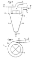
- the cyclone comprises: an inlet spiral with an acceleration nozzle; a cylindrical separation body; a cone for receiving the liquid-wet particle mixture; and a central chimney for the outlet of the gaseous fluid; said central chimney of the cyclone can be provided with an anti-rotation means.
- the installation 1, preferably mobile, for pumping a liquid or gaseous fluid, such as in particular air, charged with solid particles, or possibly liquids such as spray, comprises at least one reservoir 2 for collecting the liquid fraction and / or the heaviest solid particles dispersed in the gaseous fluid, the reservoir 2 comprising at least one fluid inlet 3 and being connected to one end of at least one pipe 4, the other end of which is connected to means 5 for evacuating the tank 2; the end of the pipe 4 connected to the tank 2 can be provided with a filling stop device (float).
- float filling stop device
- Such a pumping installation can be mounted on a vehicle (not shown), in particular a truck trailer, and is thus easily movable from one work site to another.
- a liquid ring pump As means 5 for creating the vacuum in the tank 2, one can use, for example, a liquid ring pump, or a vane pump.
- the pumping installation 1 is particularly remarkable in that it comprises a device 6 for trapping the lightest particles entrained by the flow of gaseous fluid in the pipe 4, said device 6 being connected to the pipe 4 between the tank 2 and the means 5 for creating a vacuum, and extracting the light particles from the pipe 4.
- the device 6 for trapping light particles comprises at least one means forming a cyclone 7 and, as illustrated, means 8 for wetting the lighter solid particles, for example by injecting water into the flow of gaseous fluid, provided upstream of cyclone 7.
- the device 6 for trapping the particles comprises a tank 9, connected to the outlet of the cyclone 7 by an evacuation pipe 10, the tank 9 collecting the liquid mixture (in particular water) - particles, mixture which forms a mud which will settle at the bottom of the tank.
- the liquid mixture in particular water
- the means 8 for wetting the particles comprise at least one pump 11 connected, downstream, by a pipe 12 to the pipe 4, connecting the main tank 2 and the pump 5, in the vicinity of the inlet of the cyclone 7 and, upstream , preferably to the tank 9 previously partially filled with wetting liquid, in particular water, and this by means of a pipe 13.
- the pipes 12 and 13 are provided with valves 14 and 15, respectively.
- the pump 11 can be connected, on the one hand upstream, to the bottom of the tank 9 by a pipe 16 and, on the other hand, downstream, to the collection tank 2 by a pipe 17; the lines 16 and 17 being provided with valves 18 and 19, respectively.
- the cyclone 7, used in the installation of the invention comprises an inlet spiral 21 with acceleration nozzle 22; a cylindrical separation body 23; a cone 24 for receiving the liquid-wet particles mixture and a central chimney 25 for the outlet of the gaseous fluid; the central chimney 25 of the cyclone being provided with an anti-rotation cross 26.
- the pumping installation according to the invention operates in the following manner.
- the pump 5 creates a vacuum in the tank 2.
- the pressure difference between the inside and the outside of the tank causes the transfer of the fluid from the outside to the inside of the tank at very high speed.
- the vacuum is maintained at the pressure near the saturation vapor pressure of the liquid, at a given temperature. If the liquid is transported in emulsion with air, it is necessary to separate the air from the liquid; this is essentially done in the tank. To obtain this separation, or plays, at the same time, on the difference in density of the air and of the pumped liquid, the speed of entry into the tank, and the speed of return of the air at the exit of the tank.
- the filling takes place in the vicinity of the rear bottom of the tank, and the fluid inlet pipe 3 extends, inside the tank 2, towards the front of the latter and upwards; the air is pumped upstream of this pipe 3.
- the speed of penetration into the tank is such that all the dense particles are thrown forward and trapped in the tank, while the return passage of the air takes place through a very large section, and therefore at low speed; this low speed preventing the suspension of dense particles.
- the maximum filling of the tank is calculated as a function of the free space necessary for the return of air at low speed, that is to say approximately ten times the cross section of the filling pipe.
- An automatic level (not shown) can be provided, which, depending on the maximum level chosen, will stop the installation; a switching system allowing to play on the maximum level in the tank.
- the device 6 To trap these particles and extract them from the flow of gaseous fluid circulating in the pipe 4, the device 6 according to the invention is used, comprising, in particular, the cyclone 7 and the means 8 for wetting the light particles which makes it possible to weigh down those here, so as to facilitate their extraction from the flow of gaseous fluid by the cyclone.
- the tank 9 is filled with water to a given volume, the free volume corresponding to the storage volume of the sludge formed by the mixture of light solid particles-water.
- the pump 11 sucks the water in the tank 9, about halfway up, and delivers it into the pipe 12 at the inlet of the cyclone 7.
- the inlet of the cyclone 7 comprises an acceleration nozzle 22 so as to, d on the one hand, create an intimate air-water-dust mixture due to the atomization of the water obtained by the high speed of the air in cyclone 7, and, on the other hand, create in the cyclone a maximum rate of turn to obtain air-water centrifugation.
- the discharge pipe 10 of the cyclone 7 can be connected to the dome of the tank, or, as in the embodiment shown, the discharge can be provided so as to immerse in the volume of water, a pipe 20 d pressure balancing then being necessary between the surface of the water body and the interior of the cyclone.
- the pump 11 can be connected, both to the bottom of the tank 9 and to the main tank 2 so as to allow the transfer of the sludge from the tank 9 to the collection tank 2.
- An automatic cleaning device can optionally be implemented. This device will be operational during the entire operating time.
- the cyclone makes it possible to capture the spray, these being transferred to the collection tank once the maximum tolerable level reached in the auxiliary tank 9.
- the vacuum pump does not more risk of entraining other fluids than gaseous fluids towards the vacuum pump.
Landscapes
- Chemical & Material Sciences (AREA)
- Chemical Kinetics & Catalysis (AREA)
- Engineering & Computer Science (AREA)
- Mechanical Engineering (AREA)
- General Engineering & Computer Science (AREA)
- Cyclones (AREA)
- Treatment Of Sludge (AREA)
- Jet Pumps And Other Pumps (AREA)
Abstract
Description
La présente invention concerne une installation, de préférence mobile, de pompage d'un fluide liquide ou gazeux, tel que notamment de l'air, chargé de particules solides ou liquides.The present invention relates to an installation, preferably mobile, for pumping a liquid or gaseous fluid, such as in particular air, charged with solid or liquid particles.
De manière usuelle, pour pomper, d'une part, des liquides, qui peuvent être divers effluents provenant de l'industrie, et, d'autre part, des fluides gazeux, tels que de l'air chargé de poussières de charbon par exemple, on utilise des installations, de préférence mobiles, spécialement adaptées pour chacun desdits usages. En dehors du problème lié à l'encrassement de l'appareillage, notamment des moyens de pompage, par les poussières les plus fines dispersées dans le fluide pompé, pour un même site de travail, au moins deux véhicules sont nécessaires, chacun étant prévu pour un type de pompage particulier. On a donc imaginé de prévoir une installation qui peut à la fois pomper des liquides et des fluides gazeux. Pour chaque site de travail, il n'est plus nécessaire d'utiliser qu'un seul véhicule polyvalent. Néanmoins, il est bien évident qu'également dans ce cas, le problème de l'encrassement de l'appareillage par les poussières les plus fines demeure.Usually, to pump, on the one hand, liquids, which can be various effluents from industry, and, on the other hand, gaseous fluids, such as air charged with coal dust for example , preferably mobile installations are used which are specially adapted for each of said uses. Apart from the problem linked to the fouling of the equipment, in particular pumping means, by the finest dust dispersed in the pumped fluid, for the same work site, at least two vehicles are necessary, each being provided for a particular type of pumping. It has therefore been imagined to provide an installation which can both pump liquids and gaseous fluids. Only one multipurpose vehicle is needed for each work site. Nevertheless, it is quite obvious that also in this case, the problem of fouling of the apparatus by the finest dust remains.
La présente invention a donc pour but de résoudre ce problème en procurant une installation, de préférence mobile, de pompage d'un fluide liquide ou gazeux, tel que notamment de l'air, chargé de particules, dans laquelle, en particulier les plus fines poussières ne sont plus susceptibles d'affecter le fonctionnement de l'installation.The present invention therefore aims to solve this problem by providing an installation, preferably mobile, for pumping a liquid or gaseous fluid, such as in particular air, charged with particles, in which, in particular the finest dust is no longer likely to affect the operation of the installation.
A cet effet, selon l'invention, l'installation, de préférence mobile, de pompage d'un fluide liquide ou gazeux, tel que notamment de l'air, chargé de particules solides ou liquides, du type comprenant au moins un réservoir de collecte de la fraction liquide et/ou des particules solides les plus lourdes dispersées dans le fluide gazeux, réservoir comportant au moins une entrée de fluide et étant relié à une extrémité d'au moins une conduite dont l'autre extrémité est connectée à des moyens pour faire le vide dans ledit réservoir, est notamment remarquable en ce qu'elle comporte de plus un dispositif pour piéger les particules les plus légères entraînées par le flux de fluide gazeux dans la conduite, ledit dispositif étant branché sur ladite conduite entre le réservoir et les moyens de création de vide, et extrayant lesdites particules de la conduite.To this end, according to the invention, the installation, preferably mobile, for pumping a liquid or gaseous fluid, such as in particular air, charged with solid or liquid particles, of the type comprising at least one reservoir for collection of the liquid fraction and / or heavier solid particles dispersed in the gaseous fluid, reservoir comprising at least one fluid inlet and being connected to one end of at least one pipe, the other end of which is connected to means for creating a vacuum in said reservoir, is notably remarkable in that it further comprises a device for trapping the lightest particles entrained by the flow of gaseous fluid in the pipe, said device being connected to said pipe between the reservoir and the means for creating vacuum, and extracting said particles from the pipe.
Une telle installation permet donc d'éviter que les particules, notamment solides les plus légères n'atteignent les parties fragiles de l'appareillage, notamment les moyens de pompage, en risquant de les encrasser et de nuire ainsi au bon fonctionnement de l'installation.Such an installation therefore makes it possible to prevent the particles, in particular the lighter solids from reaching the fragile parts of the apparatus, in particular the pumping means, risking fouling them and thus adversely affecting the proper functioning of the installation. .
Selon une autre caractéristique de l'invention, le dispositif de piégeage des particules légères comporte au moins un moyen formant cyclone.According to another characteristic of the invention, the device for trapping light particles comprises at least one means forming a cyclone.
Selon encore une autre caractéristique de l'invention, on prévoit, en amont du moyen formant cyclone, des moyens de mouillage des particules solides les plus légères, par exemple par injection d'eau dans le flux de fluide gazeux.According to yet another characteristic of the invention, means are provided, upstream of the cyclone-forming means, for wetting the lightest solid particles, for example by injecting water into the flow of gaseous fluid.
Selon une autre caractéristique de l'invention, le dispositif de piégeage des particules comporte de plus une cuve, reliée à la sortie du cyclone, pour recueillir le mélange liquide (notamment de l'eau) - particules.According to another characteristic of the invention, the particle trapping device further comprises a tank, connected to the outlet of the cyclone, for collecting the liquid mixture (in particular water) - particles.
Selon encore une autre caractéristique de l'invention, les moyens de mouillage des particules comprennent au moins une pompe reliée, en aval, à la conduite précitée au voisinage de l'entrée du cyclone et, en amont, de préférence à ladite cuve préalablement partiellement remplie de liquide de mouillage, notamment de l'eau.According to yet another characteristic of the invention, the means for wetting the particles comprise at least one pump connected, downstream, to the aforementioned pipe in the vicinity of the inlet of the cyclone and, upstream, preferably to said tank previously partially filled with wetting liquid, especially water.
Selon encore une autre caractéristique de l'invention, la pompe précitée peut être reliée, d'une part en amont, au fond de la cuve précitée et, d'autre part, en aval, au réservoir principal de collecte.According to yet another characteristic of the invention, the aforementioned pump can be connected, on the one hand upstream, to the bottom of the aforementioned tank and, on the other hand, downstream, to the main collection tank.
On peut prévoir, en outre, une conduite d'équilibrage de pression entre la surface de liquide dans la cuve et le cyclone.It is also possible to provide a pressure equalization pipe between the liquid surface in the tank and the cyclone.
Selon encore une autre caractéristique de l'invention, le cyclone comprend : une spirale d'entrée avec tuyère d'accélération ; un corps cylindrique de séparation ; un cône récepteur du mélange liquide-particules mouillées ; et une cheminée centrale de sortie du fluide gazeux ; ladite cheminée centrale du cyclone pouvant être munie d'un moyen d'antigiration.According to yet another characteristic of the invention, the cyclone comprises: an inlet spiral with an acceleration nozzle; a cylindrical separation body; a cone for receiving the liquid-wet particle mixture; and a central chimney for the outlet of the gaseous fluid; said central chimney of the cyclone can be provided with an anti-rotation means.
L'invention sera mieux comprise, et d'autres détails, caractéristiques et avantages de celle-ci apparaîtront plus clairement à la lumière de la description explicative qui va suivre d'un mode de réalisation actuellement préféré de l'invention, description faite en référence aux dessins schématiques annexés, dans lesquels :
- - la figure 1 est une vue d'ensemble schématique, partiellement en coupe, de l'installation de pompage de l'invention ;
- - la figure 2 est une vue en coupe schématique du cyclone utilisé dans l'installation de l'invention ; et
- - la figure 3 est une vue en coupe schématique selon la ligne III-III de la figure 2.
- - Figure 1 is a schematic overview, partially in section, of the pumping installation of the invention;
- - Figure 2 is a schematic sectional view of the cyclone used in the installation of the invention; and
- - Figure 3 is a schematic sectional view along line III-III of Figure 2.
En se référant en particulier à la figure 1, l'installation 1, de préférence mobile, de pompage d'un fluide liquide ou gazeux, tel que notamment de l'air, chargé de particules solides, ou éventuellement liquides tels que des embruns, comprend au moins un réservoir de collecte 2 de la fraction liquide et/ou des particules solides les plus lourdes dispersées dans le fluide gazeux, le réservoir 2 comportant au moins une entrée 3 de fluide et étant reliée à une extrémité d'au moins une conduite 4 dont l'autre extrémité est connectée à des moyens 5 pour faire le vide dans le réservoir 2 ; l'extrémité de la conduite 4 reliée au réservoir 2 pouvant être munie d'un dispositif d'arrêt au remplissage (flotteur).Referring in particular to FIG. 1, the
Une telle installation de pompage peut être montée sur un véhicule (non représenté), notamment une remorque de camion, et est ainsi facilement déplaçable d'un site de travail à un autre.Such a pumping installation can be mounted on a vehicle (not shown), in particular a truck trailer, and is thus easily movable from one work site to another.
Comme moyens 5 pour créer le vide dans le réservoir 2, on peut utiliser, par exemple, une pompe à anneau liquide, ou une pompe à palettes.As means 5 for creating the vacuum in the
L'installation 1 de pompage, selon l'invention, est notamment remarquable en ce qu'elle comporte un dispositif 6 pour piéger les particules les plus légères entraînées par le flux de fluide gazeux dans la conduite 4, ledit dispositif 6 étant branché sur la conduite 4 entre le réservoir 2 et les moyens 5 de création de vide, et extrayant les particules légères de la conduite 4.The
Le dispositif 6 de piégeage des particules légères comporte au moins un moyen formant cyclone 7 et, comme cela est illustré, des moyens 8 de mouillage des particules solides les plus légères, par exemple par injection d'eau dans le flux de fluide gazeux, prévus en amont du cyclone 7.The device 6 for trapping light particles comprises at least one means forming a cyclone 7 and, as illustrated, means 8 for wetting the lighter solid particles, for example by injecting water into the flow of gaseous fluid, provided upstream of cyclone 7.
En outre, le dispositif 6 de piégeage des particules comporte une cuve 9, reliée à la sortie du cyclone 7 par une canalisation d'évacuation 10, la cuve 9 recueillant le mélange liquide (notamment de l'eau) - particules, mélange qui forme une boue qui va se déposer au fond de la cuve.In addition, the device 6 for trapping the particles comprises a
Les moyens 8 de mouillage des particules comprennent au moins une pompe 11 reliée, en aval, par une conduite 12 à la conduite 4, reliant le réservoir principal 2 et la pompe 5, au voisinage de l'entrée du cyclone 7 et, en amont, de préférence à la cuve 9 préalablement partiellement remplie de liquide de mouillage, notamment de l'eau, et cela par l'intermédiaire d'une conduite 13. Les conduites 12 et 13 sont munies de vannes 14 et 15, respectivement.The
De plus, la pompe 11 peut être reliée, d'une part en amont, au fond de la cuve 9 par une conduite 16 et, d'autre part, en aval, au réservoir 2 de collecte par une conduite 17 ; les conduites 16 et 17 étant munies de vannes 18 et 19, respectivement.In addition, the pump 11 can be connected, on the one hand upstream, to the bottom of the
Enfin, on prévoit, dans l'installation, une conduite 20 d'équilibrage de pression entre la surface de liquide dans la cuve 9 et le cyclone 7.Finally, provision is made in the installation for a
En se référant maintenant plus particulièrement aux figures 2 et 3, le cyclone 7, utilisé dans l'installation de l'invention, comprend une spirale d'entrée 21 avec tuyère d'accélération 22 ; un corps cylindrique de séparation 23 ; une cône 24 pour la réception du mélange liquide-particules mouillées et une cheminée centrale 25 de sortie du fluide gazeux ; la cheminée centrale 25 du cyclone étant munie d'une croix d'antigiration 26.Referring now more particularly to Figures 2 and 3, the cyclone 7, used in the installation of the invention, comprises an
L'installation de pompage, selon l'invention, fonctionne de la manière suivante.The pumping installation according to the invention operates in the following manner.
La pompe 5 crée le vide dans le réservoir 2. La différence de pression entre l'intérieur et l'extérieur du réservoir entraîne le transfert du fluide de l'extérieur vers l'intérieur du réservoir à très grande vitesse.The pump 5 creates a vacuum in the
Si le fluide est liquide, le vide est maintenu à la pression près de la tension de la vapeur saturante du liquide, à une température donnée. Si le liquide est transporté en émulsion avec de l'air, il faut séparer l'air du liquide ; cela se faisant essentiellement dans le réservoir. Pour obtenir cette séparation, ou joue, à la fois, sur la différence de densité de l'air et du liquide pompés, la vitesse d'entrée dans le réservoir, et la vitesse de retour de l'air à la sortie du réservoir.If the fluid is liquid, the vacuum is maintained at the pressure near the saturation vapor pressure of the liquid, at a given temperature. If the liquid is transported in emulsion with air, it is necessary to separate the air from the liquid; this is essentially done in the tank. To obtain this separation, or plays, at the same time, on the difference in density of the air and of the pumped liquid, the speed of entry into the tank, and the speed of return of the air at the exit of the tank.
Le remplissage s'effectue au voisinage du fond arrière du réservoir, et la conduite 3 d'entrée de fluide s'étend, à l'intérieur du réservoir 2, vers l'avant de ce dernier et vers le haut ; le pompage de l'air s'effectuant en amont de cette conduite 3.The filling takes place in the vicinity of the rear bottom of the tank, and the
La vitesse de pénétration dans le réservoir est telle que toutes les particules denses sont projetées vers l'avant et piégées dans le réservoir, tandis que le passage retour de l'air se fait par une très grande section, et donc à faible vitesse ; cette faible vitesse interdisant le maintien en suspension des particules denses.The speed of penetration into the tank is such that all the dense particles are thrown forward and trapped in the tank, while the return passage of the air takes place through a very large section, and therefore at low speed; this low speed preventing the suspension of dense particles.
On doit noter que le remplissage maximum du réservoir est calculé en fonction de l'espace libre nécessaire au retour de l'air à faible vitesse, c'est-à-dire environ dix fois la section de la conduite de remplissage. On peut prévoir un niveau automatique (non représenté), qui, en fonction du niveau maximum choisi, arrêtera l'installation ; un système de commutation permettant de jouer sur le niveau maximum dans le réservoir.It should be noted that the maximum filling of the tank is calculated as a function of the free space necessary for the return of air at low speed, that is to say approximately ten times the cross section of the filling pipe. An automatic level (not shown) can be provided, which, depending on the maximum level chosen, will stop the installation; a switching system allowing to play on the maximum level in the tank.
Dans le cas où l'on a à pomper un fluide gazeux chargé de particules solides, par exemple des poussières de charbon, il est bien entendu que le principe général de remplissage du réservoir est conservé de sorte qu'il y a séparation de l'air et des poussières denses dans le réservoir. Seules, les poussières les plus légères restent en suspension dans l'air et s'échappent du réservoir.In the case where one has to pump a gaseous fluid charged with solid particles, for example coal dust, it is understood that the general principle of filling the tank is preserved so that there is separation of the dense air and dust in the tank. Only the lightest dust remains suspended in the air and escapes from the tank.
Pour piéger ces particules et les extraire du flux de fluide gazeux circulant dans la conduite 4, on utilise le dispositif 6 selon l'invention, comportant, notamment, le cyclone 7 et les moyens 8 de mouillage des particules légères qui permet d'alourdir celles-ci, de façon à faciliter leur extraction du flux de fluide gazeux par le cyclone.To trap these particles and extract them from the flow of gaseous fluid circulating in the
En fonctionnement, la cuve 9 est remplie d'eau jusqu'à un volume donné, le volume libre correspondant au volume de stockage des boues formées par le mélange particules solides légères-eau. La pompe 11 aspire l'eau dans la cuve 9, environ à mi-hauteur, et refoule dans la canalisation 12 à l'entrée du cyclone 7. L'entrée du cyclone 7 comporte une tuyère 22 d'accélération de manière à, d'une part, créer un mélange intime air-eau-poussière du fait de l'atomisation de l'eau obtenue par la vitesse importante de l'air dans le cyclone 7, et, d'autre part, créer dans le cyclone une vitesse de giration maximale pour obtenir la centrifugation air-eau.In operation, the
On peut donc calculer les paramètres du cyclone de façon à obtenir une vitesse de giration maximale, une descente d'air à très faible vitesse dans le corps cylindrique du cyclone, et une remontée d'air dans la cheminée centrale à très faible vitesse, afin d'éviter d'entraîner des gouttelettes d'eau.We can therefore calculate the parameters of the cyclone so as to obtain a maximum rate of gyration, a descent of air at very low speed into the cylindrical body of the cyclone, and an ascent of air in the central chimney at very low speed, in order avoid entraining water droplets.
La conduite d'évacuation 10 du cyclone 7 peut être branchée sur le dôme de la cuve, ou, comme dans le mode de réalisation représenté, l'évacuation peut être prévue de manière à plonger dans le volume d'eau, une conduite 20 d'équilibrage de pression étant alors nécessaire entre la surface du plan d'eau et l'intérieur du cyclone.The
D'autre part, afin de procurer une plus grande autonomie à l'installation, la pompe 11 peut être reliée, à la fois, au fond de la cuve 9 et au réservoir principal 2 de façon à permettre le transfert des boues de la cuve 9 au réservoir 2 de collecte. Un dispositif de curage automatique peut éventuellement être mis en place. Ce dispositif sera opérationnel pendant tout le temps de fonctionnement.On the other hand, in order to provide greater autonomy to the installation, the pump 11 can be connected, both to the bottom of the
On notera enfin que, dans le cas du pompage d'un liquide, le cyclone permet de capter les embruns, ceux-ci étant transférés dans le réservoir de collecte une fois le niveau maximum tolérable atteint dans la cuve auxiliaire 9. Ainsi, on ne risque plus d'entraîner vers la pompe à vide d'autres fluides que des fluides gazeux.Finally, it will be noted that, in the case of pumping a liquid, the cyclone makes it possible to capture the spray, these being transferred to the collection tank once the maximum tolerable level reached in the
Claims (10)
caractérisée par une conduite (20) d'équilibrage de pression entre la surface de liquide dans la cuve (9) et le cyclone (7).7 - Installation according to any one of claims 4 to 6,
characterized by a pressure equalization line (20) between the liquid surface in the tank (9) and the cyclone (7).
caractérisée en ce que le cyclone (7) comprend : une spirale d'entrée (21) avec tuyère d'accélération (22) ; un corps cylindrique de séparation (23) ; un cône (24) récepteur du mélange liquide-particules mouillées, et une cheminée centrale (25) de sortie de fluide gazeux.8 - Installation according to any one of claims 2 to 7,
characterized in that the cyclone (7) comprises: an inlet spiral (21) with an acceleration nozzle (22); a cylindrical separation body (23); a cone (24) receiving the liquid-wet particles mixture, and a central chimney (25) for the outlet of gaseous fluid.
caractérisé en ce qu'il est équipé d'une installation selon l'une quelconque des revendications 1 à 9.10 - Vehicle,
characterized in that it is equipped with an installation according to any one of claims 1 to 9.
Priority Applications (4)
| Application Number | Priority Date | Filing Date | Title |
|---|---|---|---|
| FR858515108A FR2591675B1 (en) | 1985-10-11 | 1985-10-11 | PUMPING SYSTEM FOR A PARTICLE-LOADED FLUID, AND VEHICLE PROVIDED WITH SAID SYSTEM |
| EP87400643A EP0283625B1 (en) | 1987-03-23 | 1987-03-23 | Installation for aspiration of a particle-charged fluid, and vehicle equipped with this installation |
| DE8787400643T DE3774118D1 (en) | 1987-03-23 | 1987-03-23 | DEVICE FOR SUCTIONING A PARTICLE-LOADED FLUID AND A VEHICLE EQUIPPED WITH THIS DEVICE. |
| AT87400643T ATE68717T1 (en) | 1987-03-23 | 1987-03-23 | DEVICE FOR SUCTION OF PARTICLE-LOADED FLUID AND VEHICLE EQUIPPED WITH SUCH DEVICE. |
Applications Claiming Priority (1)
| Application Number | Priority Date | Filing Date | Title |
|---|---|---|---|
| EP87400643A EP0283625B1 (en) | 1987-03-23 | 1987-03-23 | Installation for aspiration of a particle-charged fluid, and vehicle equipped with this installation |
Publications (2)
| Publication Number | Publication Date |
|---|---|
| EP0283625A1 true EP0283625A1 (en) | 1988-09-28 |
| EP0283625B1 EP0283625B1 (en) | 1991-10-23 |
Family
ID=8198194
Family Applications (1)
| Application Number | Title | Priority Date | Filing Date |
|---|---|---|---|
| EP87400643A Expired - Lifetime EP0283625B1 (en) | 1985-10-11 | 1987-03-23 | Installation for aspiration of a particle-charged fluid, and vehicle equipped with this installation |
Country Status (4)
| Country | Link |
|---|---|
| EP (1) | EP0283625B1 (en) |
| AT (1) | ATE68717T1 (en) |
| DE (1) | DE3774118D1 (en) |
| FR (1) | FR2591675B1 (en) |
Cited By (1)
| Publication number | Priority date | Publication date | Assignee | Title |
|---|---|---|---|---|
| WO2015022458A1 (en) * | 2013-08-14 | 2015-02-19 | Ortec Expansion | Process and unit for pumping flammable products capable of forming an explosive atmosphere |
Families Citing this family (2)
| Publication number | Priority date | Publication date | Assignee | Title |
|---|---|---|---|---|
| FR2673861B1 (en) * | 1991-03-11 | 1995-03-03 | Gb 2000 International | CENTRALIZED VACUUM CLEANING INSTALLATION. |
| US11794138B2 (en) * | 2020-10-19 | 2023-10-24 | Sierra Space Corporation | Microgravity system phase separator |
Citations (5)
| Publication number | Priority date | Publication date | Assignee | Title |
|---|---|---|---|---|
| US1544981A (en) * | 1924-09-30 | 1925-07-07 | Hasse Frank Clarence | Dust and dirt collector |
| DE2256678A1 (en) * | 1972-11-18 | 1974-05-22 | Koerting Ag | Centrifugal separator for gas contaminants - by removing liqs. and solids in gas edge layer and recirculating to give clean exit gas stream |
| US4065527A (en) * | 1976-02-19 | 1977-12-27 | Graber David A | Method and apparatus for interaction of gas and liquid |
| US4218226A (en) * | 1978-07-25 | 1980-08-19 | Link Built Products of Ocala, Inc. | Vacuum apparatus |
| DE3224270A1 (en) * | 1981-06-29 | 1983-01-13 | Hamworthy Engineering Ltd., Poole, Dorset | Apparatus for the purification of gases |
-
1985
- 1985-10-11 FR FR858515108A patent/FR2591675B1/en not_active Expired - Lifetime
-
1987
- 1987-03-23 DE DE8787400643T patent/DE3774118D1/en not_active Expired - Lifetime
- 1987-03-23 AT AT87400643T patent/ATE68717T1/en not_active IP Right Cessation
- 1987-03-23 EP EP87400643A patent/EP0283625B1/en not_active Expired - Lifetime
Patent Citations (5)
| Publication number | Priority date | Publication date | Assignee | Title |
|---|---|---|---|---|
| US1544981A (en) * | 1924-09-30 | 1925-07-07 | Hasse Frank Clarence | Dust and dirt collector |
| DE2256678A1 (en) * | 1972-11-18 | 1974-05-22 | Koerting Ag | Centrifugal separator for gas contaminants - by removing liqs. and solids in gas edge layer and recirculating to give clean exit gas stream |
| US4065527A (en) * | 1976-02-19 | 1977-12-27 | Graber David A | Method and apparatus for interaction of gas and liquid |
| US4218226A (en) * | 1978-07-25 | 1980-08-19 | Link Built Products of Ocala, Inc. | Vacuum apparatus |
| DE3224270A1 (en) * | 1981-06-29 | 1983-01-13 | Hamworthy Engineering Ltd., Poole, Dorset | Apparatus for the purification of gases |
Cited By (2)
| Publication number | Priority date | Publication date | Assignee | Title |
|---|---|---|---|---|
| WO2015022458A1 (en) * | 2013-08-14 | 2015-02-19 | Ortec Expansion | Process and unit for pumping flammable products capable of forming an explosive atmosphere |
| FR3009742A1 (en) * | 2013-08-14 | 2015-02-20 | Ortec Expansion | METHOD AND UNIT FOR PUMPING FLAMMABLE PRODUCTS LIKELY TO FORM AN EXPLOSIVE ATMOSPHERE |
Also Published As
| Publication number | Publication date |
|---|---|
| FR2591675A1 (en) | 1987-06-19 |
| ATE68717T1 (en) | 1991-11-15 |
| EP0283625B1 (en) | 1991-10-23 |
| DE3774118D1 (en) | 1991-11-28 |
| FR2591675B1 (en) | 1992-05-22 |
Similar Documents
| Publication | Publication Date | Title |
|---|---|---|
| FR2578170A1 (en) | SEPARATOR FOR SEPARATING A GAS FROM A LIQUID. | |
| FR2499122A1 (en) | DREDGING DEVICE | |
| FR2752416A1 (en) | DEVICE AND METHOD FOR RECOVERING PETROL VAPORS USING OXYGEN DETECTION | |
| WO2007141448A1 (en) | Liqiud-gas mixing device | |
| FR2505680A1 (en) | APPARATUS AND METHOD FOR THE CONCENTRATION OF SLUDGE | |
| FR2480402A1 (en) | IMPROVEMENTS IN OR RELATING TO FLUID PRESSURE DISSIPATION APPARATUSES | |
| EP0283625B1 (en) | Installation for aspiration of a particle-charged fluid, and vehicle equipped with this installation | |
| FR2604639A1 (en) | DEGREASER FOR SEPARATING GASES OR VAPORS, EXCLUDING LIQUID / GAS OR LIQUIDS / VAPORS IN PIPES | |
| FR2864169A1 (en) | Fuel filter assembly for motor vehicle, has water outlet duct connected to fuel filtering module, positioned inside reservoir, within location that is accessible from outside reservoir, for draining water to filtering module | |
| FR2726203A1 (en) | Treatment of aqueous effluents in a centripetal flotation separator | |
| EP0469977A1 (en) | Vacuum sanitary installation having a gaseous fluid cleaner | |
| CA2304402C (en) | Installation of liquid hydrocarbons equipped with a means of vapour recovery | |
| EP0296917B1 (en) | Device for continuously circulating a liquid in order to sample or to check this liquid | |
| FR2790255A1 (en) | SYSTEM AND METHOD FOR DETECTING, BY A DENSITY DETECTOR, THE RECOVERY OF VAPOR RECOVERED ON BOARD VEHICLES | |
| FR2829703A1 (en) | Diesel fuel water separator contains two-sided thermoplastic grille of specified pore size | |
| FR2818203A1 (en) | AIR RELEASE AND / OR PRESSURE COMPENSATION SYSTEM FOR A FUEL CONTAINER | |
| EP4006340A1 (en) | Device and method for pumping products with low vacuum evaporation | |
| FR2809179A1 (en) | Self-priming system for gas or liquid extraction from wells, includes separator with liquid ring pump pulling vacuum, with pump extracting liquid | |
| FR3109894A1 (en) | Particle collection device and vehicle equipped with such a device | |
| FR2474328A1 (en) | Sepn. tank for immiscible liquids with different densities - used esp. for continuous sepn. of oil from waste water, where water outlet can be closed for periodic removal of oil | |
| EP1500419B1 (en) | Automatic obturator for a vessel for separating light liquids such as hydrocarbons | |
| WO2003006296A1 (en) | Hydraulic braking circuit with filtration means | |
| EP0648523B1 (en) | Device and process for degasing a hydraulic circuit | |
| FR2711072A1 (en) | Vertical separator-clarifier with a cleanable lamellar cell intended for water treatment | |
| EP0344063A1 (en) | Degassing device for the fuel feeding of an internal combustion engine |
Legal Events
| Date | Code | Title | Description |
|---|---|---|---|
| PUAI | Public reference made under article 153(3) epc to a published international application that has entered the european phase |
Free format text: ORIGINAL CODE: 0009012 |
|
| AK | Designated contracting states |
Kind code of ref document: A1 Designated state(s): AT BE CH DE ES GB GR IT LI LU NL SE |
|
| 17P | Request for examination filed |
Effective date: 19881024 |
|
| 17Q | First examination report despatched |
Effective date: 19900612 |
|
| GRAA | (expected) grant |
Free format text: ORIGINAL CODE: 0009210 |
|
| AK | Designated contracting states |
Kind code of ref document: B1 Designated state(s): AT BE CH DE ES GB GR IT LI LU NL SE |
|
| PG25 | Lapsed in a contracting state [announced via postgrant information from national office to epo] |
Ref country code: SE Effective date: 19911023 Ref country code: NL Effective date: 19911023 Ref country code: GR Free format text: LAPSE BECAUSE OF FAILURE TO SUBMIT A TRANSLATION OF THE DESCRIPTION OR TO PAY THE FEE WITHIN THE PRESCRIBED TIME-LIMIT Effective date: 19911023 Ref country code: AT Effective date: 19911023 |
|
| REF | Corresponds to: |
Ref document number: 68717 Country of ref document: AT Date of ref document: 19911115 Kind code of ref document: T |
|
| REF | Corresponds to: |
Ref document number: 3774118 Country of ref document: DE Date of ref document: 19911128 |
|
| GBT | Gb: translation of ep patent filed (gb section 77(6)(a)/1977) | ||
| ITF | It: translation for a ep patent filed |
Owner name: MODIANO & ASSOCIATI S.R.L. |
|
| PG25 | Lapsed in a contracting state [announced via postgrant information from national office to epo] |
Ref country code: ES Free format text: LAPSE BECAUSE OF FAILURE TO SUBMIT A TRANSLATION OF THE DESCRIPTION OR TO PAY THE FEE WITHIN THE PRESCRIBED TIME-LIMIT Effective date: 19920203 |
|
| NLV1 | Nl: lapsed or annulled due to failure to fulfill the requirements of art. 29p and 29m of the patents act | ||
| PG25 | Lapsed in a contracting state [announced via postgrant information from national office to epo] |
Ref country code: LU Free format text: LAPSE BECAUSE OF NON-PAYMENT OF DUE FEES Effective date: 19920331 Ref country code: LI Effective date: 19920331 Ref country code: CH Effective date: 19920331 Ref country code: BE Effective date: 19920331 |
|
| PLBE | No opposition filed within time limit |
Free format text: ORIGINAL CODE: 0009261 |
|
| STAA | Information on the status of an ep patent application or granted ep patent |
Free format text: STATUS: NO OPPOSITION FILED WITHIN TIME LIMIT |
|
| BERE | Be: lapsed |
Owner name: ETS. RIVARD S.A. Effective date: 19920331 |
|
| 26N | No opposition filed | ||
| REG | Reference to a national code |
Ref country code: CH Ref legal event code: PL |
|
| PGFP | Annual fee paid to national office [announced via postgrant information from national office to epo] |
Ref country code: GB Payment date: 19950314 Year of fee payment: 9 |
|
| PGFP | Annual fee paid to national office [announced via postgrant information from national office to epo] |
Ref country code: DE Payment date: 19950410 Year of fee payment: 9 |
|
| PG25 | Lapsed in a contracting state [announced via postgrant information from national office to epo] |
Ref country code: GB Effective date: 19960323 |
|
| GBPC | Gb: european patent ceased through non-payment of renewal fee |
Effective date: 19960323 |
|
| PG25 | Lapsed in a contracting state [announced via postgrant information from national office to epo] |
Ref country code: DE Effective date: 19961203 |
|
| PG25 | Lapsed in a contracting state [announced via postgrant information from national office to epo] |
Ref country code: IT Free format text: LAPSE BECAUSE OF NON-PAYMENT OF DUE FEES;WARNING: LAPSES OF ITALIAN PATENTS WITH EFFECTIVE DATE BEFORE 2007 MAY HAVE OCCURRED AT ANY TIME BEFORE 2007. THE CORRECT EFFECTIVE DATE MAY BE DIFFERENT FROM THE ONE RECORDED. Effective date: 20050323 |