EP0283625A1 - Einrichtung zum Absaugen eines partikelbeladenen Fluids und ein mit dieser Einrichtung ausgerüstetes Fahrzeug - Google Patents
Einrichtung zum Absaugen eines partikelbeladenen Fluids und ein mit dieser Einrichtung ausgerüstetes Fahrzeug Download PDFInfo
- Publication number
- EP0283625A1 EP0283625A1 EP87400643A EP87400643A EP0283625A1 EP 0283625 A1 EP0283625 A1 EP 0283625A1 EP 87400643 A EP87400643 A EP 87400643A EP 87400643 A EP87400643 A EP 87400643A EP 0283625 A1 EP0283625 A1 EP 0283625A1
- Authority
- EP
- European Patent Office
- Prior art keywords
- particles
- cyclone
- tank
- liquid
- installation according
- Prior art date
- Legal status (The legal status is an assumption and is not a legal conclusion. Google has not performed a legal analysis and makes no representation as to the accuracy of the status listed.)
- Granted
Links
- 239000012530 fluid Substances 0.000 title claims abstract description 38
- 238000009434 installation Methods 0.000 title claims abstract description 33
- 239000002245 particle Substances 0.000 claims abstract description 42
- 239000007788 liquid Substances 0.000 claims abstract description 33
- 238000005086 pumping Methods 0.000 claims abstract description 15
- 239000007787 solid Substances 0.000 claims abstract description 13
- XLYOFNOQVPJJNP-UHFFFAOYSA-N water Substances O XLYOFNOQVPJJNP-UHFFFAOYSA-N 0.000 claims description 17
- 238000011144 upstream manufacturing Methods 0.000 claims description 10
- 238000009736 wetting Methods 0.000 claims description 10
- 239000000203 mixture Substances 0.000 claims description 9
- 238000000926 separation method Methods 0.000 claims description 5
- 230000001133 acceleration Effects 0.000 claims description 4
- 239000000428 dust Substances 0.000 description 6
- 239000002817 coal dust Substances 0.000 description 2
- 239000010802 sludge Substances 0.000 description 2
- 239000007921 spray Substances 0.000 description 2
- 230000002411 adverse Effects 0.000 description 1
- 238000000889 atomisation Methods 0.000 description 1
- 238000005119 centrifugation Methods 0.000 description 1
- 238000004140 cleaning Methods 0.000 description 1
- 239000000839 emulsion Substances 0.000 description 1
- 238000000605 extraction Methods 0.000 description 1
- 230000035515 penetration Effects 0.000 description 1
- 239000000725 suspension Substances 0.000 description 1
Images

Classifications
-
- B—PERFORMING OPERATIONS; TRANSPORTING
- B01—PHYSICAL OR CHEMICAL PROCESSES OR APPARATUS IN GENERAL
- B01D—SEPARATION
- B01D45/00—Separating dispersed particles from gases or vapours by gravity, inertia, or centrifugal forces
- B01D45/02—Separating dispersed particles from gases or vapours by gravity, inertia, or centrifugal forces by utilising gravity
-
- B—PERFORMING OPERATIONS; TRANSPORTING
- B01—PHYSICAL OR CHEMICAL PROCESSES OR APPARATUS IN GENERAL
- B01D—SEPARATION
- B01D45/00—Separating dispersed particles from gases or vapours by gravity, inertia, or centrifugal forces
-
- B—PERFORMING OPERATIONS; TRANSPORTING
- B01—PHYSICAL OR CHEMICAL PROCESSES OR APPARATUS IN GENERAL
- B01D—SEPARATION
- B01D45/00—Separating dispersed particles from gases or vapours by gravity, inertia, or centrifugal forces
- B01D45/12—Separating dispersed particles from gases or vapours by gravity, inertia, or centrifugal forces by centrifugal forces
-
- B—PERFORMING OPERATIONS; TRANSPORTING
- B01—PHYSICAL OR CHEMICAL PROCESSES OR APPARATUS IN GENERAL
- B01D—SEPARATION
- B01D47/00—Separating dispersed particles from gases, air or vapours by liquid as separating agent
-
- B—PERFORMING OPERATIONS; TRANSPORTING
- B01—PHYSICAL OR CHEMICAL PROCESSES OR APPARATUS IN GENERAL
- B01D—SEPARATION
- B01D47/00—Separating dispersed particles from gases, air or vapours by liquid as separating agent
- B01D47/06—Spray cleaning
-
- B—PERFORMING OPERATIONS; TRANSPORTING
- B01—PHYSICAL OR CHEMICAL PROCESSES OR APPARATUS IN GENERAL
- B01D—SEPARATION
- B01D50/00—Combinations of methods or devices for separating particles from gases or vapours
- B01D50/40—Combinations of devices covered by groups B01D45/00 and B01D47/00
-
- B—PERFORMING OPERATIONS; TRANSPORTING
- B04—CENTRIFUGAL APPARATUS OR MACHINES FOR CARRYING-OUT PHYSICAL OR CHEMICAL PROCESSES
- B04C—APPARATUS USING FREE VORTEX FLOW, e.g. CYCLONES
- B04C5/00—Apparatus in which the axial direction of the vortex is reversed
-
- B—PERFORMING OPERATIONS; TRANSPORTING
- B04—CENTRIFUGAL APPARATUS OR MACHINES FOR CARRYING-OUT PHYSICAL OR CHEMICAL PROCESSES
- B04C—APPARATUS USING FREE VORTEX FLOW, e.g. CYCLONES
- B04C5/00—Apparatus in which the axial direction of the vortex is reversed
- B04C5/12—Construction of the overflow ducting, e.g. diffusing or spiral exits
-
- B—PERFORMING OPERATIONS; TRANSPORTING
- B04—CENTRIFUGAL APPARATUS OR MACHINES FOR CARRYING-OUT PHYSICAL OR CHEMICAL PROCESSES
- B04C—APPARATUS USING FREE VORTEX FLOW, e.g. CYCLONES
- B04C9/00—Combinations with other devices, e.g. fans, expansion chambers, diffusors, water locks
-
- F—MECHANICAL ENGINEERING; LIGHTING; HEATING; WEAPONS; BLASTING
- F04—POSITIVE - DISPLACEMENT MACHINES FOR LIQUIDS; PUMPS FOR LIQUIDS OR ELASTIC FLUIDS
- F04D—NON-POSITIVE-DISPLACEMENT PUMPS
- F04D29/00—Details, component parts, or accessories
- F04D29/70—Suction grids; Strainers; Dust separation; Cleaning
- F04D29/701—Suction grids; Strainers; Dust separation; Cleaning especially adapted for elastic fluid pumps
Definitions
- the present invention relates to an installation, preferably mobile, for pumping a liquid or gaseous fluid, such as in particular air, charged with solid or liquid particles.
- liquids which can be various effluents from industry, and, on the other hand, gaseous fluids, such as air charged with coal dust for example , preferably mobile installations are used which are specially adapted for each of said uses.
- pumping means by the finest dust dispersed in the pumped fluid, for the same work site, at least two vehicles are necessary, each being provided for a particular type of pumping. It has therefore been imagined to provide an installation which can both pump liquids and gaseous fluids. Only one multipurpose vehicle is needed for each work site. Nevertheless, it is quite obvious that also in this case, the problem of fouling of the apparatus by the finest dust remains.
- the present invention therefore aims to solve this problem by providing an installation, preferably mobile, for pumping a liquid or gaseous fluid, such as in particular air, charged with particles, in which, in particular the finest dust is no longer likely to affect the operation of the installation.
- a liquid or gaseous fluid such as in particular air
- the installation preferably mobile, for pumping a liquid or gaseous fluid, such as in particular air, charged with solid or liquid particles, of the type comprising at least one reservoir for collection of the liquid fraction and / or heavier solid particles dispersed in the gaseous fluid, reservoir comprising at least one fluid inlet and being connected to one end of at least one pipe, the other end of which is connected to means for creating a vacuum in said reservoir, is notably remarkable in that it further comprises a device for trapping the lightest particles entrained by the flow of gaseous fluid in the pipe, said device being connected to said pipe between the reservoir and the means for creating vacuum, and extracting said particles from the pipe.
- a liquid or gaseous fluid such as in particular air
- the device for trapping light particles comprises at least one means forming a cyclone.
- means are provided, upstream of the cyclone-forming means, for wetting the lightest solid particles, for example by injecting water into the flow of gaseous fluid.
- the particle trapping device further comprises a tank, connected to the outlet of the cyclone, for collecting the liquid mixture (in particular water) - particles.
- the means for wetting the particles comprise at least one pump connected, downstream, to the aforementioned pipe in the vicinity of the inlet of the cyclone and, upstream, preferably to said tank previously partially filled with wetting liquid, especially water.
- the aforementioned pump can be connected, on the one hand upstream, to the bottom of the aforementioned tank and, on the other hand, downstream, to the main collection tank.
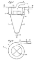
- the cyclone comprises: an inlet spiral with an acceleration nozzle; a cylindrical separation body; a cone for receiving the liquid-wet particle mixture; and a central chimney for the outlet of the gaseous fluid; said central chimney of the cyclone can be provided with an anti-rotation means.
- the installation 1, preferably mobile, for pumping a liquid or gaseous fluid, such as in particular air, charged with solid particles, or possibly liquids such as spray, comprises at least one reservoir 2 for collecting the liquid fraction and / or the heaviest solid particles dispersed in the gaseous fluid, the reservoir 2 comprising at least one fluid inlet 3 and being connected to one end of at least one pipe 4, the other end of which is connected to means 5 for evacuating the tank 2; the end of the pipe 4 connected to the tank 2 can be provided with a filling stop device (float).
- float filling stop device
- Such a pumping installation can be mounted on a vehicle (not shown), in particular a truck trailer, and is thus easily movable from one work site to another.
- a liquid ring pump As means 5 for creating the vacuum in the tank 2, one can use, for example, a liquid ring pump, or a vane pump.
- the pumping installation 1 is particularly remarkable in that it comprises a device 6 for trapping the lightest particles entrained by the flow of gaseous fluid in the pipe 4, said device 6 being connected to the pipe 4 between the tank 2 and the means 5 for creating a vacuum, and extracting the light particles from the pipe 4.
- the device 6 for trapping light particles comprises at least one means forming a cyclone 7 and, as illustrated, means 8 for wetting the lighter solid particles, for example by injecting water into the flow of gaseous fluid, provided upstream of cyclone 7.
- the device 6 for trapping the particles comprises a tank 9, connected to the outlet of the cyclone 7 by an evacuation pipe 10, the tank 9 collecting the liquid mixture (in particular water) - particles, mixture which forms a mud which will settle at the bottom of the tank.
- the liquid mixture in particular water
- the means 8 for wetting the particles comprise at least one pump 11 connected, downstream, by a pipe 12 to the pipe 4, connecting the main tank 2 and the pump 5, in the vicinity of the inlet of the cyclone 7 and, upstream , preferably to the tank 9 previously partially filled with wetting liquid, in particular water, and this by means of a pipe 13.
- the pipes 12 and 13 are provided with valves 14 and 15, respectively.
- the pump 11 can be connected, on the one hand upstream, to the bottom of the tank 9 by a pipe 16 and, on the other hand, downstream, to the collection tank 2 by a pipe 17; the lines 16 and 17 being provided with valves 18 and 19, respectively.
- the cyclone 7, used in the installation of the invention comprises an inlet spiral 21 with acceleration nozzle 22; a cylindrical separation body 23; a cone 24 for receiving the liquid-wet particles mixture and a central chimney 25 for the outlet of the gaseous fluid; the central chimney 25 of the cyclone being provided with an anti-rotation cross 26.
- the pumping installation according to the invention operates in the following manner.
- the pump 5 creates a vacuum in the tank 2.
- the pressure difference between the inside and the outside of the tank causes the transfer of the fluid from the outside to the inside of the tank at very high speed.
- the vacuum is maintained at the pressure near the saturation vapor pressure of the liquid, at a given temperature. If the liquid is transported in emulsion with air, it is necessary to separate the air from the liquid; this is essentially done in the tank. To obtain this separation, or plays, at the same time, on the difference in density of the air and of the pumped liquid, the speed of entry into the tank, and the speed of return of the air at the exit of the tank.
- the filling takes place in the vicinity of the rear bottom of the tank, and the fluid inlet pipe 3 extends, inside the tank 2, towards the front of the latter and upwards; the air is pumped upstream of this pipe 3.
- the speed of penetration into the tank is such that all the dense particles are thrown forward and trapped in the tank, while the return passage of the air takes place through a very large section, and therefore at low speed; this low speed preventing the suspension of dense particles.
- the maximum filling of the tank is calculated as a function of the free space necessary for the return of air at low speed, that is to say approximately ten times the cross section of the filling pipe.
- An automatic level (not shown) can be provided, which, depending on the maximum level chosen, will stop the installation; a switching system allowing to play on the maximum level in the tank.
- the device 6 To trap these particles and extract them from the flow of gaseous fluid circulating in the pipe 4, the device 6 according to the invention is used, comprising, in particular, the cyclone 7 and the means 8 for wetting the light particles which makes it possible to weigh down those here, so as to facilitate their extraction from the flow of gaseous fluid by the cyclone.
- the tank 9 is filled with water to a given volume, the free volume corresponding to the storage volume of the sludge formed by the mixture of light solid particles-water.
- the pump 11 sucks the water in the tank 9, about halfway up, and delivers it into the pipe 12 at the inlet of the cyclone 7.
- the inlet of the cyclone 7 comprises an acceleration nozzle 22 so as to, d on the one hand, create an intimate air-water-dust mixture due to the atomization of the water obtained by the high speed of the air in cyclone 7, and, on the other hand, create in the cyclone a maximum rate of turn to obtain air-water centrifugation.
- the discharge pipe 10 of the cyclone 7 can be connected to the dome of the tank, or, as in the embodiment shown, the discharge can be provided so as to immerse in the volume of water, a pipe 20 d pressure balancing then being necessary between the surface of the water body and the interior of the cyclone.
- the pump 11 can be connected, both to the bottom of the tank 9 and to the main tank 2 so as to allow the transfer of the sludge from the tank 9 to the collection tank 2.
- An automatic cleaning device can optionally be implemented. This device will be operational during the entire operating time.
- the cyclone makes it possible to capture the spray, these being transferred to the collection tank once the maximum tolerable level reached in the auxiliary tank 9.
- the vacuum pump does not more risk of entraining other fluids than gaseous fluids towards the vacuum pump.
Priority Applications (4)
| Application Number | Priority Date | Filing Date | Title |
|---|---|---|---|
| FR858515108A FR2591675B1 (fr) | 1985-10-11 | 1985-10-11 | Installation de pompage d'un fluide charge de particules, et vehicule equipe de ladite installation |
| AT87400643T ATE68717T1 (de) | 1987-03-23 | 1987-03-23 | Einrichtung zum absaugen eines partikelbeladenen fluids und ein mit dieser einrichtung ausgeruestetes fahrzeug. |
| DE8787400643T DE3774118D1 (de) | 1987-03-23 | 1987-03-23 | Einrichtung zum absaugen eines partikelbeladenen fluids und ein mit dieser einrichtung ausgeruestetes fahrzeug. |
| EP87400643A EP0283625B1 (de) | 1987-03-23 | 1987-03-23 | Einrichtung zum Absaugen eines partikelbeladenen Fluids und ein mit dieser Einrichtung ausgerüstetes Fahrzeug |
Applications Claiming Priority (1)
| Application Number | Priority Date | Filing Date | Title |
|---|---|---|---|
| EP87400643A EP0283625B1 (de) | 1987-03-23 | 1987-03-23 | Einrichtung zum Absaugen eines partikelbeladenen Fluids und ein mit dieser Einrichtung ausgerüstetes Fahrzeug |
Publications (2)
| Publication Number | Publication Date |
|---|---|
| EP0283625A1 true EP0283625A1 (de) | 1988-09-28 |
| EP0283625B1 EP0283625B1 (de) | 1991-10-23 |
Family
ID=8198194
Family Applications (1)
| Application Number | Title | Priority Date | Filing Date |
|---|---|---|---|
| EP87400643A Expired - Lifetime EP0283625B1 (de) | 1985-10-11 | 1987-03-23 | Einrichtung zum Absaugen eines partikelbeladenen Fluids und ein mit dieser Einrichtung ausgerüstetes Fahrzeug |
Country Status (4)
| Country | Link |
|---|---|
| EP (1) | EP0283625B1 (de) |
| AT (1) | ATE68717T1 (de) |
| DE (1) | DE3774118D1 (de) |
| FR (1) | FR2591675B1 (de) |
Cited By (1)
| Publication number | Priority date | Publication date | Assignee | Title |
|---|---|---|---|---|
| WO2015022458A1 (fr) * | 2013-08-14 | 2015-02-19 | Ortec Expansion | Procédé et unité de pompage de produits inflammables susceptibles de former une atmosphere explosive |
Families Citing this family (2)
| Publication number | Priority date | Publication date | Assignee | Title |
|---|---|---|---|---|
| FR2673861B1 (fr) * | 1991-03-11 | 1995-03-03 | Gb 2000 International | Installation de nettoyage par aspiration centralisee. |
| US11794138B2 (en) * | 2020-10-19 | 2023-10-24 | Sierra Space Corporation | Microgravity system phase separator |
Citations (5)
| Publication number | Priority date | Publication date | Assignee | Title |
|---|---|---|---|---|
| US1544981A (en) * | 1924-09-30 | 1925-07-07 | Hasse Frank Clarence | Dust and dirt collector |
| DE2256678A1 (de) * | 1972-11-18 | 1974-05-22 | Koerting Ag | Fliehkraftabscheider |
| US4065527A (en) * | 1976-02-19 | 1977-12-27 | Graber David A | Method and apparatus for interaction of gas and liquid |
| US4218226A (en) * | 1978-07-25 | 1980-08-19 | Link Built Products of Ocala, Inc. | Vacuum apparatus |
| DE3224270A1 (de) * | 1981-06-29 | 1983-01-13 | Hamworthy Engineering Ltd., Poole, Dorset | Vorrichtung zur reinigung von gasen |
-
1985
- 1985-10-11 FR FR858515108A patent/FR2591675B1/fr not_active Expired - Lifetime
-
1987
- 1987-03-23 DE DE8787400643T patent/DE3774118D1/de not_active Expired - Lifetime
- 1987-03-23 EP EP87400643A patent/EP0283625B1/de not_active Expired - Lifetime
- 1987-03-23 AT AT87400643T patent/ATE68717T1/de not_active IP Right Cessation
Patent Citations (5)
| Publication number | Priority date | Publication date | Assignee | Title |
|---|---|---|---|---|
| US1544981A (en) * | 1924-09-30 | 1925-07-07 | Hasse Frank Clarence | Dust and dirt collector |
| DE2256678A1 (de) * | 1972-11-18 | 1974-05-22 | Koerting Ag | Fliehkraftabscheider |
| US4065527A (en) * | 1976-02-19 | 1977-12-27 | Graber David A | Method and apparatus for interaction of gas and liquid |
| US4218226A (en) * | 1978-07-25 | 1980-08-19 | Link Built Products of Ocala, Inc. | Vacuum apparatus |
| DE3224270A1 (de) * | 1981-06-29 | 1983-01-13 | Hamworthy Engineering Ltd., Poole, Dorset | Vorrichtung zur reinigung von gasen |
Cited By (2)
| Publication number | Priority date | Publication date | Assignee | Title |
|---|---|---|---|---|
| WO2015022458A1 (fr) * | 2013-08-14 | 2015-02-19 | Ortec Expansion | Procédé et unité de pompage de produits inflammables susceptibles de former une atmosphere explosive |
| FR3009742A1 (fr) * | 2013-08-14 | 2015-02-20 | Ortec Expansion | Procede et unite de pompage de produits inflammables susceptibles de former une atmosphere explosive |
Also Published As
| Publication number | Publication date |
|---|---|
| FR2591675A1 (fr) | 1987-06-19 |
| DE3774118D1 (de) | 1991-11-28 |
| FR2591675B1 (fr) | 1992-05-22 |
| ATE68717T1 (de) | 1991-11-15 |
| EP0283625B1 (de) | 1991-10-23 |
Similar Documents
| Publication | Publication Date | Title |
|---|---|---|
| FR2578170A1 (fr) | Separateur pour separer un gaz d'un liquide. | |
| FR2499122A1 (fr) | Dispositif de dragage | |
| FR2752416A1 (fr) | Dispositif et procede de recuperation de vapeurs d'essence faisant appel a une detection d'oxygene | |
| WO2007141448A1 (fr) | Dispositif mélangeur gaz-liquide | |
| FR2480402A1 (fr) | Perfectionnements apportes aux appareils de dissipation de pression d'un fluide | |
| EP0283625B1 (de) | Einrichtung zum Absaugen eines partikelbeladenen Fluids und ein mit dieser Einrichtung ausgerüstetes Fahrzeug | |
| FR2604639A1 (fr) | Degazeur pour la separation de gaz ou de vapeurs, hors de courants liquide/gaz ou liquides/vapeurs dans des canalisations | |
| FR2864169A1 (fr) | Filtre a carburant a evacuation d'eau facilitee | |
| FR2726203A1 (fr) | Separateur a flottation centripete, notamment pour le traitement d'effluents aqueux charges | |
| EP0469977A1 (de) | Unterdrucksanitäranlage, versehen mit einem Gas enthaltenden Flüssigkeitsreiniger | |
| CA2304402C (fr) | Installation de distribution d'hydrocarbures liquides equipee d'un moyen de recuperation des vapeurs | |
| EP0296917B1 (de) | Vorrichtung zur kontinuierlichen Zirkulation einer Flüssigkeit zur Probenahme oder Kontrolle dieser Flüssigkeit | |
| FR2790255A1 (fr) | Systeme et procede de detection, par un detecteur de densite, de la recuperation de vapeur recuperee a bord de vehicules | |
| FR2829703A1 (fr) | Dispositif de separation de l'eau contenue dans du gazole destine a alimenter un moteur diesel | |
| FR2818203A1 (fr) | Systeme de mise a l'air et/ou de compensation de pression pour un recipient a carburant | |
| EP4006340A1 (de) | Vorrichtung und verfahren zum pumpen von produkten mit geringer verdampfung unter vakuum | |
| FR2809179A1 (fr) | Dispositif d'amorcage automatique de cannes de prelevement de fluides | |
| FR3109894A1 (fr) | Dispositif de collecte de particules et véhicule équipé d’un tel dispositif | |
| FR2474328A1 (fr) | Dispositif de separation de produits liquides non miscibles de densite differente | |
| EP1500419B1 (de) | Automatische Verschlussanordnung für Abscheider für leichte Flüssigkeiten wie Kohlenwasserstoffe | |
| WO2003006296A1 (fr) | Circuit hydraulique de freinage avec moyens de filtration. | |
| EP0648523B1 (de) | Vorrichtung und Verfahren zum Entgasen eines Hydraulikkreislaufs | |
| FR2711072A1 (fr) | Séparateur-décanteur vertical à cellule lambellaire nettoyable destiné au traitement des eaux. | |
| EP0344063A1 (de) | Entgasungsvorrichtung des Brennstoffzufuhrs einer Brennkraftmaschine | |
| FR3134523A1 (fr) | Dispositif de captation de particules liquides dans un flux gazeux |
Legal Events
| Date | Code | Title | Description |
|---|---|---|---|
| PUAI | Public reference made under article 153(3) epc to a published international application that has entered the european phase |
Free format text: ORIGINAL CODE: 0009012 |
|
| AK | Designated contracting states |
Kind code of ref document: A1 Designated state(s): AT BE CH DE ES GB GR IT LI LU NL SE |
|
| 17P | Request for examination filed |
Effective date: 19881024 |
|
| 17Q | First examination report despatched |
Effective date: 19900612 |
|
| GRAA | (expected) grant |
Free format text: ORIGINAL CODE: 0009210 |
|
| AK | Designated contracting states |
Kind code of ref document: B1 Designated state(s): AT BE CH DE ES GB GR IT LI LU NL SE |
|
| PG25 | Lapsed in a contracting state [announced via postgrant information from national office to epo] |
Ref country code: SE Effective date: 19911023 Ref country code: NL Effective date: 19911023 Ref country code: GR Free format text: LAPSE BECAUSE OF FAILURE TO SUBMIT A TRANSLATION OF THE DESCRIPTION OR TO PAY THE FEE WITHIN THE PRESCRIBED TIME-LIMIT Effective date: 19911023 Ref country code: AT Effective date: 19911023 |
|
| REF | Corresponds to: |
Ref document number: 68717 Country of ref document: AT Date of ref document: 19911115 Kind code of ref document: T |
|
| REF | Corresponds to: |
Ref document number: 3774118 Country of ref document: DE Date of ref document: 19911128 |
|
| GBT | Gb: translation of ep patent filed (gb section 77(6)(a)/1977) | ||
| ITF | It: translation for a ep patent filed |
Owner name: MODIANO & ASSOCIATI S.R.L. |
|
| PG25 | Lapsed in a contracting state [announced via postgrant information from national office to epo] |
Ref country code: ES Free format text: LAPSE BECAUSE OF FAILURE TO SUBMIT A TRANSLATION OF THE DESCRIPTION OR TO PAY THE FEE WITHIN THE PRESCRIBED TIME-LIMIT Effective date: 19920203 |
|
| NLV1 | Nl: lapsed or annulled due to failure to fulfill the requirements of art. 29p and 29m of the patents act | ||
| PG25 | Lapsed in a contracting state [announced via postgrant information from national office to epo] |
Ref country code: LU Free format text: LAPSE BECAUSE OF NON-PAYMENT OF DUE FEES Effective date: 19920331 Ref country code: LI Effective date: 19920331 Ref country code: CH Effective date: 19920331 Ref country code: BE Effective date: 19920331 |
|
| PLBE | No opposition filed within time limit |
Free format text: ORIGINAL CODE: 0009261 |
|
| STAA | Information on the status of an ep patent application or granted ep patent |
Free format text: STATUS: NO OPPOSITION FILED WITHIN TIME LIMIT |
|
| BERE | Be: lapsed |
Owner name: ETS. RIVARD S.A. Effective date: 19920331 |
|
| 26N | No opposition filed | ||
| REG | Reference to a national code |
Ref country code: CH Ref legal event code: PL |
|
| PGFP | Annual fee paid to national office [announced via postgrant information from national office to epo] |
Ref country code: GB Payment date: 19950314 Year of fee payment: 9 |
|
| PGFP | Annual fee paid to national office [announced via postgrant information from national office to epo] |
Ref country code: DE Payment date: 19950410 Year of fee payment: 9 |
|
| PG25 | Lapsed in a contracting state [announced via postgrant information from national office to epo] |
Ref country code: GB Effective date: 19960323 |
|
| GBPC | Gb: european patent ceased through non-payment of renewal fee |
Effective date: 19960323 |
|
| PG25 | Lapsed in a contracting state [announced via postgrant information from national office to epo] |
Ref country code: DE Effective date: 19961203 |
|
| PG25 | Lapsed in a contracting state [announced via postgrant information from national office to epo] |
Ref country code: IT Free format text: LAPSE BECAUSE OF NON-PAYMENT OF DUE FEES;WARNING: LAPSES OF ITALIAN PATENTS WITH EFFECTIVE DATE BEFORE 2007 MAY HAVE OCCURRED AT ANY TIME BEFORE 2007. THE CORRECT EFFECTIVE DATE MAY BE DIFFERENT FROM THE ONE RECORDED. Effective date: 20050323 |