EP0282772A2 - Betriebsverfahren für eine Klimaanlage - Google Patents
Betriebsverfahren für eine Klimaanlage Download PDFInfo
- Publication number
- EP0282772A2 EP0282772A2 EP88102637A EP88102637A EP0282772A2 EP 0282772 A2 EP0282772 A2 EP 0282772A2 EP 88102637 A EP88102637 A EP 88102637A EP 88102637 A EP88102637 A EP 88102637A EP 0282772 A2 EP0282772 A2 EP 0282772A2
- Authority
- EP
- European Patent Office
- Prior art keywords
- compressor
- indoor
- air conditioning
- indoor heat
- expansion valves
- Prior art date
- Legal status (The legal status is an assumption and is not a legal conclusion. Google has not performed a legal analysis and makes no representation as to the accuracy of the status listed.)
- Granted
Links
- 238000004378 air conditioning Methods 0.000 title claims abstract description 23
- 238000011017 operating method Methods 0.000 title 1
- 239000003507 refrigerant Substances 0.000 claims abstract description 60
- 239000007788 liquid Substances 0.000 claims abstract description 14
- 238000005057 refrigeration Methods 0.000 claims abstract description 14
- 238000000034 method Methods 0.000 claims description 9
- 238000001816 cooling Methods 0.000 description 8
- 238000010438 heat treatment Methods 0.000 description 4
- 230000001681 protective effect Effects 0.000 description 3
- 230000003247 decreasing effect Effects 0.000 description 2
- 230000002441 reversible effect Effects 0.000 description 2
- 230000001143 conditioned effect Effects 0.000 description 1
- 238000007796 conventional method Methods 0.000 description 1
- 238000010586 diagram Methods 0.000 description 1
- 230000004069 differentiation Effects 0.000 description 1
- 230000010354 integration Effects 0.000 description 1
- 238000000926 separation method Methods 0.000 description 1
- 230000002123 temporal effect Effects 0.000 description 1
- 238000010257 thawing Methods 0.000 description 1
Images


Classifications
-
- F—MECHANICAL ENGINEERING; LIGHTING; HEATING; WEAPONS; BLASTING
- F25—REFRIGERATION OR COOLING; COMBINED HEATING AND REFRIGERATION SYSTEMS; HEAT PUMP SYSTEMS; MANUFACTURE OR STORAGE OF ICE; LIQUEFACTION SOLIDIFICATION OF GASES
- F25B—REFRIGERATION MACHINES, PLANTS OR SYSTEMS; COMBINED HEATING AND REFRIGERATION SYSTEMS; HEAT PUMP SYSTEMS
- F25B5/00—Compression machines, plants or systems, with several evaporator circuits, e.g. for varying refrigerating capacity
-
- F—MECHANICAL ENGINEERING; LIGHTING; HEATING; WEAPONS; BLASTING
- F25—REFRIGERATION OR COOLING; COMBINED HEATING AND REFRIGERATION SYSTEMS; HEAT PUMP SYSTEMS; MANUFACTURE OR STORAGE OF ICE; LIQUEFACTION SOLIDIFICATION OF GASES
- F25B—REFRIGERATION MACHINES, PLANTS OR SYSTEMS; COMBINED HEATING AND REFRIGERATION SYSTEMS; HEAT PUMP SYSTEMS
- F25B41/00—Fluid-circulation arrangements
- F25B41/30—Expansion means; Dispositions thereof
- F25B41/31—Expansion valves
- F25B41/34—Expansion valves with the valve member being actuated by electric means, e.g. by piezoelectric actuators
-
- F—MECHANICAL ENGINEERING; LIGHTING; HEATING; WEAPONS; BLASTING
- F25—REFRIGERATION OR COOLING; COMBINED HEATING AND REFRIGERATION SYSTEMS; HEAT PUMP SYSTEMS; MANUFACTURE OR STORAGE OF ICE; LIQUEFACTION SOLIDIFICATION OF GASES
- F25B—REFRIGERATION MACHINES, PLANTS OR SYSTEMS; COMBINED HEATING AND REFRIGERATION SYSTEMS; HEAT PUMP SYSTEMS
- F25B49/00—Arrangement or mounting of control or safety devices
- F25B49/02—Arrangement or mounting of control or safety devices for compression type machines, plants or systems
-
- F—MECHANICAL ENGINEERING; LIGHTING; HEATING; WEAPONS; BLASTING
- F25—REFRIGERATION OR COOLING; COMBINED HEATING AND REFRIGERATION SYSTEMS; HEAT PUMP SYSTEMS; MANUFACTURE OR STORAGE OF ICE; LIQUEFACTION SOLIDIFICATION OF GASES
- F25B—REFRIGERATION MACHINES, PLANTS OR SYSTEMS; COMBINED HEATING AND REFRIGERATION SYSTEMS; HEAT PUMP SYSTEMS
- F25B13/00—Compression machines, plants or systems, with reversible cycle
-
- F—MECHANICAL ENGINEERING; LIGHTING; HEATING; WEAPONS; BLASTING
- F25—REFRIGERATION OR COOLING; COMBINED HEATING AND REFRIGERATION SYSTEMS; HEAT PUMP SYSTEMS; MANUFACTURE OR STORAGE OF ICE; LIQUEFACTION SOLIDIFICATION OF GASES
- F25B—REFRIGERATION MACHINES, PLANTS OR SYSTEMS; COMBINED HEATING AND REFRIGERATION SYSTEMS; HEAT PUMP SYSTEMS
- F25B2313/00—Compression machines, plants or systems with reversible cycle not otherwise provided for
- F25B2313/023—Compression machines, plants or systems with reversible cycle not otherwise provided for using multiple indoor units
- F25B2313/0233—Compression machines, plants or systems with reversible cycle not otherwise provided for using multiple indoor units in parallel arrangements
-
- F—MECHANICAL ENGINEERING; LIGHTING; HEATING; WEAPONS; BLASTING
- F25—REFRIGERATION OR COOLING; COMBINED HEATING AND REFRIGERATION SYSTEMS; HEAT PUMP SYSTEMS; MANUFACTURE OR STORAGE OF ICE; LIQUEFACTION SOLIDIFICATION OF GASES
- F25B—REFRIGERATION MACHINES, PLANTS OR SYSTEMS; COMBINED HEATING AND REFRIGERATION SYSTEMS; HEAT PUMP SYSTEMS
- F25B2600/00—Control issues
- F25B2600/02—Compressor control
- F25B2600/021—Inverters therefor
-
- F—MECHANICAL ENGINEERING; LIGHTING; HEATING; WEAPONS; BLASTING
- F25—REFRIGERATION OR COOLING; COMBINED HEATING AND REFRIGERATION SYSTEMS; HEAT PUMP SYSTEMS; MANUFACTURE OR STORAGE OF ICE; LIQUEFACTION SOLIDIFICATION OF GASES
- F25B—REFRIGERATION MACHINES, PLANTS OR SYSTEMS; COMBINED HEATING AND REFRIGERATION SYSTEMS; HEAT PUMP SYSTEMS
- F25B2600/00—Control issues
- F25B2600/25—Control of valves
- F25B2600/2513—Expansion valves
-
- Y—GENERAL TAGGING OF NEW TECHNOLOGICAL DEVELOPMENTS; GENERAL TAGGING OF CROSS-SECTIONAL TECHNOLOGIES SPANNING OVER SEVERAL SECTIONS OF THE IPC; TECHNICAL SUBJECTS COVERED BY FORMER USPC CROSS-REFERENCE ART COLLECTIONS [XRACs] AND DIGESTS
- Y02—TECHNOLOGIES OR APPLICATIONS FOR MITIGATION OR ADAPTATION AGAINST CLIMATE CHANGE
- Y02B—CLIMATE CHANGE MITIGATION TECHNOLOGIES RELATED TO BUILDINGS, e.g. HOUSING, HOUSE APPLIANCES OR RELATED END-USER APPLICATIONS
- Y02B30/00—Energy efficient heating, ventilation or air conditioning [HVAC]
- Y02B30/70—Efficient control or regulation technologies, e.g. for control of refrigerant flow, motor or heating
Definitions
- the present invention relates to an air conditioning system comprising a heat pump type refrigeration cycle in which a plurality of indoor units are connected to an outdoor unit, and a refrigerant flow is controlled by electric expansion valves under PID control.
- the present invention also relates to an operation method for the above-mentioned air conditioning system.
- an opening degree of an electric expansion valve is set to a particular initial level at a start of the respective operational conditions such as cooling, heating and defrosting modes, in response thereto.
- the operational condition changes have not been taken into consideration, such as change in capacity of the compressor and in the number of the operating indoor units during the operation of the system. Accordingly, in case of the air conditioning system in which the compressor is controlled in the capacity thereof by an inverter or in which a plurality of outdoor units are connected to an indoor unit, it is impossible to make the refrigerant conditions steady within a short period of time, which are disturbed due to the change of the operational conditions of the system.
- an object of the present invention is to provide an air conditioning system which can make the operational conditions of the refrigerant within a short period of time even if the operational conditions of the system are changed.
- an air conditioning system including a sensor means for detecting an indoor temperature and a temperature of gaseous refrigerant, a terminal board for changing set-up indoor temperature, a primary controller for controlling an input frequency of the compressor and the number of the operating indoor units, and a means for receiving signals from the primary controller and the sensor means and outputting a command representing an opening degree corresponding to the operational conditions of the system, on the basis of such received signals, to the expansion valve, whereby the expansion valve is set, when the operational conditions of the system are changed, in the opening degree thereof to the desired level which correspond to such changed operational conditions.
- a refrigeration cycle of an air conditioning system comprises a single outdoor unit A and three indoor units B, C and D connected to the outdoor unit A.
- the indoor unit A includes a compressor 1, a four-way valve 2, an accumulator 3, an outdoor heat exchanger 4 and a receiver 5.
- the indoor units B, C and D comprise indoor heat exchangers 8b, 8c and 8d, respectively.
- Electric reversible expansion valves 9b, 9c and 9d are disposed in the respective liquid side branched pipes 10b, 10c and 10d through which the low temperature and low pressure liquid refrigerant flows during the cooling mode.
- solenoid valves 11b, 11c and 11d are disposed in the respective gas side branched pipes 12b, 12c and 13d through which the low temperature and low pressure gaseous refrigerant flows during the cooling operation.
- the receiver 5 is disposed in a liquid side primary pipe 6 through which the liquid refrigerant flows during the cooling mode.
- a gas side primary pipe 7 through which the low temperature and low pressure gaseous refrigerant flows during the cooling operation is connected to the four-way valve 2.
- a control system which includes a primary controller 13 for controlling operational conditions such as frequency of the compressor or the like, a terminal board 14 for delivering set-up values of a room temperature into the primary controller 13, a sensor means 15 for detecting the room temperature, the gaseous refrigerant temperature and the like, and an expansion valve opening degree outputting means 16 for calculating and outputting a suitable opening degree of the expansion valve is accordance with the operational condition.
- a primary controller 13 for controlling operational conditions such as frequency of the compressor or the like
- a terminal board 14 for delivering set-up values of a room temperature into the primary controller 13
- a sensor means 15 for detecting the room temperature, the gaseous refrigerant temperature and the like
- an expansion valve opening degree outputting means 16 for calculating and outputting a suitable opening degree of the expansion valve is accordance with the operational condition.
- Fig. 2 shows the compressor input frequency change 17, the expansion valve opening degree change 18 and the change 19 of the temperature (pressure) of the gaseous refrigerant discharged from the compressor, respectively during a control operation of the electric expansion valves in accordance with a conventional PID (proportion, integration and differentiation) control.
- the reference characters 17a, 18a and 19a denote the respective changes when the compressor input frequency is increased and the reference characters 17b, 18b and 19b denote the respective changes when the compressor input frequency is decreased.
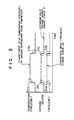
- FIG. 3 shows the compressor input frequency change 20, the expansion valve opening degree change 21 and the change 22 of the temperature (pressure) of the gaseous refrigerant discharged from the compressor, respectively during a control operation of the electric expansion valves in accordance with the present invention in addition to the conventional PID control.
- the reference characters 20a, 21a and 22a in Fig. 3 denote the respective changes when the compressor input frequency is increased and the reference characters 20b, 21b and 22b denote the respective changes when the compressor input frequency is decreased.
- Fig. 4 shows a flow chart of such control.
- the four-way valve 2 is switched over in a position as shown in Fig. 1.
- the high temperature and high pressure gaseous refrigerant compressed in the compressor 1 is pumped out to the outdoor heat exchanger 4 in which the gaseous refrigerant is heat-exchanged with and cooled by air forcedly blown by a blower so as to become the high pressure liquid refrigerant.
- a part of the liquid refrigerant is stored in the receiver 5 but almost thereof is allowed to flow through the liquid side primary pipe 6 into the liquid side branched pipes 10b to 10d.
- the liquid refrigerant is reduced in the pressure thereof and expanded in the electric expansion valves 9b, 9c and 9d so as to become the low temperature and low pressure gaseous refrigerant.
- gaseous refrigerant is introduced into the respective indoor heat exchangers 8b, 8c and 8d in the indoor units B, C and D.
- an interior air in the room forcedly blown by a blower is heat-exchanged with the gaseous refrigerant and cooled to air condition the room.
- the low pressure refrigerant gas which has been heat-exchanged with the interior air flows through the gas side branched pipes 12b, 12c and 12d in the outlet side of the indoor heat exchangers 8b, 8c and 8d.
- the low pressure refrigerant flows through the respective solenoid valves 11b, 11c and 11d and thereafter flows through the gas side primary pipe 7 into the accumulator 3 via the four-way valve 2.
- gas/liquid separation is effected so that the gaseous refrigerant is solely introduced into the compressor 1 to complete the refrigeration cycle.
- the compressor 1 is frequency controlled in the input frequency thereof by means of an inverter in the primary controller 13 in accordance with the set-up room temperature and the room temperature detected by the sensor 15, so that the capacity of the compressor 1 is controlled.
- the respective electric expansion valves 9b, 9c and 9d is operated under the PID control in accordance with the indoor heat exchanger temperature and the set-up room temperature, the room temperature and the degree of superheat of the refrigerant, and the ability of the indoor unit.
- the four-way valve 2 is so switched over that the high temperature and high pressure gaseous refrigerant is allowed to flow through the solenoid valves 11b, 11c and 11d into the indoor heat exchangers 8b, 8c and 8d. Therefore, interior air is heated and heating operation is performed.
- the refrigerant flows to form a refrigeration cycle reverse to the above-mentioned cycle in the cooling operation.
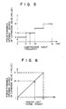
- the primary controller 13 receives data representing such changes and frequency-controls the compressor in the input frequency thereof in accordance with the operational conditions, in compliance with the control flow shown in Fig. 4. Further, the opening degrees of the expansion valves 9b, 9c and 9d is promptly controlled by the expansion valve opening degree outputting means 16 so as to satisfy the predetermined relationship between the input frequency and the opening degree of the expansion valve shown in Fig. 5.
- the discrete opening degrees of the expansion valve between d and e is so determined that the refrigerant conditions are stabilized in response to a compressor input frequency between a lower limit a and an upper limit b .
- the pattern of such relationship between the compressor input frequency and the opening degree of the expansion valve is stored in the expansion valve opening degree outputting means 16. If it is decided by the primary controller 13 that the compressor input frequency is changed, for example, to a frequency C, the means 16 calculates or selects the opening degree f on the basis of the numerically expressed above-mentioned relationship (Fig. 5) stored in the mans 16.
- the means 16 outputs the value f for a predetermined period of time into the respective expansion valves associated with the indoor units which have been subjected to the PID control.
- the expansion valve opening degree is set at a constant value f in a frequency zone between C1 and C2. A plurality of such zones are provided between the frequency a and b .
- the opening degree of the expansion valve is changed to the set-up value which is predetermined on the basis of the relationship between the horse power of the operating indoor unit and the opening degree (pulse) of the expansion valve as shown in Fig. 6.
- the opening degrees of the expansion valve between j and k is so determined that the refrigerant conditions are stabilized in response to the horse power of the operating indoor unit between a lower limit g and an upper limit h .
- the pattern of such relationship between the horse power of the operating indoor unit and the opening degree of the expansion valve associated therewith is stored in 16.
- the means 16 receives the informations from the primary controller 13 and calculates or selects the opening degree m on the basis of the numerically expressed above-mentioned relationship (Fig. 6) stored in the means 16.
- the means 16 outputs the value m for a predetermined period of time into the respective expansion valves associated with the indoor units which have been subjected to the PID control or into the expansion valve associated with the inoperating indoor unit to be started. Thereafter, such expansion valve are subjected to the PID control again, so that it is possible to stabilize the refrigerant condition within a short period of time.
- the opening degree of the electric expansion valve is controlled solely by the PID control so as to stabilize the temperature of the refrigerant from the compressor even if the conditions of the refrigerant is fluctuated as described above.
- the PID control it is impossible to well follow the large fluctuation of the refrigerant conditions, e.g. change of the capacity of the compressor, as shown in Fig. 2.
- the opening degree of the expansion valve is changed slowly or moderately to response such change of the input frequency, as designated by the curve 18 in Fig. 2, resulting in a temporal excessive increase of the temperature of the refrigerant from the compressor as designated by 19a.
- the predetermined opening degrees of the expansion valve which correspond to the compressor input frequency are calculated in advance, which can able to stabilize the refrigerant conditions after the load thereof is changed, and when the input frequency is changed, the PID control is interrupted and the opening degree of the expansion valve is set to the predetermined degree which correspond to the changed input frequency. Therefore, it can be possible to stabilize the refrigerant conditions within a short period of time. After the refrigerant conditions become steady, the PID control is applied again. Accordingly, in case that the increase of the compressor input frequency is occurred as designated by 20a in Fig.
- the opening degree of the expansion valve is set to the steady opening degree without any time lag as designated by 21a, whereby the temperature of the gaseous refrigerant from the compressor becomes steady state within a short period of time as designated by 21a, which temperature represents the refrigerant condition. This phenomenon may occur on the decrease of the input frequency as designated by 20b, 21b and 22b.
- the temperature of the gaseous refrigerant from the compressor is employed as a parameter representative of the refrigerant condition.
- the present invention is not limited to this, any other parameter, e.g. the pressure of the gaseous refrigerant from the compressor may be employed.
- the primary controller controls the compressor input frequency on the basis of the change of the set-up room temperature and the room temperature, and sets and controls the indoor units selected by the user.
- the PID control is interrupted and then the expansion valve opening degree outputting means outputs a command, in accordance with the operation conditions thereof, to the expansion valve to change the opening degree thereof into the set opening degree predetermined in accordance with the operation conditions, by which set opening degree the refrigeration cycle of the heat pump type is stabilized. Accordingly, it becomes possible to minimize the delay of time between the time when the operation condition changes and when the refrigerant condition becomes steady state. Accordingly it can be possible to prevent the compressor protective means to operate due to the excessive increase of the temperature of the gaseous refrigerant from the compressor.
- the present invention provides a operation method for an air conditioning system, in which, on the basis of the signal representing the air conditioning load or the signal representing the change of the number of the operating indoor units, the compressor input frequency and the degree of the expansion valve are simultaneously so controlled that the temperature (pressure) of the gaseous refrigerant from the compressor can be smoothly changed.
- the present invention also provide a control method for an air conditioning system, in which, on the basis of either the signal representing the air conditioning load or the signal representing the change of the number of the operating indoor units, the compressor input frequency and the degree of the expansion valve are simultaneously controlled.
Applications Claiming Priority (2)
| Application Number | Priority Date | Filing Date | Title |
|---|---|---|---|
| JP62063853A JP2735188B2 (ja) | 1987-03-20 | 1987-03-20 | 空気調和装置 |
| JP63853/87 | 1987-03-20 |
Publications (3)
| Publication Number | Publication Date |
|---|---|
| EP0282772A2 true EP0282772A2 (de) | 1988-09-21 |
| EP0282772A3 EP0282772A3 (en) | 1989-10-04 |
| EP0282772B1 EP0282772B1 (de) | 1992-05-13 |
Family
ID=13241307
Family Applications (1)
| Application Number | Title | Priority Date | Filing Date |
|---|---|---|---|
| EP88102637A Expired - Lifetime EP0282772B1 (de) | 1987-03-20 | 1988-02-23 | Betriebsverfahren für eine Klimaanlage |
Country Status (4)
| Country | Link |
|---|---|
| EP (1) | EP0282772B1 (de) |
| JP (1) | JP2735188B2 (de) |
| KR (1) | KR930012233B1 (de) |
| DE (1) | DE3870942D1 (de) |
Cited By (8)
| Publication number | Priority date | Publication date | Assignee | Title |
|---|---|---|---|---|
| US5131237A (en) * | 1990-04-04 | 1992-07-21 | Danfoss A/S | Control arrangement for a refrigeration apparatus |
| EP0604356A1 (de) * | 1992-12-24 | 1994-06-29 | Carrier Corporation | Regelung eines Expansionsventils |
| WO1996027108A1 (en) * | 1995-02-28 | 1996-09-06 | American Standard Inc. | Feed forward control of expansion valve |
| EP1355207A1 (de) * | 2002-04-16 | 2003-10-22 | Otto Egelhof GmbH & Co. | Verfahren zum Betreiben einer Kompressionskälteanlage und Kompressionskälteanlage |
| US7802438B2 (en) * | 2000-05-05 | 2010-09-28 | Automated Logic Corporation | Slope predictive control and digital PID control |
| EP2622284A1 (de) * | 2010-09-27 | 2013-08-07 | LG Electronics Inc. | Kühlsystem und steuerverfahren dafür |
| EP2551614A3 (de) * | 2011-07-26 | 2014-12-24 | Samsung Electronics Co., Ltd. | Klimaanlage und Steuerverfahren dafür |
| EP2835602A4 (de) * | 2012-03-27 | 2016-05-25 | Mitsubishi Electric Corp | Klimaanlagenvorrichtung |
Families Citing this family (5)
| Publication number | Priority date | Publication date | Assignee | Title |
|---|---|---|---|---|
| JP2794853B2 (ja) * | 1989-12-19 | 1998-09-10 | 三菱電機株式会社 | 多室用分離形の空気調和装置 |
| CN102788405B (zh) * | 2012-08-03 | 2014-07-23 | 宁波奥克斯电气有限公司 | 直流变频空调快速制冷和快速制热启动控制方法 |
| JP6704512B2 (ja) * | 2017-03-29 | 2020-06-03 | 三菱電機株式会社 | 空気調和装置、鉄道車両用空気調和装置および空気調和装置の制御方法 |
| EP3657090A4 (de) * | 2017-07-20 | 2021-03-24 | Daikin Industries, Ltd. | Klimatisierungssystem |
| CN113669939A (zh) * | 2021-08-13 | 2021-11-19 | 珠海格力电器股份有限公司 | 一种空调系统以及控制方法 |
Citations (6)
| Publication number | Priority date | Publication date | Assignee | Title |
|---|---|---|---|---|
| US4307576A (en) * | 1978-10-19 | 1981-12-29 | Matsushita Electric Industrial Co., Ltd. | Air conditioning system having a plurality of indoor units |
| DE3523818A1 (de) * | 1984-07-04 | 1986-01-09 | Kabushiki Kaisha Toshiba, Kawasaki, Kanagawa | Klimaanlage |
| GB2167849A (en) * | 1984-12-01 | 1986-06-04 | Toshiba Kk | Refrigerating apparatus |
| US4644756A (en) * | 1983-12-21 | 1987-02-24 | Daikin Industries, Ltd. | Multi-room type air conditioner |
| GB2183018A (en) * | 1985-10-28 | 1987-05-28 | Toshiba Kk | Multi-type air conditioner with optimum control for each load |
| US4685309A (en) * | 1984-08-22 | 1987-08-11 | Emerson Electric Co. | Pulse controlled expansion valve for multiple evaporators and method of controlling same |
Family Cites Families (4)
| Publication number | Priority date | Publication date | Assignee | Title |
|---|---|---|---|---|
| JPS58205057A (ja) * | 1982-05-26 | 1983-11-29 | 株式会社東芝 | 空気調和機 |
| JPS61272547A (ja) * | 1985-05-25 | 1986-12-02 | Toshiba Corp | 空気調和機 |
| JPS6358050A (ja) * | 1986-08-28 | 1988-03-12 | Toshiba Corp | 多室形空気調和機 |
| JPS6373058A (ja) * | 1986-09-13 | 1988-04-02 | ダイキン工業株式会社 | 冷凍装置 |
-
1987
- 1987-03-20 JP JP62063853A patent/JP2735188B2/ja not_active Expired - Lifetime
-
1988
- 1988-01-29 KR KR1019880000769A patent/KR930012233B1/ko not_active IP Right Cessation
- 1988-02-23 DE DE8888102637T patent/DE3870942D1/de not_active Expired - Lifetime
- 1988-02-23 EP EP88102637A patent/EP0282772B1/de not_active Expired - Lifetime
Patent Citations (6)
| Publication number | Priority date | Publication date | Assignee | Title |
|---|---|---|---|---|
| US4307576A (en) * | 1978-10-19 | 1981-12-29 | Matsushita Electric Industrial Co., Ltd. | Air conditioning system having a plurality of indoor units |
| US4644756A (en) * | 1983-12-21 | 1987-02-24 | Daikin Industries, Ltd. | Multi-room type air conditioner |
| DE3523818A1 (de) * | 1984-07-04 | 1986-01-09 | Kabushiki Kaisha Toshiba, Kawasaki, Kanagawa | Klimaanlage |
| US4685309A (en) * | 1984-08-22 | 1987-08-11 | Emerson Electric Co. | Pulse controlled expansion valve for multiple evaporators and method of controlling same |
| GB2167849A (en) * | 1984-12-01 | 1986-06-04 | Toshiba Kk | Refrigerating apparatus |
| GB2183018A (en) * | 1985-10-28 | 1987-05-28 | Toshiba Kk | Multi-type air conditioner with optimum control for each load |
Cited By (10)
| Publication number | Priority date | Publication date | Assignee | Title |
|---|---|---|---|---|
| US5131237A (en) * | 1990-04-04 | 1992-07-21 | Danfoss A/S | Control arrangement for a refrigeration apparatus |
| EP0604356A1 (de) * | 1992-12-24 | 1994-06-29 | Carrier Corporation | Regelung eines Expansionsventils |
| WO1996027108A1 (en) * | 1995-02-28 | 1996-09-06 | American Standard Inc. | Feed forward control of expansion valve |
| US7802438B2 (en) * | 2000-05-05 | 2010-09-28 | Automated Logic Corporation | Slope predictive control and digital PID control |
| EP1355207A1 (de) * | 2002-04-16 | 2003-10-22 | Otto Egelhof GmbH & Co. | Verfahren zum Betreiben einer Kompressionskälteanlage und Kompressionskälteanlage |
| EP2622284A1 (de) * | 2010-09-27 | 2013-08-07 | LG Electronics Inc. | Kühlsystem und steuerverfahren dafür |
| EP2622284A4 (de) * | 2010-09-27 | 2017-04-05 | LG Electronics Inc. | Kühlsystem und steuerverfahren dafür |
| EP2551614A3 (de) * | 2011-07-26 | 2014-12-24 | Samsung Electronics Co., Ltd. | Klimaanlage und Steuerverfahren dafür |
| EP2835602A4 (de) * | 2012-03-27 | 2016-05-25 | Mitsubishi Electric Corp | Klimaanlagenvorrichtung |
| US9683768B2 (en) | 2012-03-27 | 2017-06-20 | Mitsubishi Electric Corporation | Air-conditioning apparatus |
Also Published As
| Publication number | Publication date |
|---|---|
| KR930012233B1 (ko) | 1993-12-24 |
| DE3870942D1 (de) | 1992-06-17 |
| EP0282772A3 (en) | 1989-10-04 |
| JPS63233258A (ja) | 1988-09-28 |
| EP0282772B1 (de) | 1992-05-13 |
| KR880011536A (ko) | 1988-10-28 |
| JP2735188B2 (ja) | 1998-04-02 |
Similar Documents
| Publication | Publication Date | Title |
|---|---|---|
| US4210957A (en) | Operating optimization for plural parallel connected chillers | |
| US4766735A (en) | Inverter-aided multisystem air conditioner with control functions of refrigerant distribution and superheating states | |
| US4768348A (en) | Apparatus for controlling a refrigerant expansion valve in a refrigeration system | |
| US5305822A (en) | Air conditioning apparatus having a dehumidifying operation function | |
| EP0282772B1 (de) | Betriebsverfahren für eine Klimaanlage | |
| US4850200A (en) | Refrigerating circuit device for air conditioning apparatus and control method thereof | |
| US5107684A (en) | Air conditioner and operating method thereof | |
| JP3117339B2 (ja) | 冷凍サイクル装置 | |
| US6112534A (en) | Refrigeration and heating cycle system and method | |
| US5426951A (en) | Air conditioning apparatus with cross control means therein | |
| KR102558826B1 (ko) | 공기 조화 시스템 및 제어 방법 | |
| JP3356485B2 (ja) | 多室型空気調和機 | |
| JPH06123512A (ja) | 多室用空気調和機 | |
| JP3174153B2 (ja) | 多室型空気調和機の冷房制御装置 | |
| JPH03117846A (ja) | 空気調和装置 | |
| JPH07269977A (ja) | 多室型空気調和機の電動膨張弁制御装置 | |
| JP2928646B2 (ja) | マルチ方式空気調和機 | |
| KR100518816B1 (ko) | 공기 조화 장치 및 그 제어 방법 | |
| JP2685474B2 (ja) | 多室形空気調和装置 | |
| JPS61272547A (ja) | 空気調和機 | |
| JPS60111835A (ja) | 複数個空調システムにおける圧縮機の容量制御方法 | |
| JPH0833242B2 (ja) | 冷凍装置 | |
| JPH0230422B2 (de) | ||
| JPH05126415A (ja) | 冷凍装置 | |
| JP2889799B2 (ja) | ヒートポンプ装置 |
Legal Events
| Date | Code | Title | Description |
|---|---|---|---|
| PUAI | Public reference made under article 153(3) epc to a published international application that has entered the european phase |
Free format text: ORIGINAL CODE: 0009012 |
|
| 17P | Request for examination filed |
Effective date: 19880223 |
|
| AK | Designated contracting states |
Kind code of ref document: A2 Designated state(s): DE FR GB |
|
| PUAL | Search report despatched |
Free format text: ORIGINAL CODE: 0009013 |
|
| AK | Designated contracting states |
Kind code of ref document: A3 Designated state(s): DE FR GB |
|
| 17Q | First examination report despatched |
Effective date: 19910128 |
|
| GRAA | (expected) grant |
Free format text: ORIGINAL CODE: 0009210 |
|
| AK | Designated contracting states |
Kind code of ref document: B1 Designated state(s): DE FR GB |
|
| REF | Corresponds to: |
Ref document number: 3870942 Country of ref document: DE Date of ref document: 19920617 |
|
| ET | Fr: translation filed | ||
| PLBE | No opposition filed within time limit |
Free format text: ORIGINAL CODE: 0009261 |
|
| STAA | Information on the status of an ep patent application or granted ep patent |
Free format text: STATUS: NO OPPOSITION FILED WITHIN TIME LIMIT |
|
| 26N | No opposition filed | ||
| REG | Reference to a national code |
Ref country code: GB Ref legal event code: IF02 |
|
| PGFP | Annual fee paid to national office [announced via postgrant information from national office to epo] |
Ref country code: GB Payment date: 20070124 Year of fee payment: 20 |
|
| PGFP | Annual fee paid to national office [announced via postgrant information from national office to epo] |
Ref country code: DE Payment date: 20070305 Year of fee payment: 20 |
|
| REG | Reference to a national code |
Ref country code: GB Ref legal event code: PE20 |
|
| PGFP | Annual fee paid to national office [announced via postgrant information from national office to epo] |
Ref country code: FR Payment date: 20070122 Year of fee payment: 20 |
|
| PG25 | Lapsed in a contracting state [announced via postgrant information from national office to epo] |
Ref country code: GB Free format text: LAPSE BECAUSE OF EXPIRATION OF PROTECTION Effective date: 20080222 |