EP0282059A2 - Kontinuierliches Verfahren zur Herstellung von magnetostriktiven Körpern mit Körner-Orientierung - Google Patents
Kontinuierliches Verfahren zur Herstellung von magnetostriktiven Körpern mit Körner-Orientierung Download PDFInfo
- Publication number
- EP0282059A2 EP0282059A2 EP88103818A EP88103818A EP0282059A2 EP 0282059 A2 EP0282059 A2 EP 0282059A2 EP 88103818 A EP88103818 A EP 88103818A EP 88103818 A EP88103818 A EP 88103818A EP 0282059 A2 EP0282059 A2 EP 0282059A2
- Authority
- EP
- European Patent Office
- Prior art keywords
- melt
- mold tube
- tube
- mold
- crucible
- Prior art date
- Legal status (The legal status is an assumption and is not a legal conclusion. Google has not performed a legal analysis and makes no representation as to the accuracy of the status listed.)
- Granted
Links
- 238000004519 manufacturing process Methods 0.000 title claims abstract description 5
- 238000011437 continuous method Methods 0.000 title 1
- 229910045601 alloy Inorganic materials 0.000 claims abstract description 37
- 239000000956 alloy Substances 0.000 claims abstract description 37
- 239000000155 melt Substances 0.000 claims abstract description 36
- 239000007788 liquid Substances 0.000 claims abstract description 11
- 238000002425 crystallisation Methods 0.000 claims abstract description 8
- 238000009749 continuous casting Methods 0.000 claims abstract description 4
- 238000000034 method Methods 0.000 claims description 27
- XEEYBQQBJWHFJM-UHFFFAOYSA-N iron Substances [Fe] XEEYBQQBJWHFJM-UHFFFAOYSA-N 0.000 claims description 25
- 238000001816 cooling Methods 0.000 claims description 23
- 238000007711 solidification Methods 0.000 claims description 14
- 230000008023 solidification Effects 0.000 claims description 13
- 238000012546 transfer Methods 0.000 claims description 13
- 238000010438 heat treatment Methods 0.000 claims description 12
- 229910052742 iron Inorganic materials 0.000 claims description 11
- 238000002844 melting Methods 0.000 claims description 10
- 230000008018 melting Effects 0.000 claims description 9
- 229910052761 rare earth metal Inorganic materials 0.000 claims description 9
- 150000001875 compounds Chemical class 0.000 claims description 4
- 238000002156 mixing Methods 0.000 claims description 4
- 230000000750 progressive effect Effects 0.000 claims description 4
- 238000000151 deposition Methods 0.000 claims 1
- 230000001737 promoting effect Effects 0.000 claims 1
- NJPPVKZQTLUDBO-UHFFFAOYSA-N novaluron Chemical compound C1=C(Cl)C(OC(F)(F)C(OC(F)(F)F)F)=CC=C1NC(=O)NC(=O)C1=C(F)C=CC=C1F NJPPVKZQTLUDBO-UHFFFAOYSA-N 0.000 description 17
- 239000012535 impurity Substances 0.000 description 11
- 238000005266 casting Methods 0.000 description 10
- 239000010453 quartz Substances 0.000 description 10
- VYPSYNLAJGMNEJ-UHFFFAOYSA-N silicon dioxide Inorganic materials O=[Si]=O VYPSYNLAJGMNEJ-UHFFFAOYSA-N 0.000 description 10
- 230000006698 induction Effects 0.000 description 8
- 150000002910 rare earth metals Chemical class 0.000 description 7
- 229910000640 Fe alloy Inorganic materials 0.000 description 6
- 239000000498 cooling water Substances 0.000 description 6
- 230000008025 crystallization Effects 0.000 description 6
- 229910052751 metal Inorganic materials 0.000 description 6
- 239000002184 metal Substances 0.000 description 6
- PNEYBMLMFCGWSK-UHFFFAOYSA-N aluminium oxide Inorganic materials [O-2].[O-2].[O-2].[Al+3].[Al+3] PNEYBMLMFCGWSK-UHFFFAOYSA-N 0.000 description 5
- 229910052689 Holmium Inorganic materials 0.000 description 4
- 229910052771 Terbium Inorganic materials 0.000 description 4
- 229910001329 Terfenol-D Inorganic materials 0.000 description 4
- MCMNRKCIXSYSNV-UHFFFAOYSA-N Zirconium dioxide Chemical compound O=[Zr]=O MCMNRKCIXSYSNV-UHFFFAOYSA-N 0.000 description 4
- KJZYNXUDTRRSPN-UHFFFAOYSA-N holmium atom Chemical compound [Ho] KJZYNXUDTRRSPN-UHFFFAOYSA-N 0.000 description 4
- 230000008569 process Effects 0.000 description 4
- GZCRRIHWUXGPOV-UHFFFAOYSA-N terbium atom Chemical compound [Tb] GZCRRIHWUXGPOV-UHFFFAOYSA-N 0.000 description 4
- RYGMFSIKBFXOCR-UHFFFAOYSA-N Copper Chemical compound [Cu] RYGMFSIKBFXOCR-UHFFFAOYSA-N 0.000 description 3
- 230000008901 benefit Effects 0.000 description 3
- 229910052802 copper Inorganic materials 0.000 description 3
- 239000010949 copper Substances 0.000 description 3
- 210000001787 dendrite Anatomy 0.000 description 3
- 238000009413 insulation Methods 0.000 description 3
- 239000000203 mixture Substances 0.000 description 3
- 238000012986 modification Methods 0.000 description 3
- 230000004048 modification Effects 0.000 description 3
- 238000000465 moulding Methods 0.000 description 3
- 239000011819 refractory material Substances 0.000 description 3
- 230000000717 retained effect Effects 0.000 description 3
- XKRFYHLGVUSROY-UHFFFAOYSA-N Argon Chemical compound [Ar] XKRFYHLGVUSROY-UHFFFAOYSA-N 0.000 description 2
- 230000009471 action Effects 0.000 description 2
- 238000005275 alloying Methods 0.000 description 2
- 230000004087 circulation Effects 0.000 description 2
- 239000013078 crystal Substances 0.000 description 2
- 238000011161 development Methods 0.000 description 2
- 230000018109 developmental process Effects 0.000 description 2
- 150000002739 metals Chemical class 0.000 description 2
- 239000002245 particle Substances 0.000 description 2
- 238000001953 recrystallisation Methods 0.000 description 2
- 238000011160 research Methods 0.000 description 2
- 239000007787 solid Substances 0.000 description 2
- 229910052715 tantalum Inorganic materials 0.000 description 2
- GUVRBAGPIYLISA-UHFFFAOYSA-N tantalum atom Chemical compound [Ta] GUVRBAGPIYLISA-UHFFFAOYSA-N 0.000 description 2
- 238000004857 zone melting Methods 0.000 description 2
- 229910001117 Tb alloy Inorganic materials 0.000 description 1
- 229910052786 argon Inorganic materials 0.000 description 1
- 238000006243 chemical reaction Methods 0.000 description 1
- 239000000470 constituent Substances 0.000 description 1
- 238000011109 contamination Methods 0.000 description 1
- 238000013461 design Methods 0.000 description 1
- 239000004744 fabric Substances 0.000 description 1
- 239000003302 ferromagnetic material Substances 0.000 description 1
- 230000009969 flowable effect Effects 0.000 description 1
- 238000009472 formulation Methods 0.000 description 1
- 239000007789 gas Substances 0.000 description 1
- 238000000265 homogenisation Methods 0.000 description 1
- 239000011261 inert gas Substances 0.000 description 1
- 238000003780 insertion Methods 0.000 description 1
- 230000037431 insertion Effects 0.000 description 1
- 239000011810 insulating material Substances 0.000 description 1
- 230000005291 magnetic effect Effects 0.000 description 1
- 230000007246 mechanism Effects 0.000 description 1
- 150000001247 metal acetylides Chemical class 0.000 description 1
- 230000006911 nucleation Effects 0.000 description 1
- 238000010899 nucleation Methods 0.000 description 1
- PXXKQOPKNFECSZ-UHFFFAOYSA-N platinum rhodium Chemical compound [Rh].[Pt] PXXKQOPKNFECSZ-UHFFFAOYSA-N 0.000 description 1
- 230000000644 propagated effect Effects 0.000 description 1
- 238000007712 rapid solidification Methods 0.000 description 1
- 230000000284 resting effect Effects 0.000 description 1
- 238000007789 sealing Methods 0.000 description 1
- 238000000926 separation method Methods 0.000 description 1
- 239000010935 stainless steel Substances 0.000 description 1
- 229910001220 stainless steel Inorganic materials 0.000 description 1
- 238000012360 testing method Methods 0.000 description 1
- XLYOFNOQVPJJNP-UHFFFAOYSA-N water Substances O XLYOFNOQVPJJNP-UHFFFAOYSA-N 0.000 description 1
- 238000005303 weighing Methods 0.000 description 1
Images


Classifications
-
- C—CHEMISTRY; METALLURGY
- C30—CRYSTAL GROWTH
- C30B—SINGLE-CRYSTAL GROWTH; UNIDIRECTIONAL SOLIDIFICATION OF EUTECTIC MATERIAL OR UNIDIRECTIONAL DEMIXING OF EUTECTOID MATERIAL; REFINING BY ZONE-MELTING OF MATERIAL; PRODUCTION OF A HOMOGENEOUS POLYCRYSTALLINE MATERIAL WITH DEFINED STRUCTURE; SINGLE CRYSTALS OR HOMOGENEOUS POLYCRYSTALLINE MATERIAL WITH DEFINED STRUCTURE; AFTER-TREATMENT OF SINGLE CRYSTALS OR A HOMOGENEOUS POLYCRYSTALLINE MATERIAL WITH DEFINED STRUCTURE; APPARATUS THEREFOR
- C30B11/00—Single-crystal growth by normal freezing or freezing under temperature gradient, e.g. Bridgman-Stockbarger method
- C30B11/001—Continuous growth
-
- C—CHEMISTRY; METALLURGY
- C30—CRYSTAL GROWTH
- C30B—SINGLE-CRYSTAL GROWTH; UNIDIRECTIONAL SOLIDIFICATION OF EUTECTIC MATERIAL OR UNIDIRECTIONAL DEMIXING OF EUTECTOID MATERIAL; REFINING BY ZONE-MELTING OF MATERIAL; PRODUCTION OF A HOMOGENEOUS POLYCRYSTALLINE MATERIAL WITH DEFINED STRUCTURE; SINGLE CRYSTALS OR HOMOGENEOUS POLYCRYSTALLINE MATERIAL WITH DEFINED STRUCTURE; AFTER-TREATMENT OF SINGLE CRYSTALS OR A HOMOGENEOUS POLYCRYSTALLINE MATERIAL WITH DEFINED STRUCTURE; APPARATUS THEREFOR
- C30B11/00—Single-crystal growth by normal freezing or freezing under temperature gradient, e.g. Bridgman-Stockbarger method
-
- C—CHEMISTRY; METALLURGY
- C30—CRYSTAL GROWTH
- C30B—SINGLE-CRYSTAL GROWTH; UNIDIRECTIONAL SOLIDIFICATION OF EUTECTIC MATERIAL OR UNIDIRECTIONAL DEMIXING OF EUTECTOID MATERIAL; REFINING BY ZONE-MELTING OF MATERIAL; PRODUCTION OF A HOMOGENEOUS POLYCRYSTALLINE MATERIAL WITH DEFINED STRUCTURE; SINGLE CRYSTALS OR HOMOGENEOUS POLYCRYSTALLINE MATERIAL WITH DEFINED STRUCTURE; AFTER-TREATMENT OF SINGLE CRYSTALS OR A HOMOGENEOUS POLYCRYSTALLINE MATERIAL WITH DEFINED STRUCTURE; APPARATUS THEREFOR
- C30B29/00—Single crystals or homogeneous polycrystalline material with defined structure characterised by the material or by their shape
- C30B29/10—Inorganic compounds or compositions
- C30B29/52—Alloys
-
- H—ELECTRICITY
- H10—SEMICONDUCTOR DEVICES; ELECTRIC SOLID-STATE DEVICES NOT OTHERWISE PROVIDED FOR
- H10N—ELECTRIC SOLID-STATE DEVICES NOT OTHERWISE PROVIDED FOR
- H10N35/00—Magnetostrictive devices
- H10N35/01—Manufacture or treatment
Definitions
- the field of this invention is the manufacturing of magnetostrictive metal bodies.
- the invention is particularly concerned with the conversion of rare earth-iron magnetostrictive alloys into grain-oriented magnetostrictive rods.
- Tb x Dy 1-x Fe 1.5-2.0 wherein x is a number from 0.27 to 0.35.
- An optimized ratio is Tb 0.3 Dy 0.7 Fe 1.9 which is known as terfenol-D, as described in U.S. Patent No. 4,308,474.
- Such rare earth-iron alloys are true compounds and can exist in crystalline or polycrystalline form.
- grain-orientation of the crystals is essential for achieving high magnetostriction.
- An axial grain orientation of the crystallites not only increases the magnetostriction constant but also reduces internal losses at the grain boundaries. This is particularly important in applications where a high magnetostriction at low applied fields is required.
- United States Patent 4,609,402 of O. Dale McMasters describes a sequential process for casting magnetostrictive rods, and thereafter subjecting the rods to zone melting and recrystallization to obtain an axial grain orientation.
- a hollow mold tube is positioned with its lower end portion within a molten body of the alloy contained in a crucible.
- a pressure differential is created between the chamber enclosing the crucible and the mold tube so that the alloy melt is forced upwardly through the bottom of the mold tube to a selected level for molding an elongated rod.
- a portion of the molten alloy is left in the crucible so that solid particles of higher melting impurities present in the alloy collected at the surface of the melt remain within the crucible as the rod is cast from the subsurface melt.
- the rod is removed from the mold tube, and in a separate operation is subjected to a free-standing zone-melting, and recrystallization, to produce an axial grain orientation.
- the method of the present invention utilizes a bottompouring crucible in combination with a controlled directional solidification to achieve continuous casting and grain-oriented crystallization of magnetostrictive bodies.
- the melt-forming crucible is provided with a bottom outlet port having an openable closure.
- the crucible is enclosed within the upper portion of a downwardly-extending chamber.
- Induction heating means is provided around the crucible for melting and mixing a quantity of the rare earth-iron alloy.
- a mold tube with an open top and closed bottom is positioned below the crucible in alignment with its bottom outlet port. By opening the port, the melt is deposited in the mold tube where it remains in liquid form.
- heating means is provided around the mold tube to preheat the tube and assist in maintaining the melt in liquid condition prior to the zone-solidification.
- Cooling means are provided for removing heat through the lower end portion of the mold tube. By establishing this downward heat removal path, the melt is progressively solidified from the bottom to the top of the casting. A solid-liquid interface first forms at the bottom of the mold tube and moves progressively upward as the downward heat flow continues.
- the bottom of the mold tube preferably comprises a heat-transfer wall.
- the tube is mounted at its lower end on a pedestal-type support which contains a liquid-flow cooling chamber in heat transfer relation with the mold bottom wall.
- the removal of heat by this type of cooling arrangement can comprise the sole cooling means for establishing the removal path.
- other auxiliary cooling chambers can be provided for withdrawing heat for the lower end portion of the mold tube, such as through its side walls.
- the bottom pouring feature of the method can be carried out so that impurities present in the alloy can be left within the crucible after pouring.
- higher melting, lower density impurities collect at or near the surface of the melt.
- the surface-collected impurities can be retained within the crucible. They can be removed from the crucible before its next casting use.
- the crucibles can be replaceable, so that a series of crucibles can be used in sequence.
- Additional means or method steps may be employed to achieve more rapid solidification of the cast bodies, while obtaining the desired axial grain orientation.
- the mold tubes are formed of a refractory material, such as quartz, the longer the reactive melt is maintained in contact with the mold the greater the opportunity for contamination. It is desired to carry out the solidification and crystallization of the alloy as rapidly as possible.
- the lower end portion of the mold tube is mounted on retractable support which permits movement of the mold tube within the chamber. For example, after deposit of the melt in the mold, it can be moved downwardly away from the mold heater and/or into heat transfer relation with auxilliary cooling means.
- auxilliary cooling means may be provided around a lower portion of the chamber, being located below the melt-receiving position of the mold tube bottom.
- auxilliary cooling means may be provided around a lower portion of the chamber, being located below the melt-receiving position of the mold tube bottom.
- the mold is moved downwardly with the melt therein, it is brought to a position so that at least its lower end portion is adjacent the auxilliary cooling means.
- This arrangement can increase the rate of downward heat flow and accelerate the upwardly directed solidification and crystallization.
- multiple mold tubes may be used instead of using a mold tube with a single molding chamber.
- multiple mold tubes may be used instead of using a mold tube with a single molding chamber.
- a plurality of small mold tubes may be inserted within a larger mold tube.
- the method of this invention is applicable generally to magnetostrictive alloys of iron with rare-earth elements.
- the crystalline alloy compounds have the general formula ReFe2.
- the rare earths (Re) present may include any rare earth metal.
- the preferred rare earth metals include particularly terbium (Tb), dysposium (Dy), and holmium (Ho). These rare earth metals usually contain small amounts of higher melting impurities, such as refractive oxides, carbides, etc. Preferably, however, the metals should have purities of at least 99.9 wt. %.
- the processed alloy preferively should not contain interstitial impurities (viz. H, C, N, 0 and F) in excess of 600 pp by weight (-4000 atomic ppm) or metallic impurities, including other rare earth metals, in excess of about 1000 atomic ppm total.
- the magnetostrictive alloys to be used are preferably combinations of iron with terbium and dysposium or terbium and holmium for optimum magnetostrictive properties.
- Such alloys can be prepared with both holmium and dysposium in combination with iron and terbium.
- Tb x Dy 1-x F 1.5-2.0 where 0.27 ⁇ x ⁇ 0.35, known as Terfenol-D type alloys, the optimal formula being T 0.3 Dy 0.7 Fe 1.95 , called "Terfenol”.
- the metals for alloying In preparing the metals for alloying, they should be surface cleaned. Then the appropriate amounts of the metal constituents are weighed and alloyed by means of a conventional arc-melter. Weighing and proportioning should be precise to achieve the exact desired alloy formula. In forming the alloys, it is preferred to alloy the rare earth metals first, and then add the iron. Alloy buttons or fingers thus prepared may be only partially homogenized, viz., they do not need to be fully homogenized by repeated arc-melting and solidification.
- buttons or fingers thus formed are charged to a melting crucible to achieve an averaged composition.
- the crucible should contain an amount of each metal corresponding with the exact desired proportions. It is also possible to perform the process by charging the pure materials, iron plus rare-earth pieces, directly into the crucible without previous alloying.
- Within the crucible there is formed a molten flowable homogeneous body of the rare earth-iron alloy.
- the melt can be held in the crucible for a sufficient time to permit full homogenization to develop, and also to permit the lower density solid particles, comprising the higher melting impurities, to float to the top of the melt and collect on its upper surface. It is preferable to utilize low frequency induction heating to enhance mixing of the molten alloy in the crucible.
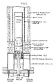
- FIGS. 1, 1A and 2 An apparatus for carrying out the method steps of this invention in a preferred embodiment is shown in FIGS. 1, 1A and 2. Reference should therefore be made to these figures and to the descriptive legends thereon in connection with the following explanation.
- the apparatus consists of a vacuum base housing on top of which is mounted an elongated vacuum chamber having a removable closure at its upper end.
- a cylindrical crucible which may be formed of alumina or other suitable refractory material.
- An openable closure is provided for the outlet port, comprising in this embodiment the lower end of a thermocouple protection tube which may be formed of alumina or other refractory material.
- thermocouple tube As shown in FIG. 1, in its lower port-closing position, the end of the thermocouple tube is received in the top of the crucible outlet.
- the bottom end of the thermacouple tube may be rounded or otherwise adjusted for sealing insertion in the port.
- an operator rod Connected to the upper end of the thermocouple tube is an operator rod, which slidably extends through an O-ring equipped vacuum seal in the top closure of the vacuum chamber. When the operator rod is lifted, as shown in FIG. 1A, the crucible outlet port is opened for discharge of the melt.
- an induction coil to which a low frequency alternating current is supplied.
- the induction coil susceptor which may be formed of tantalum, for heating the crucible.
- the susceptor and crucible are insulated for retaining heat.
- refractory insulating material such as porous alumina or zirconia may be used to enclose the susceptor and melt crucible.
- the base of the crucible can be supported, as shown, through insulation members resting on a tubular pedestal, which may be formed of quartz.
- the mold is preferably formed of quartz.
- the top of the mold tube is open for receiving melt from the crucible, and the bottom of the tube is closed by a heat-transfer wall.
- This wall may comprise the upper end of an inverted cup-shaped pedestal.
- Concentric inlet and outlet water tubes extend downwardly from the pedestal to provide for circulation of cooling water.
- the pedestal which may be formed of copper, together with the cooling pipe assembly, functions as a retractable support, permitting downward movement of the mold tube.
- the cooling water pipe assembly extends through a vacuum seal and is connected externally to a withdrawal mechanism.
- a resistance coil heater is positioned around the outside of the mold tube. This may be a platinum-rhodium resistance coil connected to a current source through a voltage controller.
- buttons or fingers of the magnetostrictive alloy are introduced into the crucible.
- the apparatus is then re-assembled and sealed.
- the vacuum system is started to reduce the pressure within the apparatus to a low vacuum such as 2 ⁇ 10 ⁇ 6 Torr.
- the induction coil generator is turned on at a low setting and the alloy charge is allowed to heat slowly while maintaining a vacuum level within the apparatus below at least 4 ⁇ 10 ⁇ 5Torr.
- the crucible and mold tube heaters may be turned on at the same time and heated to selected control temperatures. For example, the alloy may first be heated under vacuum to 1000°C or other selected pre-melt temperature.
- the system is then sealed off and an inert gas is introduced, preferably argon gas, which may be admitted to -20 kPa pressure. Heating of the alloy can then be continued until it melts, for example, for Terfenol at a temperature of around 1275°C.
- the thermocouple tube With the mold at the desired temperature for receiving the melt, usually at the same temperature as the melt, the thermocouple tube is lifted through the top vacuum seal by a small distance, such as about one-half inch. This permits the molten alloy to flow downwardly through the bottom outlet port.
- the mold tube is filled to the desired height, but some of the melt is retained in the crucible. Prior to the discharge of the melt from the crucible, impurities will have collected as "dross" at the top of the melt, as indicated in FIG. 1. By leaving a small portion of the melt within the crucible, as indicated in FIG. 1A, the separated impurities are retained in the crucible.
- the action of the induction coil not only melts the alloy but also provides a mixing action in the melt. In this way the homogeneity of the melt is achieved and maintained prior to its discharge from the crucible. This is especially desirable with rare earth-iron magnetostrictive alloys, which tend to separate and become non-homogeneous on melting. The alloy composition, if non-homogeneous on casting, would be very difficult to remix in the elongated mold tube.
- the bottom portion may be partially withdrawn from within the resistance coil heater.
- the base pedestal has been moved downwardly to the level of the water-cooled annulus, which may be formed of copper. Downward heat flow paths are indicated by the dotted arrow lines.
- heat can pass through the bottom wall of the mold tube into the pedestal cooling water, and also through the lower end portions of the side walls into the cooling water circulated through the surrounding annulus.
- the solid-liquid interface may be maintained at the level of porous refractory insulation above the cooling annulus.
- the support pedestal is lowered further. This facilitates additional transfer of heat through the side walls of the mold tube into the water-cooled annulus while still maintaining a downward heat flow in the unsolidified portion of the melt.
- the process is continued until ReFe2 alloy is completely solidified.
- FIG. 3 While the combination described is preferred, certain of the advantages of this invention can also be obtained by using a fixed position mold tube, as illustrated in FIG. 3.
- the mold tube is supported on a nonmovable water-cooled pedestal.
- heat is removed through the top of the pedestal. This generates the downward flow of heat, as indicated by the heat flow paths shown in FIG. 3, and generates a solid-liquid interface which progresses from the bottom of the top to the alloy melt. Cooling water is circulated through the support pedestal, as in the embodiment of the other figures.
- FIG. 4 illustrates a modification for simultaneous casting of a plurality of small diameter rods.
- Smaller quartz tubes as shown in FIG. 4, are positioned within a larger mold support tube.
- the smaller tubes may be of shorter length than the large mold tube, and a quartz funnel inserted in the top of the mold, as shown.
- the melt flows from the crucible into the quartz funnel, and then spreads outwardly through appertures in the funnel bottom passing into the tops of the smaller mold tubes.
- some melt may seep into the spaces between the tubes. This can be removed on completion of the molding operation at the same time as the molded rods are removed from the tubes. Alternately, it may be eliminated by designing the funnel to provide a pouring spout into each tube.
- the apparatus is disassembled for removal of the rods.
- the large tube or the small tubes may be square, triangular, hexagonal, etc.
- Rods of various lengths can be formed.
- an apparatus like that shown in FIGS. 1 and 2 has been used to form 32 to 38 mm diameter rods up to 175 mm long.
- a multiple mold tube arrangement like that of FIG. 4 several 8 mm diameter rods were formed by inserting small quartz tubes 8 mm internal diameter inside a larger mold tube of 32 mm diameter. It is also possible to solidify tube shapes by placing a core inside each quartz tube.
- a Terfenol-type alloy was employed. This alloy was heated by a tantalum susceptor acted on by an 8-turn induction coil powered by a 3000 Hz SCR inverter. A Norton-type AN 299A coarse-grained alumina crucible which had a 3/16 inch hole through the center of its bottom was used. Inserted in the hole was an alumina thermocouple tube of 1/4 ⁇ diameter. At the site of the thermocouple tube there was placed a Pt/Pt13Rh thermocouple for indicating the melt temperature.
- thermocouple protection tube had a rounded bottom that effectively sealed the hole in the bottom of the crucible and prevented pouring of the molten alloy before the desired time.
- the thermocouple tube was lifted at the time of casting by moving a connecting stainless steel tube through a vacuum seal on top of the cover flange of the apparatus.
- One casting mold used was a 32 mm I.D. quartz tube positioned approximately 5 inches below and centered on the hole in the bottom of the melt crucible.
- the bottom of the mold was fitted over a water-cooled copper pedestal which extended 1-1/4 up into the mold, thereby providing a bottom closure for the mold. Zirconia insulating cloth was inserted between the sides of the pedestal and the mold.
Landscapes
- Chemical & Material Sciences (AREA)
- Engineering & Computer Science (AREA)
- Crystallography & Structural Chemistry (AREA)
- Materials Engineering (AREA)
- Metallurgy (AREA)
- Organic Chemistry (AREA)
- Inorganic Chemistry (AREA)
- Manufacturing & Machinery (AREA)
- Crystals, And After-Treatments Of Crystals (AREA)
- Continuous Casting (AREA)
- Crucibles And Fluidized-Bed Furnaces (AREA)
- Manufacturing Of Magnetic Record Carriers (AREA)
- Magnetic Record Carriers (AREA)
Applications Claiming Priority (2)
| Application Number | Priority Date | Filing Date | Title |
|---|---|---|---|
| US07/025,572 US4770704A (en) | 1987-03-13 | 1987-03-13 | Continuous method for manufacturing grain-oriented magnetostrictive bodies |
| US25572 | 1987-03-13 |
Publications (3)
| Publication Number | Publication Date |
|---|---|
| EP0282059A2 true EP0282059A2 (de) | 1988-09-14 |
| EP0282059A3 EP0282059A3 (en) | 1989-04-05 |
| EP0282059B1 EP0282059B1 (de) | 1991-11-13 |
Family
ID=21826841
Family Applications (1)
| Application Number | Title | Priority Date | Filing Date |
|---|---|---|---|
| EP88103818A Expired - Lifetime EP0282059B1 (de) | 1987-03-13 | 1988-03-10 | Kontinuierliches Verfahren zur Herstellung von magnetostriktiven Körpern mit Körner-Orientierung |
Country Status (6)
| Country | Link |
|---|---|
| US (1) | US4770704A (de) |
| EP (1) | EP0282059B1 (de) |
| JP (1) | JPH0753628B2 (de) |
| CA (1) | CA1309320C (de) |
| DE (1) | DE3866132D1 (de) |
| NO (1) | NO171734C (de) |
Cited By (6)
| Publication number | Priority date | Publication date | Assignee | Title |
|---|---|---|---|---|
| EP0405362A1 (de) * | 1989-06-30 | 1991-01-02 | Nkk Corporation | Verfahren zur Herstellung eines Stabes aus einer supermagnetostriktiven Legierung |
| EP0405360A1 (de) * | 1989-06-30 | 1991-01-02 | Nkk Corporation | Verfahren zur Herstellung eines Stabes aus einer supermagnetostriktiven Legierung |
| EP0597096A1 (de) * | 1992-05-01 | 1994-05-18 | TDK Corporation | Verfahren und vorrichtung zur herstellung von magnetostriktivem material |
| US5336337A (en) * | 1991-02-05 | 1994-08-09 | Kabushiki Kaisha Toshiba | Magnetrostrictive materials and methods of making such materials |
| DE102007006731A1 (de) * | 2007-02-06 | 2008-08-07 | Forschungsverbund Berlin E.V. | Verfahren und Vorrichtung zur Herstellung von Zinkoxid-Einkristallen aus einer Schmelze |
| DE10196450B3 (de) * | 2000-07-21 | 2014-11-06 | Continental Automotive Systems, Inc. ( n. d. Ges. d. Staates Delaware ) | Metallurgische und mechanische Kompensation des Temperaturverhaltens von terbiumbasierten magnetostriktiven Legierungen der Seltenen Erden |
Families Citing this family (17)
| Publication number | Priority date | Publication date | Assignee | Title |
|---|---|---|---|---|
| US5039943A (en) * | 1990-05-08 | 1991-08-13 | Iowa State University Research Foundation, Inc. | Magnetostrictive magnetometer |
| US5111870A (en) * | 1990-10-11 | 1992-05-12 | Pcast Equipment Corporation | Top fill casting |
| US5348071A (en) * | 1990-10-11 | 1994-09-20 | Pcc Composites, Inc. | Top fill casting |
| WO1994001861A1 (en) * | 1992-07-10 | 1994-01-20 | Wangtek, Inc. | Servo controlled magnetic head positioner |
| US5491559A (en) * | 1994-11-04 | 1996-02-13 | Ohio Electronic Engravers, Inc. | Method and apparatus for engraving using a magnetostrictive actuator |
| US5731881A (en) * | 1994-11-04 | 1998-03-24 | Ohio Electronic Engravers, Inc. | Engraving method and apparatus using cooled magnetostrictive actuator |
| CA2269585A1 (en) | 1996-09-12 | 1998-03-19 | Etrema Products, Inc. | Compact actuator and controller and pumping apparatus for same |
| US6273965B1 (en) | 1996-10-18 | 2001-08-14 | Iowa State University Research Foundation, Inc. | Magnetostrictive materials and method for improving AC characteristics in same |
| US6624539B1 (en) | 1997-05-13 | 2003-09-23 | Edge Technologies, Inc. | High power ultrasonic transducers |
| US6273966B1 (en) | 1998-12-03 | 2001-08-14 | Etrema Products, Inc. | High performance rare earth-transition metal magnetostrictive materials |
| JP4151474B2 (ja) * | 2003-05-13 | 2008-09-17 | 信越半導体株式会社 | 単結晶の製造方法及び単結晶 |
| WO2006116227A2 (en) * | 2005-04-22 | 2006-11-02 | Siemens Water Technologies Holding Corp. | Vibratory mixer |
| US7344596B2 (en) * | 2005-08-25 | 2008-03-18 | Crystal Systems, Inc. | System and method for crystal growing |
| JP4528995B2 (ja) * | 2007-08-02 | 2010-08-25 | 国立大学法人東北大学 | Siバルク多結晶インゴットの製造方法 |
| US9278389B2 (en) * | 2011-12-20 | 2016-03-08 | General Electric Company | Induction stirred, ultrasonically modified investment castings and apparatus for producing |
| CN105986310B (zh) * | 2015-03-06 | 2018-06-01 | 有研稀土新材料股份有限公司 | 稀土磁致伸缩材料制备方法及稀土磁致伸缩材料 |
| WO2023158597A1 (en) * | 2022-02-15 | 2023-08-24 | LAU Superconductors Inc. | Manufacture and repair of high temperature reinforced superconductors |
Citations (3)
| Publication number | Priority date | Publication date | Assignee | Title |
|---|---|---|---|---|
| DE2745247A1 (de) * | 1977-10-07 | 1979-04-12 | Wacker Chemitronic | Verfahren und vorrichtung zur semikontinuierlichen herstellung von siliciumformkoerpern |
| US4308474A (en) * | 1979-11-14 | 1981-12-29 | The United States Of America As Represented By The Secretary Of The Navy | Rare earth-iron magnetostrictive materials and devices using these materials |
| EP0055310A1 (de) * | 1980-12-29 | 1982-07-07 | Semix Incorporated | Verfahren und Vorrichtung für das kontinuierliche Giessen von Silicium |
Family Cites Families (1)
| Publication number | Priority date | Publication date | Assignee | Title |
|---|---|---|---|---|
| US4609402A (en) * | 1985-10-28 | 1986-09-02 | Iowa State University Research Foundation, Inc. | Method of forming magnetostrictive rods from rare earth-iron alloys |
-
1987
- 1987-03-13 US US07/025,572 patent/US4770704A/en not_active Expired - Lifetime
-
1988
- 1988-03-01 CA CA000560241A patent/CA1309320C/en not_active Expired - Lifetime
- 1988-03-10 EP EP88103818A patent/EP0282059B1/de not_active Expired - Lifetime
- 1988-03-10 DE DE8888103818T patent/DE3866132D1/de not_active Expired - Lifetime
- 1988-03-11 NO NO881100A patent/NO171734C/no not_active IP Right Cessation
- 1988-03-14 JP JP63058542A patent/JPH0753628B2/ja not_active Expired - Lifetime
Patent Citations (3)
| Publication number | Priority date | Publication date | Assignee | Title |
|---|---|---|---|---|
| DE2745247A1 (de) * | 1977-10-07 | 1979-04-12 | Wacker Chemitronic | Verfahren und vorrichtung zur semikontinuierlichen herstellung von siliciumformkoerpern |
| US4308474A (en) * | 1979-11-14 | 1981-12-29 | The United States Of America As Represented By The Secretary Of The Navy | Rare earth-iron magnetostrictive materials and devices using these materials |
| EP0055310A1 (de) * | 1980-12-29 | 1982-07-07 | Semix Incorporated | Verfahren und Vorrichtung für das kontinuierliche Giessen von Silicium |
Cited By (11)
| Publication number | Priority date | Publication date | Assignee | Title |
|---|---|---|---|---|
| EP0405362A1 (de) * | 1989-06-30 | 1991-01-02 | Nkk Corporation | Verfahren zur Herstellung eines Stabes aus einer supermagnetostriktiven Legierung |
| EP0405360A1 (de) * | 1989-06-30 | 1991-01-02 | Nkk Corporation | Verfahren zur Herstellung eines Stabes aus einer supermagnetostriktiven Legierung |
| US5063986A (en) * | 1989-06-30 | 1991-11-12 | Nkk Corporation | Method for manufacturing alloy rod having giant magnetostriction |
| US5067551A (en) * | 1989-06-30 | 1991-11-26 | Nkk Corporation | Method for manufacturing alloy rod having giant magnetostriction |
| US5336337A (en) * | 1991-02-05 | 1994-08-09 | Kabushiki Kaisha Toshiba | Magnetrostrictive materials and methods of making such materials |
| US5527398A (en) * | 1991-02-05 | 1996-06-18 | Kabushiki Kaisha Toshiba | Magnetostrictive materials and methods of making such materials |
| EP0597096A1 (de) * | 1992-05-01 | 1994-05-18 | TDK Corporation | Verfahren und vorrichtung zur herstellung von magnetostriktivem material |
| EP0597096A4 (de) * | 1992-05-01 | 1996-04-17 | Tdk Corp | Verfahren und vorrichtung zur herstellung von magnetostriktivem material. |
| DE10196450B3 (de) * | 2000-07-21 | 2014-11-06 | Continental Automotive Systems, Inc. ( n. d. Ges. d. Staates Delaware ) | Metallurgische und mechanische Kompensation des Temperaturverhaltens von terbiumbasierten magnetostriktiven Legierungen der Seltenen Erden |
| DE102007006731A1 (de) * | 2007-02-06 | 2008-08-07 | Forschungsverbund Berlin E.V. | Verfahren und Vorrichtung zur Herstellung von Zinkoxid-Einkristallen aus einer Schmelze |
| DE102007006731B4 (de) * | 2007-02-06 | 2011-07-28 | Forschungsverbund Berlin e.V., 12489 | Verfahren und Vorrichtung zur Herstellung von Zinkoxid-Einkristallen aus einer Schmelze |
Also Published As
| Publication number | Publication date |
|---|---|
| JPH0753628B2 (ja) | 1995-06-07 |
| US4770704A (en) | 1988-09-13 |
| NO881100L (no) | 1988-09-14 |
| NO171734C (no) | 1993-04-28 |
| CA1309320C (en) | 1992-10-27 |
| EP0282059A3 (en) | 1989-04-05 |
| NO881100D0 (no) | 1988-03-11 |
| JPS63242442A (ja) | 1988-10-07 |
| NO171734B (no) | 1993-01-18 |
| EP0282059B1 (de) | 1991-11-13 |
| DE3866132D1 (de) | 1991-12-19 |
Similar Documents
| Publication | Publication Date | Title |
|---|---|---|
| US4770704A (en) | Continuous method for manufacturing grain-oriented magnetostrictive bodies | |
| US4609402A (en) | Method of forming magnetostrictive rods from rare earth-iron alloys | |
| EP0349904B1 (de) | Siliciumgiessvorrichtung | |
| Verhoeven et al. | Directional solidification and heat treatment of Terfenol-D magnetostrictive materials | |
| JPS63192543A (ja) | 金属の連続鋳造装置及び該装置の操作方法 | |
| WO2000026422A1 (fr) | Gallium tres pur utilise pour la preparation d'un compose semiconducteur, procede et systeme de purification du gallium | |
| US4202400A (en) | Directional solidification furnace | |
| CN102191542A (zh) | 制备高纯定向结晶多晶硅的设备及其制备方法 | |
| JPH01123021A (ja) | 希土類金属−鉄合金棒の磁気歪応答を増大するための熱処理方法 | |
| JPS5812328B2 (ja) | 分別結晶方法 | |
| US3529958A (en) | Method for the formation of an alloy composed of metals reactive in their elemental form with a melting container | |
| JP3725620B2 (ja) | 高純度銅単結晶の製造方法及び製造装置 | |
| US3156549A (en) | Method of melting silicon | |
| US3672879A (en) | Tini cast product | |
| US5253696A (en) | Method and apparatus for controlling solidification of metals and other materials | |
| CN1132955C (zh) | 规模连续生产大磁致伸缩材料的方法及装置 | |
| EP0405360A1 (de) | Verfahren zur Herstellung eines Stabes aus einer supermagnetostriktiven Legierung | |
| US3508914A (en) | Methods of forming and purifying nickel-titanium containing alloys | |
| EP0055310A1 (de) | Verfahren und Vorrichtung für das kontinuierliche Giessen von Silicium | |
| JP2554888B2 (ja) | 金属チタンの製造法 | |
| JP2022146327A (ja) | FeGa合金単結晶の製造方法 | |
| RU1649852C (ru) | Способ синтеза и наплавлени шихты германоэвлинита и устройство дл его осуществлени | |
| CN116358962A (zh) | 一种深过冷条件下CoFeNi中熵合金拉伸试样的制备方法 | |
| JPH0699226B2 (ja) | 単結晶棒の製造方法及び装置 | |
| JP2001287908A (ja) | シリコンシート製造装置及びそれによるシリコンシートを用いた太陽電池 |
Legal Events
| Date | Code | Title | Description |
|---|---|---|---|
| PUAI | Public reference made under article 153(3) epc to a published international application that has entered the european phase |
Free format text: ORIGINAL CODE: 0009012 |
|
| AK | Designated contracting states |
Kind code of ref document: A2 Designated state(s): DE FR GB SE |
|
| PUAL | Search report despatched |
Free format text: ORIGINAL CODE: 0009013 |
|
| RHK1 | Main classification (correction) |
Ipc: C30B 11/00 |
|
| AK | Designated contracting states |
Kind code of ref document: A3 Designated state(s): DE FR GB SE |
|
| 17P | Request for examination filed |
Effective date: 19890517 |
|
| 17Q | First examination report despatched |
Effective date: 19901129 |
|
| GRAA | (expected) grant |
Free format text: ORIGINAL CODE: 0009210 |
|
| RAP1 | Party data changed (applicant data changed or rights of an application transferred) |
Owner name: IOWA STATE UNIVERSITY RESEARCH FOUNDATION, INC. |
|
| AK | Designated contracting states |
Kind code of ref document: B1 Designated state(s): DE FR GB SE |
|
| RTI2 | Title (correction) | ||
| REF | Corresponds to: |
Ref document number: 3866132 Country of ref document: DE Date of ref document: 19911219 |
|
| ET | Fr: translation filed | ||
| PLBE | No opposition filed within time limit |
Free format text: ORIGINAL CODE: 0009261 |
|
| STAA | Information on the status of an ep patent application or granted ep patent |
Free format text: STATUS: NO OPPOSITION FILED WITHIN TIME LIMIT |
|
| 26N | No opposition filed | ||
| EAL | Se: european patent in force in sweden |
Ref document number: 88103818.6 |
|
| PGFP | Annual fee paid to national office [announced via postgrant information from national office to epo] |
Ref country code: FR Payment date: 19990218 Year of fee payment: 12 |
|
| PG25 | Lapsed in a contracting state [announced via postgrant information from national office to epo] |
Ref country code: FR Free format text: LAPSE BECAUSE OF NON-PAYMENT OF DUE FEES Effective date: 20001130 |
|
| REG | Reference to a national code |
Ref country code: FR Ref legal event code: ST |
|
| REG | Reference to a national code |
Ref country code: GB Ref legal event code: IF02 |
|
| PGFP | Annual fee paid to national office [announced via postgrant information from national office to epo] |
Ref country code: GB Payment date: 20070327 Year of fee payment: 20 |
|
| PGFP | Annual fee paid to national office [announced via postgrant information from national office to epo] |
Ref country code: SE Payment date: 20070328 Year of fee payment: 20 |
|
| PGFP | Annual fee paid to national office [announced via postgrant information from national office to epo] |
Ref country code: DE Payment date: 20070430 Year of fee payment: 20 |
|
| REG | Reference to a national code |
Ref country code: GB Ref legal event code: PE20 Expiry date: 20080309 |
|
| EUG | Se: european patent has lapsed | ||
| PG25 | Lapsed in a contracting state [announced via postgrant information from national office to epo] |
Ref country code: GB Free format text: LAPSE BECAUSE OF EXPIRATION OF PROTECTION Effective date: 20080309 |