EP0281372A1 - Device for detecting life of image forming process unit, opening of seal of the unit and attachement of the unit to an image forming apparatus - Google Patents
Device for detecting life of image forming process unit, opening of seal of the unit and attachement of the unit to an image forming apparatus Download PDFInfo
- Publication number
- EP0281372A1 EP0281372A1 EP88301802A EP88301802A EP0281372A1 EP 0281372 A1 EP0281372 A1 EP 0281372A1 EP 88301802 A EP88301802 A EP 88301802A EP 88301802 A EP88301802 A EP 88301802A EP 0281372 A1 EP0281372 A1 EP 0281372A1
- Authority
- EP
- European Patent Office
- Prior art keywords
- process unit
- sensor
- detecting
- developer
- life
- Prior art date
- Legal status (The legal status is an assumption and is not a legal conclusion. Google has not performed a legal analysis and makes no representation as to the accuracy of the status listed.)
- Granted
Links
Images


Classifications
-
- G—PHYSICS
- G03—PHOTOGRAPHY; CINEMATOGRAPHY; ANALOGOUS TECHNIQUES USING WAVES OTHER THAN OPTICAL WAVES; ELECTROGRAPHY; HOLOGRAPHY
- G03G—ELECTROGRAPHY; ELECTROPHOTOGRAPHY; MAGNETOGRAPHY
- G03G21/00—Arrangements not provided for by groups G03G13/00 - G03G19/00, e.g. cleaning, elimination of residual charge
- G03G21/16—Mechanical means for facilitating the maintenance of the apparatus, e.g. modular arrangements
- G03G21/18—Mechanical means for facilitating the maintenance of the apparatus, e.g. modular arrangements using a processing cartridge, whereby the process cartridge comprises at least two image processing means in a single unit
- G03G21/1875—Mechanical means for facilitating the maintenance of the apparatus, e.g. modular arrangements using a processing cartridge, whereby the process cartridge comprises at least two image processing means in a single unit provided with identifying means or means for storing process- or use parameters, e.g. lifetime of the cartridge
- G03G21/1878—Electronically readable memory
- G03G21/1882—Electronically readable memory details of the communication with memory, e.g. wireless communication, protocols
- G03G21/1885—Electronically readable memory details of the communication with memory, e.g. wireless communication, protocols position of the memory; memory housings; electrodes
-
- G—PHYSICS
- G03—PHOTOGRAPHY; CINEMATOGRAPHY; ANALOGOUS TECHNIQUES USING WAVES OTHER THAN OPTICAL WAVES; ELECTROGRAPHY; HOLOGRAPHY
- G03G—ELECTROGRAPHY; ELECTROPHOTOGRAPHY; MAGNETOGRAPHY
- G03G15/00—Apparatus for electrographic processes using a charge pattern
- G03G15/06—Apparatus for electrographic processes using a charge pattern for developing
- G03G15/08—Apparatus for electrographic processes using a charge pattern for developing using a solid developer, e.g. powder developer
- G03G15/0822—Arrangements for preparing, mixing, supplying or dispensing developer
- G03G15/0848—Arrangements for testing or measuring developer properties or quality, e.g. charge, size, flowability
- G03G15/0849—Detection or control means for the developer concentration
- G03G15/0853—Detection or control means for the developer concentration the concentration being measured by magnetic means
-
- G—PHYSICS
- G03—PHOTOGRAPHY; CINEMATOGRAPHY; ANALOGOUS TECHNIQUES USING WAVES OTHER THAN OPTICAL WAVES; ELECTROGRAPHY; HOLOGRAPHY
- G03G—ELECTROGRAPHY; ELECTROPHOTOGRAPHY; MAGNETOGRAPHY
- G03G15/00—Apparatus for electrographic processes using a charge pattern
- G03G15/06—Apparatus for electrographic processes using a charge pattern for developing
- G03G15/08—Apparatus for electrographic processes using a charge pattern for developing using a solid developer, e.g. powder developer
- G03G15/0822—Arrangements for preparing, mixing, supplying or dispensing developer
- G03G15/0848—Arrangements for testing or measuring developer properties or quality, e.g. charge, size, flowability
- G03G15/0856—Detection or control means for the developer level
-
- G—PHYSICS
- G03—PHOTOGRAPHY; CINEMATOGRAPHY; ANALOGOUS TECHNIQUES USING WAVES OTHER THAN OPTICAL WAVES; ELECTROGRAPHY; HOLOGRAPHY
- G03G—ELECTROGRAPHY; ELECTROPHOTOGRAPHY; MAGNETOGRAPHY
- G03G15/00—Apparatus for electrographic processes using a charge pattern
- G03G15/06—Apparatus for electrographic processes using a charge pattern for developing
- G03G15/08—Apparatus for electrographic processes using a charge pattern for developing using a solid developer, e.g. powder developer
- G03G15/0822—Arrangements for preparing, mixing, supplying or dispensing developer
- G03G15/0877—Arrangements for metering and dispensing developer from a developer cartridge into the development unit
- G03G15/0881—Sealing of developer cartridges
- G03G15/0882—Sealing of developer cartridges by a peelable sealing film
-
- G—PHYSICS
- G03—PHOTOGRAPHY; CINEMATOGRAPHY; ANALOGOUS TECHNIQUES USING WAVES OTHER THAN OPTICAL WAVES; ELECTROGRAPHY; HOLOGRAPHY
- G03G—ELECTROGRAPHY; ELECTROPHOTOGRAPHY; MAGNETOGRAPHY
- G03G21/00—Arrangements not provided for by groups G03G13/00 - G03G19/00, e.g. cleaning, elimination of residual charge
- G03G21/16—Mechanical means for facilitating the maintenance of the apparatus, e.g. modular arrangements
- G03G21/1642—Mechanical means for facilitating the maintenance of the apparatus, e.g. modular arrangements for connecting the different parts of the apparatus
- G03G21/1647—Mechanical connection means
-
- G—PHYSICS
- G03—PHOTOGRAPHY; CINEMATOGRAPHY; ANALOGOUS TECHNIQUES USING WAVES OTHER THAN OPTICAL WAVES; ELECTROGRAPHY; HOLOGRAPHY
- G03G—ELECTROGRAPHY; ELECTROPHOTOGRAPHY; MAGNETOGRAPHY
- G03G21/00—Arrangements not provided for by groups G03G13/00 - G03G19/00, e.g. cleaning, elimination of residual charge
- G03G21/16—Mechanical means for facilitating the maintenance of the apparatus, e.g. modular arrangements
- G03G21/1642—Mechanical means for facilitating the maintenance of the apparatus, e.g. modular arrangements for connecting the different parts of the apparatus
- G03G21/1652—Electrical connection means
-
- G—PHYSICS
- G03—PHOTOGRAPHY; CINEMATOGRAPHY; ANALOGOUS TECHNIQUES USING WAVES OTHER THAN OPTICAL WAVES; ELECTROGRAPHY; HOLOGRAPHY
- G03G—ELECTROGRAPHY; ELECTROPHOTOGRAPHY; MAGNETOGRAPHY
- G03G21/00—Arrangements not provided for by groups G03G13/00 - G03G19/00, e.g. cleaning, elimination of residual charge
- G03G21/16—Mechanical means for facilitating the maintenance of the apparatus, e.g. modular arrangements
- G03G21/18—Mechanical means for facilitating the maintenance of the apparatus, e.g. modular arrangements using a processing cartridge, whereby the process cartridge comprises at least two image processing means in a single unit
- G03G21/1875—Mechanical means for facilitating the maintenance of the apparatus, e.g. modular arrangements using a processing cartridge, whereby the process cartridge comprises at least two image processing means in a single unit provided with identifying means or means for storing process- or use parameters, e.g. lifetime of the cartridge
- G03G21/1878—Electronically readable memory
- G03G21/1892—Electronically readable memory for presence detection, authentication
-
- G—PHYSICS
- G03—PHOTOGRAPHY; CINEMATOGRAPHY; ANALOGOUS TECHNIQUES USING WAVES OTHER THAN OPTICAL WAVES; ELECTROGRAPHY; HOLOGRAPHY
- G03G—ELECTROGRAPHY; ELECTROPHOTOGRAPHY; MAGNETOGRAPHY
- G03G2221/00—Processes not provided for by group G03G2215/00, e.g. cleaning or residual charge elimination
- G03G2221/16—Mechanical means for facilitating the maintenance of the apparatus, e.g. modular arrangements and complete machine concepts
- G03G2221/163—Mechanical means for facilitating the maintenance of the apparatus, e.g. modular arrangements and complete machine concepts for the developer unit
-
- G—PHYSICS
- G03—PHOTOGRAPHY; CINEMATOGRAPHY; ANALOGOUS TECHNIQUES USING WAVES OTHER THAN OPTICAL WAVES; ELECTROGRAPHY; HOLOGRAPHY
- G03G—ELECTROGRAPHY; ELECTROPHOTOGRAPHY; MAGNETOGRAPHY
- G03G2221/00—Processes not provided for by group G03G2215/00, e.g. cleaning or residual charge elimination
- G03G2221/16—Mechanical means for facilitating the maintenance of the apparatus, e.g. modular arrangements and complete machine concepts
- G03G2221/1648—Mechanical means for facilitating the maintenance of the apparatus, e.g. modular arrangements and complete machine concepts using seals, e.g. to prevent scattering of toner
-
- G—PHYSICS
- G03—PHOTOGRAPHY; CINEMATOGRAPHY; ANALOGOUS TECHNIQUES USING WAVES OTHER THAN OPTICAL WAVES; ELECTROGRAPHY; HOLOGRAPHY
- G03G—ELECTROGRAPHY; ELECTROPHOTOGRAPHY; MAGNETOGRAPHY
- G03G2221/00—Processes not provided for by group G03G2215/00, e.g. cleaning or residual charge elimination
- G03G2221/16—Mechanical means for facilitating the maintenance of the apparatus, e.g. modular arrangements and complete machine concepts
- G03G2221/1651—Mechanical means for facilitating the maintenance of the apparatus, e.g. modular arrangements and complete machine concepts for connecting the different parts
- G03G2221/1657—Mechanical means for facilitating the maintenance of the apparatus, e.g. modular arrangements and complete machine concepts for connecting the different parts transmitting mechanical drive power
-
- G—PHYSICS
- G03—PHOTOGRAPHY; CINEMATOGRAPHY; ANALOGOUS TECHNIQUES USING WAVES OTHER THAN OPTICAL WAVES; ELECTROGRAPHY; HOLOGRAPHY
- G03G—ELECTROGRAPHY; ELECTROPHOTOGRAPHY; MAGNETOGRAPHY
- G03G2221/00—Processes not provided for by group G03G2215/00, e.g. cleaning or residual charge elimination
- G03G2221/16—Mechanical means for facilitating the maintenance of the apparatus, e.g. modular arrangements and complete machine concepts
- G03G2221/1651—Mechanical means for facilitating the maintenance of the apparatus, e.g. modular arrangements and complete machine concepts for connecting the different parts
- G03G2221/166—Electrical connectors
-
- G—PHYSICS
- G03—PHOTOGRAPHY; CINEMATOGRAPHY; ANALOGOUS TECHNIQUES USING WAVES OTHER THAN OPTICAL WAVES; ELECTROGRAPHY; HOLOGRAPHY
- G03G—ELECTROGRAPHY; ELECTROPHOTOGRAPHY; MAGNETOGRAPHY
- G03G2221/00—Processes not provided for by group G03G2215/00, e.g. cleaning or residual charge elimination
- G03G2221/16—Mechanical means for facilitating the maintenance of the apparatus, e.g. modular arrangements and complete machine concepts
- G03G2221/1663—Mechanical means for facilitating the maintenance of the apparatus, e.g. modular arrangements and complete machine concepts having lifetime indicators
-
- G—PHYSICS
- G03—PHOTOGRAPHY; CINEMATOGRAPHY; ANALOGOUS TECHNIQUES USING WAVES OTHER THAN OPTICAL WAVES; ELECTROGRAPHY; HOLOGRAPHY
- G03G—ELECTROGRAPHY; ELECTROPHOTOGRAPHY; MAGNETOGRAPHY
- G03G2221/00—Processes not provided for by group G03G2215/00, e.g. cleaning or residual charge elimination
- G03G2221/16—Mechanical means for facilitating the maintenance of the apparatus, e.g. modular arrangements and complete machine concepts
- G03G2221/18—Cartridge systems
- G03G2221/183—Process cartridge
- G03G2221/1892—Presence detection
Definitions
- the present invention relates to a process unit constituting a detachable part of an image forming means of an image forming apparatus such as a copying machine and the like, particularly to a device for detecting life of the process unit, and to a device for detecting opening of seal of the process unit in which developer is contained in a storage section defined by a seal member prior to use and the seal member is opened for use, and further to a device for detecting attachment of the unit to the image forming apparatus.
- Such a process unit is, as expendable, replaced by a new one for ensuring the quality of a copy image when the process unit is used up to end its life.
- a means for detecting life of the process unit and informing users of the same is known which is adapted to measure the amount of used transfer paper passing through the process unit or count the rotation number of a photosensitive drum, and give a visible indication when the obtained value reaches a predetermined value which means a predetermined life level of the process unit (see, for example, Unexamined Japanese Patent Publication No.58-152263).
- toner is consumed before visible indication of the life of the process unit is made on the basis of the counted rotation number of the drum, which makes it difficult to detect life of the process unit.
- carrier attraction occurs, that is, carrier being attracted to a latent image on the photosensitive surface, transferred onto a transfer paper, and further slipped in a fixing device, thereby giving damage to a heat roller thereof, and causing troubles in temperature control by means of a thermister.
- a process unit may be judged to lose its life due to toner consumption. In this case, however, without choosing the best timing for the judgement, the toner density cannot be accurately detected by means of a sensor, and sometimes it becomes difficult to accurately detect the life and the detection takes too much time, thereby lowering the efficiency.
- the developer is contained in a space of the developing device defined by a seal member when the process unit is in packed state prior to use, and by opening or peeling off the seal member for use i.e. at the time of installing the process unit.
- the developer is supplied into a developer chamber where a developing roller of the developing device is located so that images can be formed (see, for example, Unexamined Japanese Patent Publication No.59-61861).
- a conventional image forming apparatus is not provided with any means for detecting attachment of the process unit to the apparatus as well as detecting connection of a predetermined control system, the apparatus with the process unit being unattached still appears to be in image forming or copying state.
- a switch may be provided for detecting attachment of the process unit, which makes, however, the apparatus expensive.
- An object of the present invention is to provide a device for surely detecting the life of a process unit so that a high quality image is always formed without need of using any particular device or time.
- Another object of the present invention is to provide a device for detecting opening of a seal member of a process unit so as to prevent miscopying.
- a further object of the present invention is to provide a device for easily and inexpensively detecting attachment of a process unit to an image forming apparatus.
- the present invention provides a device for detecting life of a process unit which is detachably attached to an image forming apparatus and in which at least a developing device is included in a casing, comprising a sensor for detecting the density of toner contained in the developing device, a detecting means for detecting whether the output of the sensor is above a predetermined value after a developing roller of the developing device starts rotating and before a predetermined time lapses, and a control means for judging and issuing a signal indicating that the process unit loses its life when the output of the sensor is above the predetermined value at the time that the abovementioned predetermined time has lapsed.
- the life of the process unit is detected after developer is adequately stirred and the output of the sensor is stabilized, so that stabilized and reliable life detection can be achieved and a high quality image is always formed. And further, so-called carrier attraction can be prevented, which often occurs in a life detecting system including means for counting the rotation number of a photosensitive drum.
- a process unit including a developer storage section defined by a seal member in a part of a developing device for containing developer, whereby when using an image forming apparatus, the developer is supplied into a developer chamber in which a developing roller is located by opening the seal member, is provided with a sensor located adjacent to the developing device for detecting presence of the developer or the density of toner contained in the developer chamber, and control means for judging and issuing a signal indicating that the seal member is unopened when the output of the sensor is different from a predetermined value of the usual use state.
- the controller can judge and give the user an information that the seal member is unopened, sos that miscopying can be prevented.
- a device in yet another aspect, comprises a sensor for detecting presence of developer or the density of toner and having an output terminal which issues signals, and a control means positioned on the side of an apparatus and having an input terminal in which the sensor signals are sent, the output terminal of the sensor and the input terminal of the control means being to be connected to each other when attaching the process unit to the apparatus, and the control means judging and issuing a signal indicating that the process unit is unattached when the voltage of the input terminal thereof is different from the voltage of the usual use state.
- the attachment of the process unit can be inexpensively detected without use of any sepatate detecting switch or the like. Also, if unattached, miscopying can be prevented by calling the user's attention.
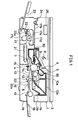
- Fig.1 illustrates the whole construction of an image forming apparatus to which a device of the present invention is attached.
- a reciprocatable original holder 2 over the upper face of a body of the image forming apparatus 1 is provided a reciprocatable original holder 2.
- an image forming process unit 3 is detachably attached to the apparatus 1.
- the process unit 3 is, as an expendable, replaced by a new one when it is used up to lose its life.
- the process unit 3 comprises a rotatable photosensitive drum 4 and a main charger 5, a developing device 6 and a cleaning device 7 arranged around the drum 4 sequentially in the direction of the rotation of the drum 4, all of which are accommodated in a casing.
- the image forming apparatus 1 has an exposure lamp 8 for exposing an original to light and a convergent light transmission member 9 by which exposed and scanned original image is focused on the photosensitive drum 4 to produce a latent electrostatic image.
- the developing device 6 though described later in detail, has developer storage sections 10a, 10b in a part of which an initial developer and supplementary toner is sealedly contained. Further, within a developer chamber 12 into which the developer is supplied from the storage section 10a or 10b by means of a supply roller 11 are provided a stirring roller 13 for stirring the developer and a developing roller 14 opposed to the photosensitive drum 4 so as to develop an latent electrostatic image on the photosensitive drum into a toner image, and the like.
- the image forming apparatus 1 further has a transfer device 15 for transferring a toner image onto transfer paper, means 16 for conveying transfer paper to a transferring section of the transfer device 15, and a fixing device 17 for fixing a transferred image on transfer paper.
- the transfer device 15 is located on the downstream side of the developing device 6 in the rotational direction of the photosensitive drum.
- the fixing device 17 is located on the downstream side of the conveying direction of the transfer paper.
- the fixing device 17 comprises a heat roller 17b provided with a heater 17a, a pressure roller 17c and a thermister 17d for controlling the temperature.
- Fig.1 are further illustrated a paper feed tray 18 located on the upstream side of the converying mean 16, a paper feed roller 19, a pair of registration rollers 20, a conveying belt 21, a paper discharge roller 22, a paper discharge tray 23, and a pivot 24 for pivotally supporting an upper casing 1a and a lower casing 1b of the image forming apparatus 1 at one end thereof so that the upper casing 1a can be opened about the pivot 24 for maintenance and examination of the apparatus 1.
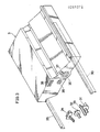
- control means comprising a microcomputer and others for controlling image forming operations of the apparatus 1, an operation and indication portion 26, a front lid 27 (Fig.2 illustrates an opened position), a pull 28 provided on the front face of the process unit 3 for inserting the process unit 3 into the apparatus 1 and detaching it therefrom in the directions of the arrow illustrated in Fig.2, and rails 29, 30 provided in the apparatus 1 for guiding the process unit 3 so as to be inserted into and detached from the apparatus 1.
- control means comprising a microcomputer and others for controlling image forming operations of the apparatus 1, an operation and indication portion 26, a front lid 27 (Fig.2 illustrates an opened position), a pull 28 provided on the front face of the process unit 3 for inserting the process unit 3 into the apparatus 1 and detaching it therefrom in the directions of the arrow illustrated in Fig.2, and rails 29, 30 provided in the apparatus 1 for guiding the process unit 3 so as to be inserted into and detached from the apparatus 1.
- Fig.3 illustrates the rear part of the process unit 3.
- a coupling 31 for a drive shaft of the drum 4 a coupling 32 for a drive shaft of the developing roller 14, a terminal 33 for supplying power to the main charger 5, and a connector 34 for receiving signals from a sensor for detecting the density of toner contained in the developing device 6.
- a coupling 35 for the shaft of the drum 4 a coupling 36 for the shaft of the developing roller 14, a connector 37 for the main charger 5 and a connector 38 for the sensor. Accordingly, all the abovementioned elements are connected with one another by attaching the process unit 3 to the apparatus 1.
- Fig.4 illustrates the process unit 3.
- containers 62a, 62b constituting the developer storage sections 10a, 10b.
- Initial developer in the developer storage section 10a is supplied into the developer chamber 12 of the casing 61.
- Supplementory toner in the developer storage section 10b is supplied into the developer chamber 12 by means of the supply roller 11.
- a toner density sensor 65 comprising magnetic permeability sensor or the like for detecting the toner density of developer contained in the developing device 6.
- the control means 25 controls, according to the output of the sensor 65, the rotation of the supply roller 11 so as to obtain the peredetermined density of toner contained in the developing device 6.
- Numeral 68 indicates a header for regulating the hight of developer on the developing roller 14.
- Numeral 69 indicates a guide plate for helping circulating of developer.
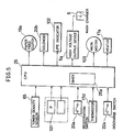
- Fig.5 illustrates a construction of the main part of a device for detecting the life of the process unit 3.
- the control means 25 includes CPU for performing a given calculation and control and a timer 25a.
- the control means 25 receives signals from the toner desity sensor 65, a print key 101, a registeration switch 20a for detecting that the leading edge of transfer paper is fed to the pair of registration rollers 20 by the paper feed roller 19 (refered to as first paper feeding hereinafter), and the thermister 17d respectively.
- control means 25 sends signals in a predetermined timing mentioned below to a paper feed clutch 19a for switching on the paper feed roller 19, a solenoid 20b for driving the pair of registration rollers 20, a life indicator 102, a high voltage output device 5a for energizing the main charger 5, a main motor 103 functioning as a driving source of the drum 4 and the developing roller 14, and the heater 17a.
- Figs.6A. 6B. 7 are flow charts showing the operation of the control means 25, and the operation will be now described below in accordance with the flow charts.
- Step S1 the power source is switched on.
- the fixing heater 17a is then turned on (Step S1) and the developing roller 14 starts rotating (Step S2), and a delay time required for stabilizing the output of the sensor 65 is held by a timer (Step S3).
- Step S3 a delay time required for stabilizing the output of the sensor 65 is held by a timer.
- Step S4 it is judged based on a detecting signal from the sensor 65 whether the process unit 3 loses its life.
- the judgement is continued till the temperature of the fixing unit is stabilized (Step S5).
- the judgement on whether the process unit loses its life is executed based on whether the output voltage of the sensor 65 is above a predetermined value. This judgement depends upon the fact that when toner contained in the process unit is consumed, the toner density of the developer (T/D) lowers and the output voltage of the sensor 65 rises.
- Step S20 When it is judged that the process unit 3 loses its life at Step S4, copying is prohibitted (Step S20), the rotation of the developing roller 14 being stopped (Step S21), the end of life of the process unit 3 being indicated on a life indicator 102 (Step S22), input acceptance of respective key being suspended (Step S23). Subsequently, the operation completes.
- Step S5 When the process unit 3 still has life, after the abovementioned Step S5, the fixing heater 17a is turned off (Step S6), the rotation of the developing roller 14 being stopped (Step S7). This state is held till the print key 101 is turned on (Step S8).
- Step S9 When the print key 101 is turned on, by turning on the paper feed clutch 19a to drive the paper feed roller 19, the first paper feeding is started (Step S9). Then the developing roller 14 starts rotating (Step S10), and thereafter it is judged based on a detecting signal from the sensor 65 whether the process unit 3 loses its life (Step S11).
- Step S24 The abovementioned judgement is continued till the first paper feeding is completed (Step S24), and before that, when the output voltage of the sensor 65 lowers below the predetermined value, it is judged that the process unit 3 does not reach its life and usual copying operation is started (Steps S12 to S19).
- Step S25 When the output voltage of the sensor 65 is still above the predetermined value at the end of the first paper feeding, the second paper feeding for feeding transfer paper from the pair of registration rollers 20 to the transferring position is not immediately started but the start thereof is delayed for a few seconds (Step S25). This delay is made with the use of the timer 25a in the control means. In the delay time, it is judged again whether the process unit 3 loses its life (Steps S26, S27).
- Step S12 When the output voltage of the sensor 65 is below the predetermined value, the ordinary copying operation (Steps S12 to S19) is started in the similar manner as abovementioned. That is, the main charger 5 is turned on (Step S12), and the pair of registration rollers 20 are driven to start the second paper feeding (Step S13). Further, after the usual copying operation is started, the life of the process unit is successively detected depending upon the output voltage of the sensor 65 (Step 14). It is examined whether the transfer paper is completely discharged by turning on the discharge switch 22a (Step S15).
- Step S16 issue of OFF signals of the main charger 5 and the second paper feeding is observed.
- Step S17 the main charger 5 and the pair of registration rollers 20 for the second paper feeding are turned off (Step S17) and then the operation is returned to the abovementioned Step S14.
- Step S15 When the discharge of transfer paper is completed at Step S15, it is judged whether the copying is continuous one or not (Step S18). If continuous copying, the operation is returned to Step S9. If not, the rotation of the developing roller 14 is stopped (Step S19), and the operation is returned to Step S8, and thereafter the same routine is repeated.
- Step S27 when the output voltage of the sensor 65 is above the predetermine value at the end of the delayed time Step S27, it is judged that the process unit loses its life, and then the operation is changed to the steps shown in Fig.7.
- the main charger 5 is not driven but remains in OFF state in order to prevent so-called carrier attraction (Step S28). Paper is discharged (Step S29).
- the end of life of the process unit 3 is indicated on the life indicater 102 (Step S30).
- the driving of the developing roller 14 is stopped (Step S31). Input acceptance of respective key is suspended (Step S32).
- Steps S 28 to S32 prevent the carrier attraction, giving no damage to the fixing device 17, further preventing jam of transfer sheet in the conveying means. Also, the user can be informed that the process unit 3 has to be renewed.
- an output curve of the sensor 65 is shown as a characteristic of toner density in Fig.8.
- the graph indicates that in lapse of time from the start of the rotation of the developing roller 14, the output voltage lowers and comes to a stabilized state. Consequently, as abovementioned, by delaying the timing of the detection at Steps S3 to S5 or by delaying the start of the second paper feeding at Steps S25 to S 27, and by detecting the output voltage of the sensor 65 in this delay time, the life level of the process unit 3 can be judged with the output voltage of the sensor 65 being stabilized, whereby the accuracy and reliability of the judgement is improved. Further, for accurately detecting the toner density by means of the sensor 65, the detection is carried out necessarily with the developing roller 14 being rotated. This requirement is also satisfied.
- the life level of the process unit 3 is detected after switching on the power source and before turning on the print key as mentioned above. Consequently, when it is judged that the process unit 3 loses its life at this stage, the operation is changed to the state of prohibiting copying. Consequently, the first paper feeding which is to be started by turning on the print key and the succeeding operation are avoided. Accordingly, loses of transfer paper can be prevented.
- the output voltage of the sensor 65 is detected during the first paper feeding at Steps S11 and S24, no waiting time is needed for the detection. Accordingly, the copying efficiency can be improved. Also, the life of the process unit 3 is detected at Step S 14 after the operation is changed to the second paper feeding and during the usual copying operation. Consequently, if the process unit 3 loses its life during the copying operation, any occurrence of the abovementioned carrier attraction can be prevented because of the turning-off of the main charger.
- the life of the process unit 3 can be detected at the following three timings; during the delayed time of the first and second feeding, after the turning-on of the print key; after switching on the power source and before turning on the print key; in the usual copying operation after the second paper feeding. It will be noted, however, that the detection need not necessarily made at all the timings. It is required only that the detection is executed in one of the following two times; the time that after the start of the rotation of the developing roller 14 and before the end of the first paper feeding; the time that the start of the second paper feeding is delayed. Accurate life detection can be similarly achieved even at each time.
- time of detecting life is mentioned the time required to stabilize the fixing device 17 and the time required to complete the first paper feeding.
- time may be obtained from detecting signal level of the thermister 17d or signal from the registration switch 20a.
- time may be obtained from a delayed time of timer on the basis of the times of turning on the print key, starting the first paper feeding, and starting the rotation of the developing roller and the like.
- process unit 3 of the abovementioned embodiment carries a photosensitive drum 4, the developing device 6, the cleaning device 7 and the like, all the components being placed in one casing. However, it is satisfactory that only the developing device 6 is provided.
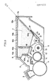
- Fig.9 mainly illustrates developing device 6 of process unit 3.
- the upper part of casing 61 of developing device 6 is attached with containers 62a, 62b constituting the developer storage sections 10a, 10b. Downward openings of containers 62a, 62b are sealed by means of seal member 63 before use. That is, one end portion 63a of the seal member 63 is stuck to one edge of one container 62b, and an intermediate portion 63b is stuck to one edge of the other container 62a and is then folded back so that the other end portion 63c is passed through a slit 3a provided in the process unit 3 to the outside.
- the other end portion 63c of the seal member 63 is pealed off in the direction of the arrow in Fig.4. Subsequently, the seal is opened and initial developer D in the developer storage section 10a is supplied into the developer chamber 12 while toner T is supplied from the developer storage section 10b into a hopper 64 provided with the supply roller 11.
- the sensor 65 including a magnetic permeability sensor for detecting the toner density of developer contained in the developing device 6.
- the control means 25 controls the rotation of the supply roller 11 according to the output of the sensor 65 so that the density of toner contained in the developing device 6 comes to a predetermined value.
- the sensor 65 detects the toner density of developer passing in front of the sensor 65. Specifically, the ratio of a toner amount to a total amount of toner and carrier (T/D) is detected in the case of two component developer. In the usual use state (e.g. T/D being 4.5% to 2%), because carrier is added, the sensor 65 outputs a level of voltage (e.g. 1V to 4V).
- T/D the ratio of a toner amount to a total amount of toner and carrier
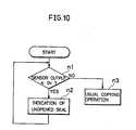
- Step n1 the power source is switched on. Then, it is judged whether the output voltage of the sensor 65 is nearly 0V (Step n1). When the answer is YES, it is judged that the seal is unopened, which is indicated at Step n2. This can be realized by making a suitable indication on the operation and indication portion 26 so as to call the user"s attention. On the other hand, when the answer is NO, it is judged that the apparatus is in the usual state and the operation is changed to the usual copying operation. The judgement that developer is consumed and not left in the developer chamber (i.e. it is time to renew the process unit 3) can be made by detecting that the output voltage of the sensor 65 reaches a predetermined value (e.g. 4V) for preventing the degradation of the image quality.
- a predetermined value e.g. 4V
- the abovementioned judgement on whether the seal is opened is preferably made before the first paper feeding is started by turning on the print key.
- the toner control sensor 65 which is a conventional sensor. In other words, it is not required to make a particular sensor for executing this operation. Consequently a reduced cost is obtained.
- two component developer is used and a sensor signal from the toner control sensor 65 is used.
- the present invention is not limited to the abovementioned embodiment.
- a level sensor or a pressure sensor is used which can detect the presence of developer in the developer chamber 12 and can output in the form of analog signals. Subsequently, unopening of the seal can be detected according to the sensor signals. When the seal is unopened, the output of sensors is 0V or nearly 0V.
- the output of the sensor for judging that developer is consumed and not left in the developer chamber is set at a higher value than that of the judgement of unopening of the seal. Accordingly, the difference between the output voltages makes it possible to distinguish unopening of the seal from consumption-up of developer.
- the output voltage of the sensor is changed when the seal member 63 is peeled off by sticking a magnetic piece to a portion of the seal member 63 and placing the seal member in such a manner that the magnetic piece is positioned in front of the toner control sensor 65, though not illustrated. This is because the magnetic piece in front of the sensor 65 is removed away. Accordingly, opening of the seal can be also detected in this way.
- Figs.11, 12 illustrate a construction of the present invention for detecting attachment of the process unit 3 to the image forming apparatus 1.
- Vcc e.g. 5V
- the output terminal of the sensor 65 is connected to the input terminal 25a of the control means 25 by the connecters 38, 34. Then, the sensor 65 located adjacent to the developing device 6 detects the toner density of the developer passing in front of the sensor 65, that is, the ratio of a toner amount to a total whole amount of carrier and toner (T/D) when two component developer is used. In the usual use state (e.g. T/D being 4.5% to 2%), the sensor 65 outputs a level of voltage (e.g. 1V to 4V) due to the presence of carrier.
- a level of voltage e.g. 1V to 4V
- the voltage level of the input terminal 25a of the control means 25 is the same as the output level of the sensor 65, though somewhat influenced by a bias potential due to the presence of the resistance R. It will be noted that when using the resistance R having a high impedance, such an influence is almost removed. In other words, there is a difference between a potential level of the input terminal 25a of the control means 25 when the process unit 3 is attached to the apparatus and a potential level it is not attached thereto. Consequently, when the voltage of the input terminal 25a of the control means 25 (0V to 4V or 4V to 5V) is different from the voltage level of the use state (e.g. 1V to 4V), the control means 25 can judge that the process unit 3 is not attached to the apparatus 1.
- Step n11 the power source is switched on. Then, it is judged whether the output voltage of the sensor 65 is Vcc (or Vss) or not (Step n11). When the answer is YES, the process unit 3 is judged to be unattached, which is indicated at Step n12. This can be realized by making a suitable indication on the operation and indication portion 26 so as to call user's attention. For the purpose of more surely calling user's attention, besides making such an indication, the image forming operation may be stopped. On the other hand, when the answer is NO, it is judged that the process unit is attached to the apparatus 3 and the operation is changed to the usual copying operation (Step n13). The judgement that developer in the developer chamber is consumed up (i.e. it is the time to renew the process unit 3) can be made by detecting that the output voltage of the sensor 65 reaches a predetermined level (e.g. 4V for preventing the degradation of the image quality).
- a predetermined level e.g. 4V for preventing
- the potential Vcc or Vss to which the input terminal 25a of the control means 25 is connected by the resistance R, is needed to set at a value different from the output level of the sensor 65 of the usual use state.
- the control means 25 includes a microcomputer
- the input terminal is usually provided with an A/D converting circuit.
- an unstabilized voltage though of a slight amount, caused due to a remaining charge of a capacitor of this circuit has an influence when no circuit is connected to the input terminal 25a.
- connection of the input terminal 25a to a potential of a predetermined voltage level by the resistance R eliminates the abovementioned influence. Consequently, unattachment of the process unit 3 can be accurately detected.
- unattachment of the process unit 3 can be detected by using a level sensor, a pressure sensor or the like as abovementioned as well as the toner control sensor 65.
- the potential of the input terminal 25a is Vcc or Vss when the process unit is unattached.
- the output level used for judging that the developer in the developer chamber is consumed up is set at a predetermined value different from Vcc or Vss. Consequently, such a difference between two potentials of the input terminal 25a makes it possible to distinguish unattachment of the process unit 3 from consumption-up of developer.
Landscapes
- Physics & Mathematics (AREA)
- General Physics & Mathematics (AREA)
- Engineering & Computer Science (AREA)
- Computer Vision & Pattern Recognition (AREA)
- Computer Networks & Wireless Communication (AREA)
- Dry Development In Electrophotography (AREA)
- Control Or Security For Electrophotography (AREA)
Abstract
Description
- The present invention relates to a process unit constituting a detachable part of an image forming means of an image forming apparatus such as a copying machine and the like, particularly to a device for detecting life of the process unit, and to a device for detecting opening of seal of the process unit in which developer is contained in a storage section defined by a seal member prior to use and the seal member is opened for use, and further to a device for detecting attachment of the unit to the image forming apparatus.
- It is conventionally known that for the purpose of facilitating maintenance and exchange of expendable parts and the like of an image forming apparatus using an electrographic system etc., a part or the whole of the image forming apparatus comprising a photosensitive drum, a developing device, a cleaning device and the like are integrated to form a process unit which is detachably attached to the image forming apparatus (see, for example, Unexamined Japanese Patent Publication No.56-128958).
- Such a process unit is, as expendable, replaced by a new one for ensuring the quality of a copy image when the process unit is used up to end its life. Then, a means for detecting life of the process unit and informing users of the same is known which is adapted to measure the amount of used transfer paper passing through the process unit or count the rotation number of a photosensitive drum, and give a visible indication when the obtained value reaches a predetermined value which means a predetermined life level of the process unit (see, for example, Unexamined Japanese Patent Publication No.58-152263).
- According to the abovementioned life detecting system, however, for example by making a large amount of copies of an original having a high density, toner is consumed before visible indication of the life of the process unit is made on the basis of the counted rotation number of the drum, which makes it difficult to detect life of the process unit. Besides, poor copied images are produced, and so-called carrier attraction occurs, that is, carrier being attracted to a latent image on the photosensitive surface, transferred onto a transfer paper, and further slipped in a fixing device, thereby giving damage to a heat roller thereof, and causing troubles in temperature control by means of a thermister.
- Further, in a copying machine etc. in which the density of toner contained in a developing device is detected and the amount of toner supply is controlled to obtain a given toner density, if the toner density is below a given value, a process unit may be judged to lose its life due to toner consumption. In this case, however, without choosing the best timing for the judgement, the toner density cannot be accurately detected by means of a sensor, and sometimes it becomes difficult to accurately detect the life and the detection takes too much time, thereby lowering the efficiency.
- Furthermore, in a conventional process unit in which at least a developing device is included in a casing, for the purpose of preventing the dispersion of developer held in the developing device as well as preventing the photosensitive surface from being roughened by the dispersed developer, the developer is contained in a space of the developing device defined by a seal member when the process unit is in packed state prior to use, and by opening or peeling off the seal member for use i.e. at the time of installing the process unit. the developer is supplied into a developer chamber where a developing roller of the developing device is located so that images can be formed (see, for example, Unexamined Japanese Patent Publication No.59-61861).
- In the prior art, however, since no means is provided for detecting opening of the seal member, a user sometimes forgets to peel off the seal member and the image forming operation is carried out with the seal member being still unopened. And in such a case, naturally no image is formed and transfer paper is wasted as miscopy or blank copy.
- Further, since a conventional image forming apparatus is not provided with any means for detecting attachment of the process unit to the apparatus as well as detecting connection of a predetermined control system, the apparatus with the process unit being unattached still appears to be in image forming or copying state.
- Therefore, if copying operation is carried out with a process unit being unattached, a jam of paper often occurs, and even if the paper can be passed through, naturally no image is formed, so that transfer paper is wasted as miscopy or blank copy. For eliminating such problems, a switch may be provided for detecting attachment of the process unit, which makes, however, the apparatus expensive.
- An object of the present invention is to provide a device for surely detecting the life of a process unit so that a high quality image is always formed without need of using any particular device or time.
- Another object of the present invention is to provide a device for detecting opening of a seal member of a process unit so as to prevent miscopying.
- A further object of the present invention is to provide a device for easily and inexpensively detecting attachment of a process unit to an image forming apparatus.
- The present invention provides a device for detecting life of a process unit which is detachably attached to an image forming apparatus and in which at least a developing device is included in a casing, comprising a sensor for detecting the density of toner contained in the developing device, a detecting means for detecting whether the output of the sensor is above a predetermined value after a developing roller of the developing device starts rotating and before a predetermined time lapses, and a control means for judging and issuing a signal indicating that the process unit loses its life when the output of the sensor is above the predetermined value at the time that the abovementioned predetermined time has lapsed.
- According to the present invention, the life of the process unit is detected after developer is adequately stirred and the output of the sensor is stabilized, so that stabilized and reliable life detection can be achieved and a high quality image is always formed. And further, so-called carrier attraction can be prevented, which often occurs in a life detecting system including means for counting the rotation number of a photosensitive drum.
- In another aspect according to the present invention, a process unit including a developer storage section defined by a seal member in a part of a developing device for containing developer, whereby when using an image forming apparatus, the developer is supplied into a developer chamber in which a developing roller is located by opening the seal member, is provided with a sensor located adjacent to the developing device for detecting presence of the developer or the density of toner contained in the developer chamber, and control means for judging and issuing a signal indicating that the seal member is unopened when the output of the sensor is different from a predetermined value of the usual use state.
- In this aspect of the invention, if a user forgets to open the seal when setting the process unit, the developer is not supplied into the developer chamber and the controller can judge and give the user an information that the seal member is unopened, sos that miscopying can be prevented.
- In yet another aspect, a device according to the present invention comprises a sensor for detecting presence of developer or the density of toner and having an output terminal which issues signals, and a control means positioned on the side of an apparatus and having an input terminal in which the sensor signals are sent, the output terminal of the sensor and the input terminal of the control means being to be connected to each other when attaching the process unit to the apparatus, and the control means judging and issuing a signal indicating that the process unit is unattached when the voltage of the input terminal thereof is different from the voltage of the usual use state.
- In this aspect of the invention, depending upon the fact that the voltage of the input terminal of the control means at the time that the process unit is attached to an apparatus is different from that at the time that the process unit is unattached, the attachment of the process unit can be inexpensively detected without use of any sepatate detecting switch or the like. Also, if unattached, miscopying can be prevented by calling the user's attention.
-
- Fig.1 is a schematic sectional view of an image forming apparatus to which a device according to the present invention is attached;
- Fig.2 is a perspective view of the apparatus in which an upper casing of the apparatus is opened;
- Fig.3 is a rearward perspective views of a process unit to be attached to the apparatus;
- Fig.4 is a sectional view of the process unit;
- Fig.5 is a block diagram showing a construction of the device for detecting life of the process unit;
- Fig.6A, 6B, 7 are flow charts showing operation for detecting life of the process unit;
- Fig.8 is a graph showing an output characteristic of a toner density sensor;
- Fig.9 is a partly sectional view of the process unit;
- Fig.10 is a flow chart showing operation for detecting opening of a seal member;
- Figs.11 and 12 are block diagrams showing construction of the device for detecting attachment of the process unit to the apparatus; and
- Fig.13 is a flow chart showing operation for detecting attachment of the process unit to the apparatus.
- Embodiments of the present invention will now be described below with reference to the appended drawings.
- Fig.1 illustrates the whole construction of an image forming apparatus to which a device of the present invention is attached.
- In this Figure, over the upper face of a body of the image forming apparatus 1 is provided a reciprocatable
original holder 2. Inside the apparatus 1, an image formingprocess unit 3 is detachably attached to the apparatus 1. Theprocess unit 3 is, as an expendable, replaced by a new one when it is used up to lose its life. Theprocess unit 3 comprises a rotatablephotosensitive drum 4 and amain charger 5, a developingdevice 6 and acleaning device 7 arranged around thedrum 4 sequentially in the direction of the rotation of thedrum 4, all of which are accommodated in a casing. - Further, the image forming apparatus 1 has an
exposure lamp 8 for exposing an original to light and a convergentlight transmission member 9 by which exposed and scanned original image is focused on thephotosensitive drum 4 to produce a latent electrostatic image. - The developing
device 6, though described later in detail, hasdeveloper storage sections developer chamber 12 into which the developer is supplied from thestorage section supply roller 11 are provided a stirringroller 13 for stirring the developer and a developingroller 14 opposed to thephotosensitive drum 4 so as to develop an latent electrostatic image on the photosensitive drum into a toner image, and the like. - The image forming apparatus 1 further has a
transfer device 15 for transferring a toner image onto transfer paper, means 16 for conveying transfer paper to a transferring section of thetransfer device 15, and afixing device 17 for fixing a transferred image on transfer paper. Thetransfer device 15 is located on the downstream side of the developingdevice 6 in the rotational direction of the photosensitive drum. Thefixing device 17 is located on the downstream side of the conveying direction of the transfer paper. Thefixing device 17 comprises aheat roller 17b provided with aheater 17a, apressure roller 17c and athermister 17d for controlling the temperature. - In Fig.1 are further illustrated a
paper feed tray 18 located on the upstream side of theconverying mean 16, apaper feed roller 19, a pair ofregistration rollers 20, aconveying belt 21, apaper discharge roller 22, apaper discharge tray 23, and apivot 24 for pivotally supporting anupper casing 1a and alower casing 1b of the image forming apparatus 1 at one end thereof so that theupper casing 1a can be opened about thepivot 24 for maintenance and examination of the apparatus 1. Further, there are illustrated control means (CPU) comprising a microcomputer and others for controlling image forming operations of the apparatus 1, an operation andindication portion 26, a front lid 27 (Fig.2 illustrates an opened position), apull 28 provided on the front face of theprocess unit 3 for inserting theprocess unit 3 into the apparatus 1 and detaching it therefrom in the directions of the arrow illustrated in Fig.2, andrails process unit 3 so as to be inserted into and detached from the apparatus 1. - Fig.3 illustrates the rear part of the
process unit 3. In the rear side plate (not shown) of the apparatus 1 are provided acoupling 31 for a drive shaft of thedrum 4, acoupling 32 for a drive shaft of the developingroller 14, aterminal 33 for supplying power to themain charger 5, and aconnector 34 for receiving signals from a sensor for detecting the density of toner contained in the developingdevice 6. And in corresponding to the above elements, in the rear side of theprocess unit 3, are provided acoupling 35 for the shaft of thedrum 4, acoupling 36 for the shaft of the developingroller 14, aconnector 37 for themain charger 5 and aconnector 38 for the sensor. Accordingly, all the abovementioned elements are connected with one another by attaching theprocess unit 3 to the apparatus 1. - Fig.4 illustrates the
process unit 3. In a upper portion of acasing 61 of the developingdevice 6 in theprocess unit 3, are providedcontainers developer storage sections developer storage section 10a is supplied into thedeveloper chamber 12 of thecasing 61. Supplementory toner in thedeveloper storage section 10b is supplied into thedeveloper chamber 12 by means of thesupply roller 11. Further,adjacent to the developingdevice 6 is provided atoner density sensor 65 comprising magnetic permeability sensor or the like for detecting the toner density of developer contained in the developingdevice 6. Accordingly, the control means 25 controls, according to the output of thesensor 65, the rotation of thesupply roller 11 so as to obtain the peredetermined density of toner contained in the developingdevice 6. Further in Fig.4,Numeral 68 indicates a header for regulating the hight of developer on the developingroller 14.Numeral 69 indicates a guide plate for helping circulating of developer. - Fig.5 illustrates a construction of the main part of a device for detecting the life of the
process unit 3. The control means 25 includes CPU for performing a given calculation and control and atimer 25a. The control means 25 receives signals from thetoner desity sensor 65, aprint key 101, aregisteration switch 20a for detecting that the leading edge of transfer paper is fed to the pair ofregistration rollers 20 by the paper feed roller 19 (refered to as first paper feeding hereinafter), and thethermister 17d respectively. On the other hand, the control means 25 sends signals in a predetermined timing mentioned below to a paper feed clutch 19a for switching on thepaper feed roller 19, asolenoid 20b for driving the pair ofregistration rollers 20, alife indicator 102, a highvoltage output device 5a for energizing themain charger 5, amain motor 103 functioning as a driving source of thedrum 4 and the developingroller 14, and theheater 17a. - Figs.6A. 6B. 7 are flow charts showing the operation of the control means 25, and the operation will be now described below in accordance with the flow charts.
- Firstly the power source is switched on. The fixing
heater 17a is then turned on (Step S₁) and the developingroller 14 starts rotating (Step S₂), and a delay time required for stabilizing the output of thesensor 65 is held by a timer (Step S₃). After lapse of the delayed time, it is judged based on a detecting signal from thesensor 65 whether theprocess unit 3 loses its life (Step S₄). When the process unit does not lose its life, the judgement is continued till the temperature of the fixing unit is stabilized (Step S₅). The judgement on whether the process unit loses its life is executed based on whether the output voltage of thesensor 65 is above a predetermined value. This judgement depends upon the fact that when toner contained in the process unit is consumed, the toner density of the developer (T/D) lowers and the output voltage of thesensor 65 rises. - When it is judged that the
process unit 3 loses its life at Step S₄, copying is prohibitted (Step S₂₀), the rotation of the developingroller 14 being stopped (Step S₂₁), the end of life of theprocess unit 3 being indicated on a life indicator 102 (Step S₂₂), input acceptance of respective key being suspended (Step S₂₃). Subsequently, the operation completes. - When the
process unit 3 still has life, after the abovementioned Step S₅, the fixingheater 17a is turned off (Step S₆), the rotation of the developingroller 14 being stopped (Step S₇). This state is held till theprint key 101 is turned on (Step S₈). - When the
print key 101 is turned on, by turning on the paper feed clutch 19a to drive thepaper feed roller 19, the first paper feeding is started (Step S₉). Then the developingroller 14 starts rotating (Step S₁₀), and thereafter it is judged based on a detecting signal from thesensor 65 whether theprocess unit 3 loses its life (Step S₁₁). - The abovementioned judgement is continued till the first paper feeding is completed (Step S₂₄), and before that, when the output voltage of the
sensor 65 lowers below the predetermined value, it is judged that theprocess unit 3 does not reach its life and usual copying operation is started (Steps S₁₂ to S₁₉). - When the output voltage of the
sensor 65 is still above the predetermined value at the end of the first paper feeding, the second paper feeding for feeding transfer paper from the pair ofregistration rollers 20 to the transferring position is not immediately started but the start thereof is delayed for a few seconds (Step S₂₅). This delay is made with the use of thetimer 25a in the control means. In the delay time, it is judged again whether theprocess unit 3 loses its life (Steps S₂₆, S₂₇). - When the output voltage of the
sensor 65 is below the predetermined value, the ordinary copying operation (Steps S₁₂ to S₁₉) is started in the similar manner as abovementioned. That is, themain charger 5 is turned on (Step S₁₂), and the pair ofregistration rollers 20 are driven to start the second paper feeding (Step S₁₃). Further, after the usual copying operation is started, the life of the process unit is successively detected depending upon the output voltage of the sensor 65 (Step 14). It is examined whether the transfer paper is completely discharged by turning on thedischarge switch 22a (Step S₁₅). - When it is judged that the
process unit 3 loses its life, steps mentioned below with reference to Fig.7 are carried out. On the other hand, while theprocess unit 3 still has life and the discharge of transfer paper is not completed, issue of OFF signals of themain charger 5 and the second paper feeding is observed (Step S₁₆). When the signal are issued, themain charger 5 and the pair ofregistration rollers 20 for the second paper feeding are turned off (Step S₁₇) and then the operation is returned to the abovementioned Step S₁₄. - When the discharge of transfer paper is completed at Step S₁₅, it is judged whether the copying is continuous one or not (Step S₁₈). If continuous copying, the operation is returned to Step S₉. If not, the rotation of the developing
roller 14 is stopped (Step S₁₉), and the operation is returned to Step S₈, and thereafter the same routine is repeated. - On the other hand, when the output voltage of the
sensor 65 is above the predetermine value at the end of the delayed time Step S₂₇, it is judged that the process unit loses its life, and then the operation is changed to the steps shown in Fig.7. In other words, themain charger 5 is not driven but remains in OFF state in order to prevent so-called carrier attraction (Step S₂₈). Paper is discharged (Step S₂₉). The end of life of theprocess unit 3 is indicated on the life indicater 102 (Step S₃₀). The driving of the developingroller 14 is stopped (Step S₃₁). Input acceptance of respective key is suspended (Step S₃₂). - Execution of the Steps S ₂₈ to S₃₂ prevent the carrier attraction, giving no damage to the fixing
device 17, further preventing jam of transfer sheet in the conveying means. Also, the user can be informed that theprocess unit 3 has to be renewed. - Further, an output curve of the
sensor 65 is shown as a characteristic of toner density in Fig.8. The graph indicates that in lapse of time from the start of the rotation of the developingroller 14, the output voltage lowers and comes to a stabilized state. Consequently, as abovementioned, by delaying the timing of the detection at Steps S₃ to S₅ or by delaying the start of the second paper feeding at Steps S₂₅ toS ₂₇, and by detecting the output voltage of thesensor 65 in this delay time, the life level of theprocess unit 3 can be judged with the output voltage of thesensor 65 being stabilized, whereby the accuracy and reliability of the judgement is improved. Further, for accurately detecting the toner density by means of thesensor 65, the detection is carried out necessarily with the developingroller 14 being rotated. This requirement is also satisfied. - Furthermore, the life level of the
process unit 3 is detected after switching on the power source and before turning on the print key as mentioned above. Consequently, when it is judged that theprocess unit 3 loses its life at this stage, the operation is changed to the state of prohibiting copying. Consequently, the first paper feeding which is to be started by turning on the print key and the succeeding operation are avoided. Accordingly, loses of transfer paper can be prevented. - Furthermore, since the output voltage of the
sensor 65 is detected during the first paper feeding at Steps S₁₁ and S₂₄, no waiting time is needed for the detection. Accordingly, the copying efficiency can be improved. Also, the life of theprocess unit 3 is detected atStep S ₁₄ after the operation is changed to the second paper feeding and during the usual copying operation. Consequently, if theprocess unit 3 loses its life during the copying operation, any occurrence of the abovementioned carrier attraction can be prevented because of the turning-off of the main charger. - In the abovementioned embodiment, the life of the
process unit 3 can be detected at the following three timings; during the delayed time of the first and second feeding, after the turning-on of the print key; after switching on the power source and before turning on the print key; in the usual copying operation after the second paper feeding. It will be noted, however, that the detection need not necessarily made at all the timings. It is required only that the detection is executed in one of the following two times; the time that after the start of the rotation of the developingroller 14 and before the end of the first paper feeding; the time that the start of the second paper feeding is delayed. Accurate life detection can be similarly achieved even at each time. - In the abovementioned explanation of the flow chart, as the time of detecting life is mentioned the time required to stabilize the fixing
device 17 and the time required to complete the first paper feeding. Such time may be obtained from detecting signal level of thethermister 17d or signal from theregistration switch 20a. Also, such time may be obtained from a delayed time of timer on the basis of the times of turning on the print key, starting the first paper feeding, and starting the rotation of the developing roller and the like. - Further,
process unit 3 of the abovementioned embodiment carries aphotosensitive drum 4, the developingdevice 6, thecleaning device 7 and the like, all the components being placed in one casing. However, it is satisfactory that only the developingdevice 6 is provided. - Furthermore, when it is detected that the process unit still has life before the predetermined time lapses, the operation is immediately changed to the usual copying operation. Consequently, unnecessary waiting time is not wasted and the efficiency of the image forming operation can be improved.
- Fig.9 mainly illustrates developing
device 6 ofprocess unit 3. - The upper part of casing 61 of developing
device 6 is attached withcontainers developer storage sections containers seal member 63 before use. That is, oneend portion 63a of theseal member 63 is stuck to one edge of onecontainer 62b, and anintermediate portion 63b is stuck to one edge of theother container 62a and is then folded back so that theother end portion 63c is passed through aslit 3a provided in theprocess unit 3 to the outside. - Before attaching the
process unit 3 to the apparatus 1, theother end portion 63c of theseal member 63 is pealed off in the direction of the arrow in Fig.4. Subsequently, the seal is opened and initial developer D in thedeveloper storage section 10a is supplied into thedeveloper chamber 12 while toner T is supplied from thedeveloper storage section 10b into ahopper 64 provided with thesupply roller 11. - Further, adjacent to the developing
device 6 is provided thesensor 65 including a magnetic permeability sensor for detecting the toner density of developer contained in the developingdevice 6. The control means 25 controls the rotation of thesupply roller 11 according to the output of thesensor 65 so that the density of toner contained in the developingdevice 6 comes to a predetermined value. - In Fig.9,
Numerals Numeral 68 indicates the header for regulating the height of developer on the developingroller 14.Numeral 69 indicates the guide plate for helping circulation of developer. In the abovementioned construction, thesensor 65 detects the toner density of developer passing in front of thesensor 65. Specifically, the ratio of a toner amount to a total amount of toner and carrier (T/D) is detected in the case of two component developer. In the usual use state (e.g. T/D being 4.5% to 2%), because carrier is added, thesensor 65 outputs a level of voltage (e.g. 1V to 4V). On the other hand, when no carrier is added, it outputs an extremely low voltage of nearly 0V. In the usual use state, the sensor does not output such a low voltage. When such a low output vosltage is sent to the control means 25, it is judged that any developer is not supplied into the developingdevice 6 i.e. into thedeveloper chamber 12 and theseal member 63 is unopened. The judging operation of the control means 25 will be described below with reference to the flow chart in Fig.10. - Firstly, the power source is switched on. Then, it is judged whether the output voltage of the
sensor 65 is nearly 0V (Step n₁). When the answer is YES, it is judged that the seal is unopened, which is indicated at Step n₂. This can be realized by making a suitable indication on the operation andindication portion 26 so as to call the user"s attention. On the other hand, when the answer is NO, it is judged that the apparatus is in the usual state and the operation is changed to the usual copying operation. The judgement that developer is consumed and not left in the developer chamber (i.e. it is time to renew the process unit 3) can be made by detecting that the output voltage of thesensor 65 reaches a predetermined value (e.g. 4V) for preventing the degradation of the image quality. - Further, the abovementioned judgement on whether the seal is opened is preferably made before the first paper feeding is started by turning on the print key.
- According to the abovementioned embodiment, detection that the seal is unopened is executed by the
toner control sensor 65 which is a conventional sensor. In other words, it is not required to make a particular sensor for executing this operation. Consequently a reduced cost is obtained. - Further, in the abovementioned embodiment, two component developer is used and a sensor signal from the
toner control sensor 65 is used. However, the present invention is not limited to the abovementioned embodiment. For example, when one component developer is used, a level sensor or a pressure sensor is used which can detect the presence of developer in thedeveloper chamber 12 and can output in the form of analog signals. Subsequently, unopening of the seal can be detected according to the sensor signals. When the seal is unopened, the output of sensors is 0V or nearly 0V. On the other hand, the output of the sensor for judging that developer is consumed and not left in the developer chamber is set at a higher value than that of the judgement of unopening of the seal. Accordingly, the difference between the output voltages makes it possible to distinguish unopening of the seal from consumption-up of developer. - Further, the output voltage of the sensor is changed when the
seal member 63 is peeled off by sticking a magnetic piece to a portion of theseal member 63 and placing the seal member in such a manner that the magnetic piece is positioned in front of thetoner control sensor 65, though not illustrated. This is because the magnetic piece in front of thesensor 65 is removed away. Accordingly, opening of the seal can be also detected in this way. - Figs.11, 12 illustrate a construction of the present invention for detecting attachment of the
process unit 3 to the image forming apparatus 1. Aninput terminal 25a of the control means 25 is connected to a resistance R (preferably having a high impedance) which is connected to a predetermined Vcc (e.g. 5V) potential or to Vss ( earth=0V). In the abovementioned construction, when theprocess unit 3 is not attached to the appratus, the voltage level of theinput terminal 25a of the control means 25 is Vcc or Vss. - On the other hand, whens the
process unit 3 is attached to the apparatus 1, the output terminal of thesensor 65 is connected to theinput terminal 25a of the control means 25 by theconnecters sensor 65 located adjacent to the developingdevice 6 detects the toner density of the developer passing in front of thesensor 65, that is, the ratio of a toner amount to a total whole amount of carrier and toner (T/D) when two component developer is used. In the usual use state (e.g. T/D being 4.5% to 2%), thesensor 65 outputs a level of voltage (e.g. 1V to 4V) due to the presence of carrier. Consequently, the voltage level of theinput terminal 25a of the control means 25 is the same as the output level of thesensor 65, though somewhat influenced by a bias potential due to the presence of the resistance R. It will be noted that when using the resistance R having a high impedance, such an influence is almost removed. In other words, there is a difference between a potential level of theinput terminal 25a of the control means 25 when theprocess unit 3 is attached to the apparatus and a potential level it is not attached thereto. Consequently, when the voltage of theinput terminal 25a of the control means 25 (0V to 4V or 4V to 5V) is different from the voltage level of the use state (e.g. 1V to 4V), the control means 25 can judge that theprocess unit 3 is not attached to the apparatus 1. - This judging operation of the control means 25 will be described below with reference to the flow chart in Fig.13.
- Firstly, the power source is switched on. Then, it is judged whether the output voltage of the
sensor 65 is Vcc (or Vss) or not (Step n₁₁). When the answer is YES, theprocess unit 3 is judged to be unattached, which is indicated at Step n₁₂. This can be realized by making a suitable indication on the operation andindication portion 26 so as to call user's attention. For the purpose of more surely calling user's attention, besides making such an indication, the image forming operation may be stopped. On the other hand, when the answer is NO, it is judged that the process unit is attached to theapparatus 3 and the operation is changed to the usual copying operation (Step n₁₃). The judgement that developer in the developer chamber is consumed up (i.e. it is the time to renew the process unit 3) can be made by detecting that the output voltage of thesensor 65 reaches a predetermined level (e.g. 4V for preventing the degradation of the image quality). - As abovementioned, for detecting the attachment of the
process unit 3, a particular switch for executing this operation is not required. Consequently, a reduced cost can be obtained. - It will be apparent that the potential Vcc or Vss, to which the
input terminal 25a of the control means 25 is connected by the resistance R, is needed to set at a value different from the output level of thesensor 65 of the usual use state. Further, when the control means 25 includes a microcomputer, the input terminal is usually provided with an A/D converting circuit. Subsquently, an unstabilized voltage, though of a slight amount, caused due to a remaining charge of a capacitor of this circuit has an influence when no circuit is connected to theinput terminal 25a. However, connection of theinput terminal 25a to a potential of a predetermined voltage level by the resistance R eliminates the abovementioned influence. Consequently, unattachment of theprocess unit 3 can be accurately detected. - Further, unattachment of the
process unit 3 can be detected by using a level sensor, a pressure sensor or the like as abovementioned as well as thetoner control sensor 65. The potential of theinput terminal 25a is Vcc or Vss when the process unit is unattached. On the other hand, the output level used for judging that the developer in the developer chamber is consumed up is set at a predetermined value different from Vcc or Vss. Consequently, such a difference between two potentials of theinput terminal 25a makes it possible to distinguish unattachment of theprocess unit 3 from consumption-up of developer.
Claims (11)
a sensor for detecting the density of toner contained in the developing device;
means for detecting whether the output of the sensor is above a predetermined value after a developing roller of the developing device starts rotating and before a predetermined time lapses; and
control means for changing operation to a usual image forming operation when the output of the sensor is below a predetermined value, and judging that the process unit has reached the end of its working life when the output of the sensor is above the predetermined value at the time that the predetermined time lapses with the output of the sensor not coming to a value lower than the predetermined value and issuing a signal concerning the life of the process unit accordingly.
a sensor located adjacent the developing device for detecting presence of developer or the density of toner contained in a developer chamber; and
control means for judging that the seal member is unopened when the output of the sensor is not a predetermined value corresponding to the normal use state and issuing a signal indicating non-opening of the seal accordingly.
a sensor for detecting presence of developer or the density of toner contained in the developing device and having an output terminal for issuing signals; and
control means provided in the apparatus and having an input terminal for receiving a signal from the sensor;
the output terminal of the sensor and the input terminal of the control means being connected to each other by attaching the process unit to the apparatus; and
the control means judging that the process unit is unattached when the voltage of the input terminal thereof is not the value corresponding to the normal use state and issuing a signal indicating the non-attachment of the process unit accordingly.
Applications Claiming Priority (8)
| Application Number | Priority Date | Filing Date | Title |
|---|---|---|---|
| JP49610/87 | 1987-03-03 | ||
| JP49606/87 | 1987-03-03 | ||
| JP4961087 | 1987-03-03 | ||
| JP62049607A JPH0820841B2 (en) | 1987-03-03 | 1987-03-03 | Mounting detection device for process unit |
| JP49607/87 | 1987-03-03 | ||
| JP62049606A JPH0715609B2 (en) | 1987-03-03 | 1987-03-03 | Seal open detection device for process unit |
| JP62095534A JP2689984B2 (en) | 1987-03-03 | 1987-04-17 | Process unit life detection method |
| JP95534/87 | 1987-04-17 |
Publications (2)
| Publication Number | Publication Date |
|---|---|
| EP0281372A1 true EP0281372A1 (en) | 1988-09-07 |
| EP0281372B1 EP0281372B1 (en) | 1993-08-18 |
Family
ID=27462383
Family Applications (1)
| Application Number | Title | Priority Date | Filing Date |
|---|---|---|---|
| EP88301802A Expired - Lifetime EP0281372B1 (en) | 1987-03-03 | 1988-03-02 | Device for detecting life of image forming process unit, opening of seal of the unit and attachement of the unit to an image forming apparatus |
Country Status (3)
| Country | Link |
|---|---|
| US (1) | US4873549A (en) |
| EP (1) | EP0281372B1 (en) |
| DE (1) | DE3883268T2 (en) |
Cited By (12)
| Publication number | Priority date | Publication date | Assignee | Title |
|---|---|---|---|---|
| EP0373651A2 (en) * | 1988-12-14 | 1990-06-20 | Canon Kabushiki Kaisha | Cleaning sheet for fixating rotational member and image forming apparatus having fixating rotational member |
| GB2231171A (en) * | 1989-04-19 | 1990-11-07 | Ricoh Kk | Toner supply device for electrophotographic equipment |
| EP0405522A2 (en) * | 1989-06-30 | 1991-01-02 | Mita Industrial Co., Ltd. | Developing apparatus |
| EP0600665A1 (en) * | 1992-11-30 | 1994-06-08 | Mita Industrial Co. Ltd. | Image forming machine equipped with an exchangeable developing unit |
| EP0679964A2 (en) * | 1994-04-27 | 1995-11-02 | Canon Kabushiki Kaisha | Process cartridge and image forming apparatus |
| EP0822469A1 (en) * | 1996-07-31 | 1998-02-04 | Canon Kabushiki Kaisha | Process cartridge and image forming apparatus to which process cartridge can detachably be mounted |
| EP0827048A2 (en) * | 1996-08-29 | 1998-03-04 | Canon Kabushiki Kaisha | Process cartridge, electrophotographic image forming apparatus and connecting contacts |
| US5891259A (en) * | 1997-08-18 | 1999-04-06 | No Touch North America | Cleaning method for printing apparatus |
| US5950047A (en) * | 1997-08-01 | 1999-09-07 | Canon Kabushiki Kaisha | Process cartridge, electrophotographic image forming apparatus, and electrical connection therebetween |
| EP0945768A2 (en) * | 1998-03-26 | 1999-09-29 | Canon Kabushiki Kaisha | Image forming apparatus and cartridge detachable to same |
| US6215969B1 (en) | 1994-10-17 | 2001-04-10 | Canon Kabushiki Kaisha | Toner container, toner container assembling method, process cartridge, and electrophotographic image forming apparatus |
| US6804475B2 (en) | 2001-03-09 | 2004-10-12 | Canon Kabushiki Kaisha | Process cartridge comprising grounding, charging bias, and developing bias contacts and input and output contacts, and electrophotographic image forming apparatus to which the process cartridge is detachably mountable |
Families Citing this family (34)
| Publication number | Priority date | Publication date | Assignee | Title |
|---|---|---|---|---|
| JPS6435579A (en) * | 1987-07-31 | 1989-02-06 | Toshiba Corp | Image forming device |
| JP2927808B2 (en) * | 1988-03-22 | 1999-07-28 | 株式会社日立製作所 | Electrostatic recording apparatus and photoreceptor life evaluation method |
| DE3920338A1 (en) * | 1988-06-28 | 1990-01-04 | Minolta Camera Kk | IMAGE GENERATING DEVICE WITH ACCURATE TROUBLESHOOTING |
| US4996566A (en) * | 1988-11-01 | 1991-02-26 | Konica Corporation | Multicolor image forming apparatus with separately removable and insertable assembly units |
| JPH0278963U (en) * | 1988-12-07 | 1990-06-18 | ||
| US5561787A (en) * | 1989-03-07 | 1996-10-01 | Xerox Corporation | User interface module |
| GB2234467B (en) * | 1989-07-04 | 1993-06-16 | Ricoh Kk | Image forming apparatus with replaceable process units. |
| DE4035743A1 (en) * | 1989-11-10 | 1991-05-29 | Asahi Optical Co Ltd | TONER DEFECTIVITY DETECTOR |
| JP2827137B2 (en) * | 1989-12-05 | 1998-11-18 | 株式会社リコー | Cleaner toner magazine and electrophotographic recording device |
| JP2801409B2 (en) * | 1989-12-26 | 1998-09-21 | キヤノン株式会社 | Inkjet device and recording unit cartridge |
| JP2985205B2 (en) * | 1990-01-25 | 1999-11-29 | ミノルタ株式会社 | Image forming device |
| US5028961A (en) * | 1990-08-20 | 1991-07-02 | Eastman Kodak Company | Development apparatus having a developer material storage chamber which automatically discharges upon operation of the mixer |
| US5214481A (en) * | 1992-01-31 | 1993-05-25 | Eastman Kodak Company | Image-forming apparatus having replaceable fusing roller and logic and control |
| JP3165729B2 (en) * | 1992-03-23 | 2001-05-14 | キヤノン株式会社 | Developing device and process cartridge |
| JP2669485B2 (en) * | 1992-05-22 | 1997-10-27 | ブラザー工業株式会社 | Electrophotographic equipment |
| JP3005138B2 (en) * | 1993-03-09 | 2000-01-31 | シャープ株式会社 | Developing device |
| US5331378A (en) * | 1993-07-29 | 1994-07-19 | Lexmark International, Inc. | Toner cartridge with independent driven systems |
| KR0131959B1 (en) * | 1994-11-10 | 1998-10-01 | 김광호 | Alarm method and device of process cartridge changing time |
| KR0131958B1 (en) * | 1994-11-10 | 1998-10-01 | 김광호 | Alarm method and device of process cartridge changing time |
| US5510884A (en) * | 1995-03-24 | 1996-04-23 | Xerox Corporation | Supply accessory for a printing machine with hidden identifier |
| EP0738940B1 (en) * | 1995-04-21 | 2003-07-09 | Canon Kabushiki Kaisha | Process cartridge and image forming apparatus |
| JP3445040B2 (en) * | 1995-10-09 | 2003-09-08 | キヤノン株式会社 | Image forming device |
| JP3563893B2 (en) * | 1996-10-30 | 2004-09-08 | キヤノン株式会社 | Image forming apparatus and cartridge |
| CN1138185C (en) * | 1999-01-14 | 2004-02-11 | 株式会社理光 | Method for detecting sealing component whether removed or not and image-forming device |
| JP3442047B2 (en) * | 2000-11-17 | 2003-09-02 | キヤノン株式会社 | Process cartridge and electrophotographic image forming apparatus |
| JP4906251B2 (en) * | 2003-08-29 | 2012-03-28 | 株式会社リコー | Process cartridge and image forming apparatus |
| US20060002722A1 (en) * | 2004-07-01 | 2006-01-05 | Kabushiki Kaisha Toshiba | System and method for detecting a life time of a developer |
| US7162175B2 (en) * | 2004-11-29 | 2007-01-09 | Kabushiki Kaisha Toshiba | Image forming apparatus including temperature sensor and method thereof |
| KR100727943B1 (en) * | 2005-06-27 | 2007-06-14 | 삼성전자주식회사 | Toner cartridge having the life detection board built-in and electrophotographic image forming apparatus using the same |
| JP4498407B2 (en) | 2006-12-22 | 2010-07-07 | キヤノン株式会社 | Process cartridge, electrophotographic image forming apparatus, and electrophotographic photosensitive drum unit |
| JP4948382B2 (en) | 2006-12-22 | 2012-06-06 | キヤノン株式会社 | Coupling member for mounting photosensitive drum |
| JP5311854B2 (en) | 2007-03-23 | 2013-10-09 | キヤノン株式会社 | Electrophotographic image forming apparatus, developing device, and coupling member |
| JP4558083B2 (en) | 2008-06-20 | 2010-10-06 | キヤノン株式会社 | Cartridge, method for assembling the cartridge, and method for disassembling the cartridge |
| US10527982B2 (en) | 2016-07-22 | 2020-01-07 | Hewlett-Packard Development Company, L.P. | Fuser failure prediction |
Citations (1)
| Publication number | Priority date | Publication date | Assignee | Title |
|---|---|---|---|---|
| US4538896A (en) * | 1981-03-18 | 1985-09-03 | Canon Kabushiki Kaisha | Unit for an image formation apparatus and image formation apparatus provided with the same unit |
Family Cites Families (15)
| Publication number | Priority date | Publication date | Assignee | Title |
|---|---|---|---|---|
| US4003064A (en) * | 1974-12-23 | 1977-01-11 | Polaroid Corporation | Multi-purpose film cassette processor having slideable nozzle plate |
| JPS57163276A (en) * | 1981-04-01 | 1982-10-07 | Canon Inc | Picture forming device |
| JPS57172235A (en) * | 1981-04-16 | 1982-10-23 | Olympus Optical Co Ltd | Detector for toner density |
| JPS58152263A (en) * | 1982-03-05 | 1983-09-09 | Canon Inc | Process kit and image forming device using said process kit |
| JPS5961851A (en) * | 1982-09-30 | 1984-04-09 | Canon Inc | Display mechanism for life of process cartridge |
| JPS5961861A (en) * | 1982-09-30 | 1984-04-09 | Canon Inc | Process cartridge |
| JPS5961846A (en) * | 1982-09-30 | 1984-04-09 | Canon Inc | Process cartridge and image forming device using the same |
| JPS5961850A (en) * | 1982-09-30 | 1984-04-09 | Canon Inc | Process cartridge |
| JPS59176051U (en) * | 1983-05-11 | 1984-11-24 | 京セラミタ株式会社 | Appropriate developer condition detection device for copying machines |
| US4615608A (en) * | 1983-10-31 | 1986-10-07 | Canon Kabushiki Kaisha | Developing apparatus |
| JPS60114870A (en) * | 1983-11-25 | 1985-06-21 | Canon Inc | Image forming device |
| US4669856A (en) * | 1984-09-10 | 1987-06-02 | Sharp Kabushiki Kaisha | Warning device for developer control |
| US4742372A (en) * | 1985-08-09 | 1988-05-03 | Mita Industrial Co., Ltd. | Toner detection method and device for copying machines |
| US5322813A (en) * | 1992-08-31 | 1994-06-21 | International Business Machines Corporation | Method of making supersaturated rare earth doped semiconductor layers by chemical vapor deposition |
| JP3120588B2 (en) * | 1992-09-07 | 2000-12-25 | トヨタ自動車株式会社 | Vehicle characteristic changing device |
-
1988
- 1988-02-29 US US07/161,571 patent/US4873549A/en not_active Expired - Lifetime
- 1988-03-02 EP EP88301802A patent/EP0281372B1/en not_active Expired - Lifetime
- 1988-03-02 DE DE88301802T patent/DE3883268T2/en not_active Expired - Lifetime
Patent Citations (1)
| Publication number | Priority date | Publication date | Assignee | Title |
|---|---|---|---|---|
| US4538896A (en) * | 1981-03-18 | 1985-09-03 | Canon Kabushiki Kaisha | Unit for an image formation apparatus and image formation apparatus provided with the same unit |
Non-Patent Citations (8)
| Title |
|---|
| IBM TECHNICAL DISCLOSURE BULLETIN, vol. 17, no. 4, September 1974, page 1096, New York, US; G.T. WILLIAMS: "Toner control interlocks" * |
| PATENT ABSTRACTS OF JAPAN, vol. 10, no. 247 (P-490)[2303], 26th August 1986; & JP-A-61 077 062 (CANON INC.) 19-04-1986 * |
| PATENT ABSTRACTS OF JAPAN, vol. 7, no. 274 (P-241)[1419], 7th December 1983; & JP-A-58 152 263 (CANON K.K.) 09-09-1983 (Cat. D) * |
| PATENT ABSTRACTS OF JAPAN, vol. 8, no. 165 (P-291)[1602], 31st July 1984; & JP-A-59 061 846 (CANON K.K.) 09-04-1984 * |
| PATENT ABSTRACTS OF JAPAN, vol. 8, no. 165 (P-291)[1602], 31st July 1984; & JP-A-59 061 850 (CANON K.K.) 09-04-1984 * |
| PATENT ABSTRACTS OF JAPAN, vol. 8, no. 165 (P-291)[1602], 31st July 1984; & JP-A-59 061 861 (CANON K.K.) 09-04-1984 (Cat. D) * |
| PATENT ABSTRACTS OF JAPAN, vol. 9, no. 232 (P-389)[1955], 18th September 1985; & JP-A-60 087 354 (KONISHIROKU SHASHIN KOGYO K.K.) 17-05-1985 * |
| PATENT ABSTRACTS OF JAPAN, vol. 9, no. 265 (P-399)[1988], 23rd October 1985; & JP-A-60 114 870 (CANON K.K.) 21-06-1985 * |
Cited By (27)
| Publication number | Priority date | Publication date | Assignee | Title |
|---|---|---|---|---|
| US5138390A (en) * | 1988-12-14 | 1992-08-11 | Canon Kabushiki Kaisha | Cleaning sheet for fixating rotational member and image forming apparatus having fixating rotational member |
| EP0373651A2 (en) * | 1988-12-14 | 1990-06-20 | Canon Kabushiki Kaisha | Cleaning sheet for fixating rotational member and image forming apparatus having fixating rotational member |
| EP0373651A3 (en) * | 1988-12-14 | 1991-07-17 | Canon Kabushiki Kaisha | Cleaning sheet for fixating rotational member and image forming apparatus having fixating rotational member |
| GB2231171A (en) * | 1989-04-19 | 1990-11-07 | Ricoh Kk | Toner supply device for electrophotographic equipment |
| GB2231171B (en) * | 1989-04-19 | 1993-04-14 | Ricoh Kk | Toner supply device for electrophotographic equipment |
| EP0405522A3 (en) * | 1989-06-30 | 1991-08-07 | Mita Industrial Co., Ltd. | Developing apparatus |
| EP0405522A2 (en) * | 1989-06-30 | 1991-01-02 | Mita Industrial Co., Ltd. | Developing apparatus |
| EP0600665A1 (en) * | 1992-11-30 | 1994-06-08 | Mita Industrial Co. Ltd. | Image forming machine equipped with an exchangeable developing unit |
| EP0723210A2 (en) * | 1992-11-30 | 1996-07-24 | Mita Industrial Co., Ltd. | Image forming machine equipped with an exchangeable developing unit |
| EP0723210A3 (en) * | 1992-11-30 | 1997-07-30 | Mita Industrial Co Ltd | Image forming machine equipped with an exchangeable developing unit |
| US6163660A (en) * | 1992-11-30 | 2000-12-19 | Kyocera Mita Corporation | Image-forming machine equipped with an exchangeable developing unit |
| US5873012A (en) * | 1994-04-19 | 1999-02-16 | Canon Kabushiki Kaisha | Image forming apparatus having process cartridge with specific arrangement of electrical contacts |
| US6128452A (en) * | 1994-04-27 | 2000-10-03 | Canon Kabushiki Kaisha | Process cartridge and image forming apparatus having particular arrangement of electrical contacts |
| EP0679964A2 (en) * | 1994-04-27 | 1995-11-02 | Canon Kabushiki Kaisha | Process cartridge and image forming apparatus |
| EP0679964A3 (en) * | 1994-04-27 | 1996-06-05 | Canon Kk | Process cartridge and image forming apparatus. |
| US6215969B1 (en) | 1994-10-17 | 2001-04-10 | Canon Kabushiki Kaisha | Toner container, toner container assembling method, process cartridge, and electrophotographic image forming apparatus |
| EP0822469A1 (en) * | 1996-07-31 | 1998-02-04 | Canon Kabushiki Kaisha | Process cartridge and image forming apparatus to which process cartridge can detachably be mounted |
| US5963759A (en) * | 1996-07-31 | 1999-10-05 | Canon Kabushiki Kaisha | Process cartridge and image forming apparatus to which process cartridge can detachably be mounted |
| US5926666A (en) * | 1996-08-29 | 1999-07-20 | Canon Kabushiki Kaisha | Process cartridge, electrophotographic image forming apparatus and connection method of connecting contacts |
| EP0827048A3 (en) * | 1996-08-29 | 1998-03-18 | Canon Kabushiki Kaisha | Process cartridge, electrophotographic image forming apparatus and connecting contacts |
| EP0827048A2 (en) * | 1996-08-29 | 1998-03-04 | Canon Kabushiki Kaisha | Process cartridge, electrophotographic image forming apparatus and connecting contacts |
| US5950047A (en) * | 1997-08-01 | 1999-09-07 | Canon Kabushiki Kaisha | Process cartridge, electrophotographic image forming apparatus, and electrical connection therebetween |
| US6001472A (en) * | 1997-08-18 | 1999-12-14 | No Touch North America | Cleaning sheet for printing apparatus |
| US5891259A (en) * | 1997-08-18 | 1999-04-06 | No Touch North America | Cleaning method for printing apparatus |
| EP0945768A2 (en) * | 1998-03-26 | 1999-09-29 | Canon Kabushiki Kaisha | Image forming apparatus and cartridge detachable to same |
| EP0945768A3 (en) * | 1998-03-26 | 2001-02-14 | Canon Kabushiki Kaisha | Image forming apparatus and cartridge detachable to same |
| US6804475B2 (en) | 2001-03-09 | 2004-10-12 | Canon Kabushiki Kaisha | Process cartridge comprising grounding, charging bias, and developing bias contacts and input and output contacts, and electrophotographic image forming apparatus to which the process cartridge is detachably mountable |
Also Published As
| Publication number | Publication date |
|---|---|
| US4873549A (en) | 1989-10-10 |
| DE3883268D1 (en) | 1993-09-23 |
| DE3883268T2 (en) | 1994-02-24 |
| EP0281372B1 (en) | 1993-08-18 |
Similar Documents
| Publication | Publication Date | Title |
|---|---|---|
| EP0281372A1 (en) | Device for detecting life of image forming process unit, opening of seal of the unit and attachement of the unit to an image forming apparatus | |
| KR100370539B1 (en) | Image forming apparatus and method for obtaining appropriate toner density | |
| US4913087A (en) | Developing device of a copier | |
| US5055881A (en) | Device for supplying a toner to a developing unit | |
| US4435074A (en) | Cleaning apparatus for electrophotography comprising lubricant film applicator means | |
| US4739367A (en) | Image forming apparatus having a control means for effecting control of a preliminary processing of image formation | |
| JPH04191773A (en) | Image forming device | |
| US4942431A (en) | Image forming apparatus | |
| JP3398486B2 (en) | Image forming device | |
| JPS63214766A (en) | Mounting detector for process unit | |
| EP0503913A2 (en) | An image forming apparatus | |
| JP3098568B2 (en) | Toner supply device | |
| JPH09274369A (en) | Image forming device | |
| JPH07311498A (en) | Image forming method and its control method | |
| JP3024811B2 (en) | Developing device | |
| JP2689984B2 (en) | Process unit life detection method | |
| JP2000267424A (en) | Image forming device | |
| JPH0566669A (en) | Electrophotographic copying machine | |
| JPH09274385A (en) | Image forming device | |
| JP3016736B2 (en) | Image forming device | |
| JPH09274382A (en) | Developing device and image forming device | |
| JPH031180A (en) | Adjusting method for toner concentration detecting means | |
| JPH08292637A (en) | Electrophotographic device | |
| JPH04131864A (en) | Image forming device | |
| JPS62105172A (en) | Image forming device |
Legal Events
| Date | Code | Title | Description |
|---|---|---|---|
| PUAI | Public reference made under article 153(3) epc to a published international application that has entered the european phase |
Free format text: ORIGINAL CODE: 0009012 |
|
| AK | Designated contracting states |
Kind code of ref document: A1 Designated state(s): DE FR GB NL |
|
| 17P | Request for examination filed |
Effective date: 19890110 |
|
| 17Q | First examination report despatched |
Effective date: 19910129 |
|
| GRAA | (expected) grant |
Free format text: ORIGINAL CODE: 0009210 |
|
| AK | Designated contracting states |
Kind code of ref document: B1 Designated state(s): DE FR GB NL |
|
| REF | Corresponds to: |
Ref document number: 3883268 Country of ref document: DE Date of ref document: 19930923 |
|
| ET | Fr: translation filed | ||
| PLBE | No opposition filed within time limit |
Free format text: ORIGINAL CODE: 0009261 |
|
| STAA | Information on the status of an ep patent application or granted ep patent |
Free format text: STATUS: NO OPPOSITION FILED WITHIN TIME LIMIT |
|
| 26N | No opposition filed | ||
| PGFP | Annual fee paid to national office [announced via postgrant information from national office to epo] |
Ref country code: FR Payment date: 19980310 Year of fee payment: 11 |
|
| PGFP | Annual fee paid to national office [announced via postgrant information from national office to epo] |
Ref country code: NL Payment date: 19980326 Year of fee payment: 11 |
|
| PG25 | Lapsed in a contracting state [announced via postgrant information from national office to epo] |
Ref country code: NL Free format text: LAPSE BECAUSE OF NON-PAYMENT OF DUE FEES Effective date: 19991001 |
|
| PG25 | Lapsed in a contracting state [announced via postgrant information from national office to epo] |
Ref country code: FR Free format text: LAPSE BECAUSE OF NON-PAYMENT OF DUE FEES Effective date: 19991130 |
|
| NLV4 | Nl: lapsed or anulled due to non-payment of the annual fee |
Effective date: 19991001 |
|
| REG | Reference to a national code |
Ref country code: FR Ref legal event code: ST |
|
| REG | Reference to a national code |
Ref country code: GB Ref legal event code: IF02 |
|
| PGFP | Annual fee paid to national office [announced via postgrant information from national office to epo] |
Ref country code: DE Payment date: 20070222 Year of fee payment: 20 |
|
| PGFP | Annual fee paid to national office [announced via postgrant information from national office to epo] |
Ref country code: GB Payment date: 20070228 Year of fee payment: 20 |
|
| REG | Reference to a national code |
Ref country code: GB Ref legal event code: PE20 |
|
| PG25 | Lapsed in a contracting state [announced via postgrant information from national office to epo] |
Ref country code: GB Free format text: LAPSE BECAUSE OF EXPIRATION OF PROTECTION Effective date: 20080301 |