EP0280960A2 - Pistons for internal-combustion engines - Google Patents
Pistons for internal-combustion engines Download PDFInfo
- Publication number
- EP0280960A2 EP0280960A2 EP88102287A EP88102287A EP0280960A2 EP 0280960 A2 EP0280960 A2 EP 0280960A2 EP 88102287 A EP88102287 A EP 88102287A EP 88102287 A EP88102287 A EP 88102287A EP 0280960 A2 EP0280960 A2 EP 0280960A2
- Authority
- EP
- European Patent Office
- Prior art keywords
- piston
- chamfer
- pressure side
- width
- oil
- Prior art date
- Legal status (The legal status is an assumption and is not a legal conclusion. Google has not performed a legal analysis and makes no representation as to the accuracy of the status listed.)
- Granted
Links
Images
Classifications
-
- F—MECHANICAL ENGINEERING; LIGHTING; HEATING; WEAPONS; BLASTING
- F16—ENGINEERING ELEMENTS AND UNITS; GENERAL MEASURES FOR PRODUCING AND MAINTAINING EFFECTIVE FUNCTIONING OF MACHINES OR INSTALLATIONS; THERMAL INSULATION IN GENERAL
- F16J—PISTONS; CYLINDERS; SEALINGS
- F16J1/00—Pistons; Trunk pistons; Plungers
- F16J1/08—Constructional features providing for lubrication
-
- F—MECHANICAL ENGINEERING; LIGHTING; HEATING; WEAPONS; BLASTING
- F02—COMBUSTION ENGINES; HOT-GAS OR COMBUSTION-PRODUCT ENGINE PLANTS
- F02F—CYLINDERS, PISTONS OR CASINGS, FOR COMBUSTION ENGINES; ARRANGEMENTS OF SEALINGS IN COMBUSTION ENGINES
- F02F3/00—Pistons
Definitions
- the invention relates to a piston for internal combustion engines with an oil scraper ring located in an annular groove on the circumference of its head part, the outer edge of the annular groove which is adjacent to the piston shaft adjoining the head part of the piston being chamfered toward the piston shaft to form a chamfer.
- pistons in particular pistons for internal combustion engines
- a lack of lubricant on the piston running surfaces leads to dry running, which can lead to seizures on these running surfaces.
- the back pressure side of the piston is at risk from this, since during the working and / or intake stroke of the piston, in which the piston rests on its pressure side, the piston rings on its back pressure side project resiliently radially above the piston contour against the cylinder wall of the internal combustion engine and thereby open the oil film wipe off the counter pressure side to a large extent.
- the piston During the subsequent compression and / or ejection stroke, the piston then pressed against the lightly oiled cylinder wall surface of the counter pressure side, whereby the largely stripped oil film can be penetrated, so that the above-mentioned seizure phenomena occur.
- the pressure side of the piston is better supplied with oil, because due to the oil movement in the internal combustion engine due to the rotation of the crankshaft, oil is preferably thrown onto the cylinder wall opposite the piston pressure side and the piston shaft always slides into a cylinder surface well wetted with oil during the downward stroke.
- the piston in the upward stroke lies with its counter-pressure side on the cylinder wall freed from oil by the wiping action of the piston rings.
- the invention is therefore based on the object of designing a piston of the type mentioned at the outset in such a way that the abovementioned disadvantages do not exist, ie that the maintenance of an oil film which is sufficient to prevent dry running is ensured.
- This is achieved according to the invention in that in this piston the width of the chamfer is greater on the outer edge of the annular groove receiving the oil scraper ring on the counterpressure side of the piston than on the pressure side of the piston. This creates a larger space on the back pressure side of the piston between this chamfer and the opposite cylinder wall than on the pressure side of the piston, so that a larger oil reservoir is formed on the back pressure side than on the pressure side.
- This larger oil reservoir can be chosen by appropriate selection of the chamfer width, depending on the stroke and the diameter of the piston, so that it is sufficient for sufficient oiling of the running surface of the piston or the opposite cylinder wall over the entire piston stroke. In this way, an oil spill can be prevented as well as an undersupply with Oil.
- the smaller width of the chamfer on the pressure side of the piston has the effect that the oil is prevented from flowing away from the counterpressure side, as a result of which the oil film on the cylinder wall does not penetrate through the piston on its counterpressure side. A noise reduction is particularly noticeable when the internal combustion engine is cold.
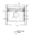
- a particularly expedient embodiment of the piston according to the invention is shown, the piston being shown in side view of a piston pin bore 2 in a cylinder 1 shown in section.
- this piston has three ring grooves arranged one above the other, the upper two of which each hold a compression ring and the bottom one of which has an oil scraper ring 4.
- the outer edge of the lowermost ring groove facing the piston skirt 5 is chamfered to form a chamfer 6.
- This chamfer is larger on the counter-pressure side 7 of the piston than on the Pressure side 8 of the piston.
- the width of the chamfer decreases continuously from the counter-pressure side to the pressure side, with its surface extending at an angle of approximately 10 ° to 30 ° to the piston axis 9.
- the chamfer width can also be narrowed step-wise towards the pressure side at a point between the counter pressure side and pressure side.
- the pressure side and counter pressure side depend on the direction of rotation of the crankshaft, which is shown in the drawing below with an arrow.
Abstract
Description
Die Erfindung betrifft einen Kolben für Brennkraftmaschinen mit einem in einer am Umfang seines Kopfteiles befindlichen Ringnut liegenden Ölabstreifring, wobei diejenige Außenkante der Ringnut, die dem an den Kopfteil des Kolbens anschließenden Kolbenschaft benachbart ist, unter Bildung einer Fase zum Kolbenschaft hin abgeschrägt ist.The invention relates to a piston for internal combustion engines with an oil scraper ring located in an annular groove on the circumference of its head part, the outer edge of the annular groove which is adjacent to the piston shaft adjoining the head part of the piston being chamfered toward the piston shaft to form a chamfer.
Bei Kolben, insbesondere Kolben für Brennkraftmaschinen, besteht das Problem, daß ein Schmiermittelmangel auf den Kolbenlaufflächen zu Trockenlauf führt, wodurch es auf diesen Laufflächen zu Freßerscheinungen kommen kann. Besonders die Gegendruckseite des Kolbens ist hiervon gefährdet, da beim Arbeits- und/oder Ansaugtakt des Kolbens, bei welchem dieser an seiner Druckseite anliegt, die Kolbenringe auf seiner Gegendruckseite radial über die Kolbenkontur vorstehend federnd gegen die Zylinderwand der Brennkraftmaschine abdichten und dabei den Ölfilm auf der Gegendruckseite weitgehend abstreifen. Beim anschließenden Verdichtungs- und/oder Ausschubtakt wird der Kolben dann gegen die schwach beölte Zylinderwandfläche der Gegendruckseite gedrückt, wobei der weitgehend abgestreifte Ölfilm durchschlagen werden kann, so daß es zu den genannten Freßerscheinungen kommt. Die Druckseite des Kölbens wird hingegen besser mit Öl versorgt, weil wegen der Ölbewegung in der Brennkraftmaschine infolge der Drehung der Kurbelwelle Öl bevorzugt auf die der Kolbendruckseite gegenüberliegende Zylinderwand geschleudert wird und der Kolbenschaft beim Abwärtshub immer in eine gut mit Öl benetzte Zylinderlauffläche hineingleitet. Dagegen liegt der Kolben im Aufwärtshub mit seiner Gegendruckseite an der vom Öl durch die Abstreifwirkung der Kolbenringe befreiten Zylinderwand an.With pistons, in particular pistons for internal combustion engines, there is the problem that a lack of lubricant on the piston running surfaces leads to dry running, which can lead to seizures on these running surfaces. In particular, the back pressure side of the piston is at risk from this, since during the working and / or intake stroke of the piston, in which the piston rests on its pressure side, the piston rings on its back pressure side project resiliently radially above the piston contour against the cylinder wall of the internal combustion engine and thereby open the oil film wipe off the counter pressure side to a large extent. During the subsequent compression and / or ejection stroke, the piston then pressed against the lightly oiled cylinder wall surface of the counter pressure side, whereby the largely stripped oil film can be penetrated, so that the above-mentioned seizure phenomena occur. The pressure side of the piston, on the other hand, is better supplied with oil, because due to the oil movement in the internal combustion engine due to the rotation of the crankshaft, oil is preferably thrown onto the cylinder wall opposite the piston pressure side and the piston shaft always slides into a cylinder surface well wetted with oil during the downward stroke. On the other hand, the piston in the upward stroke lies with its counter-pressure side on the cylinder wall freed from oil by the wiping action of the piston rings.
Um einen ausreichenden Ölfilm an den Laufflächen des Kolbens bzw. der gegenüberliegenden Zylinderwand zu erzeugen, hat man bisher folgende Maßnahmen vorgesehen:
- a) Man hat die Kolbenschaftrauhigkeit erhöht und damit den Traganteil des Kolbenschaftes verringert. Dies hat jedoch den Nachteil, daß am Kolbenhemd durch rasches Abschleifen der Drehpaßspitzen ein hoher Verschleiß eintritt.
- b) Man hat die Abstreifwirkung der Ölabstreifringe verringert. Dies führt jedoch zu einem hohen Ölverbrauch und damit zu einer hohen Verbrennung von Öl in der Brennkraftmaschine mit der Folge der Bildung von Ölkohle im Zylinder.
- (c) Man hat an den Kanten der den Ölabstreifring aufnehmenden Ringnut breite Fasen angeordnet, um dadurch zwischen dieser Fase und der gegenüberliegenden Zylinderwand einen Raum für ein ausreichendes Ölreservoir zu erhalten. Hierdurch wird jedoch der Traganteil des Kolbenschaftes verkleinert, wodurch sich dessen Flächenpressung erhöht. Dies kann auf der Druckseite des Kolbens zum Durchschlagen des Ölfilms und damit zum Trockenlauf des Kolbens führen.
- a) The roughness of the piston skirt has been increased, thus reducing the load on the piston skirt. However, this has the disadvantage that high wear occurs on the piston skirt due to the rapid grinding of the rotary fitting tips.
- b) The scraper effect of the oil scraper rings has been reduced. However, this leads to high oil consumption and thus to a high combustion of oil in the internal combustion engine, with the result that oil carbon is formed in the cylinder.
- (c) Wide chamfers have been arranged on the edges of the annular groove receiving the oil scraper ring, in order thereby to provide a space for a sufficient oil reservoir between this chamfer and the opposite cylinder wall. As a result, however, the bearing portion of the piston skirt is reduced, which increases its surface pressure. This can lead to the oil film breaking through on the pressure side of the piston and thus causing the piston to run dry.
Der Erfindung liegt daher die Aufgabe zugrunde, einen Kolben der eingangs genannten Gattung derart auszubilden, daß die vorgenannten Nachteile nicht gegeben sind, d.h. daß die Aufrechterhaltung eines zur Verhinderung des Trockenlaufes ausreichenden Ölfilms gesichert ist. Dies wird erfindungsgemäß dadurch erreicht, daß bei diesem Kolben die Breite der Fase an der dem Kolbenschaft benachbarten Außenkante der den Ölabstreifring aufnehmenden Ringnut an der Gegendruckseite des Kolbens größer ist als an der Druckseite des Kolbens. Hierdurch entsteht an der Gegendruckseite des Kolbens ein größerer Raum zwischen dieser Fase und der gegenüberliegenden Zylinderwand als auf der Druckseite des Kolbens, so daß sich an der Gegendruckseite ein größeres Ölreservoir bildet als an der Druckseite. Dieses größere Ölreservoir kann durch entsprechende Wahl der Fasenbreite, abhängig vom Hub und vom Durchmesser des Kolbens, so gewählt werden, daß es für eine ausreichende Beölung der Lauffläche des Kolbens bzw. der gegenüberliegenden Zylinderwand über den gesamten Kolbenhub ausreicht. Auf diese Weise kann ein Ölstau ebenso verhindert werden wie eine Unterversorgung mit Öl. Die geringere Breite der Fase an der Druckseite des Kolbens bewirkt, daß ein Abfließen des Öls von der Gegendruckseite verhindert wird, wodurch ein Durchschlagen des Ölfilmes an der Zylinderwand durch den Kolben auf seiner Gegendruckseite vermieden wird. Besonders im kalten Zustand der Brennkraftmaschine macht sich hierdurch eine Geräuschdämpfung bemerkbar.The invention is therefore based on the object of designing a piston of the type mentioned at the outset in such a way that the abovementioned disadvantages do not exist, ie that the maintenance of an oil film which is sufficient to prevent dry running is ensured. This is achieved according to the invention in that in this piston the width of the chamfer is greater on the outer edge of the annular groove receiving the oil scraper ring on the counterpressure side of the piston than on the pressure side of the piston. This creates a larger space on the back pressure side of the piston between this chamfer and the opposite cylinder wall than on the pressure side of the piston, so that a larger oil reservoir is formed on the back pressure side than on the pressure side. This larger oil reservoir can be chosen by appropriate selection of the chamfer width, depending on the stroke and the diameter of the piston, so that it is sufficient for sufficient oiling of the running surface of the piston or the opposite cylinder wall over the entire piston stroke. In this way, an oil spill can be prevented as well as an undersupply with Oil. The smaller width of the chamfer on the pressure side of the piston has the effect that the oil is prevented from flowing away from the counterpressure side, as a result of which the oil film on the cylinder wall does not penetrate through the piston on its counterpressure side. A noise reduction is particularly noticeable when the internal combustion engine is cold.
Dadurch, daß die breite Fase nicht wie beim bekannten Stand der Technik über den gesamten Kolbenumfang, sondern nur oder hauptsächlich nur im Bereich der Gegendruckseite des Kolbens angeordnet ist, wo wegen schlechter Ölversorgung ein größeres Ölreservoir benötigt wird, ist bei dem erfindungsgemäßen Kolben an seiner kritischen Seite ein ausreichender Ölfilm sichergestellt, ohne daß der druckseitige Tragbereich des Kolbens nennenswert verkleinert wird mit der Folge einer erhöhten Flächenpressung und der Gefahr, daß der Ölfilm dort durchschlagen wird.The fact that the wide chamfer is not arranged over the entire circumference of the piston, as in the known prior art, but only or mainly only in the region of the counterpressure side of the piston, where a larger oil reservoir is required because of poor oil supply, is critical in the piston according to the invention Sufficient oil film is ensured on the side without the pressure-bearing area of the piston being significantly reduced, with the result of increased surface pressure and the risk that the oil film will penetrate there.
Zweckmäßige Weiterbildungen des erfindungsgemäßen Kolbens ergeben sich aus den Unteransprüchen.Appropriate developments of the piston according to the invention result from the subclaims.
In der Zeichnung ist ein besonders zweckmäßiges Ausführungsbeispiel des erfindungsgemäßen Kolbens dargestellt, wobei der Kolben in einem im Schnitt gezeichneten Zylinder 1 in Seitenansicht auf eine Kolbenbolzenbohrung 2 dargestellt ist. In seinem Kopfteil 3 besitzt dieser Kolben drei übereinander angeordnete Ringnuten, deren beide oberen je einen Verdichtungsring und deren unterste einen Ölabstreifring 4 aufnehmen. Die dem Kolbenschaft 5 zugewandte Außenkante der untersten Ringnut ist unter Bildung einer Fase 6 abgeschrägt. Diese Fase ist auf der Gegendruckseite 7 des Kolbens größer als auf der Druckseite 8 des Kolbens. Die Breite der Fase nimmt von der Gegendruckseite zur Druckseite hin kontinuierlich ab, wobei sich ihre Fläche in einem Winkel von etwa 10° bis 30° zur Kolbenachse 9 erstreckt. Die Fasenbreite kann auch an einer Stelle zwischen Gegendruckseite und Druckseite stufenförmig zur Druckseite hin verengt sein.In the drawing, a particularly expedient embodiment of the piston according to the invention is shown, the piston being shown in side view of a
Die Druckseite und Gegendruckseite sind abhängig von der Drehrichtung der Kurbelwelle, die in der Zeichnung unten mit Pfeil dargestellt ist.The pressure side and counter pressure side depend on the direction of rotation of the crankshaft, which is shown in the drawing below with an arrow.
Claims (7)
dadurch gekennzeichnet, daß die Breite der sich über den gesamten Kolbenumfang erstreckenden Fase (6) an der Gegendruckseite (7) des Kolbens größer ist als an der Druckseite (8) des Kolbens.1. Piston for internal combustion engines with an oil scraper ring lying on the circumference of its head part in an annular groove, the outer edge of the annular groove adjacent to the piston shaft adjoining the head part being chamfered to form a chamfer,
characterized in that the width of the chamfer (6) extending over the entire circumference of the piston is greater on the counter-pressure side (7) of the piston than on the pressure side (8) of the piston.
Priority Applications (1)
| Application Number | Priority Date | Filing Date | Title |
|---|---|---|---|
| AT88102287T ATE67285T1 (en) | 1987-03-04 | 1988-02-17 | PISTONS FOR COMBUSTION ENGINES. |
Applications Claiming Priority (2)
| Application Number | Priority Date | Filing Date | Title |
|---|---|---|---|
| DE3706940 | 1987-03-04 | ||
| DE3706940A DE3706940C1 (en) | 1987-03-04 | 1987-03-04 | Pistons for internal combustion engines |
Publications (3)
| Publication Number | Publication Date |
|---|---|
| EP0280960A2 true EP0280960A2 (en) | 1988-09-07 |
| EP0280960A3 EP0280960A3 (en) | 1989-06-14 |
| EP0280960B1 EP0280960B1 (en) | 1991-09-11 |
Family
ID=6322253
Family Applications (1)
| Application Number | Title | Priority Date | Filing Date |
|---|---|---|---|
| EP88102287A Expired - Lifetime EP0280960B1 (en) | 1987-03-04 | 1988-02-17 | Pistons for internal-combustion engines |
Country Status (6)
| Country | Link |
|---|---|
| US (1) | US4787295A (en) |
| EP (1) | EP0280960B1 (en) |
| JP (1) | JPS63235646A (en) |
| AT (1) | ATE67285T1 (en) |
| BR (1) | BR8800928A (en) |
| DE (2) | DE3706940C1 (en) |
Families Citing this family (6)
| Publication number | Priority date | Publication date | Assignee | Title |
|---|---|---|---|---|
| US5029562A (en) * | 1989-12-05 | 1991-07-09 | Adiabatics, Inc. | Hybrid piston for high temperature engine |
| JP3789691B2 (en) * | 1999-09-14 | 2006-06-28 | 三洋電機株式会社 | High pressure compressor compressor |
| DE102005041908A1 (en) * | 2005-09-03 | 2007-03-08 | Ks Kolbenschmidt Gmbh | Piston with a arranged below an annular groove circumferential radial recess |
| US7614339B2 (en) * | 2006-12-21 | 2009-11-10 | Gm Global Technology Operations, Inc. | Piston top chamfer design to reduce noise and friction |
| DE102017218975A1 (en) | 2017-10-24 | 2019-04-25 | Federal-Mogul Nürnberg GmbH | Piston for an internal combustion engine |
| DE102019216252A1 (en) * | 2019-10-22 | 2021-04-22 | Mahle International Gmbh | Pistons for an internal combustion engine |
Citations (3)
| Publication number | Priority date | Publication date | Assignee | Title |
|---|---|---|---|---|
| US1664507A (en) * | 1922-02-09 | 1928-04-03 | Charles C Hanch | Lubricating piston |
| DE550963C (en) * | 1932-05-23 | Stihl Andreas | Pistons for two-stroke internal combustion engines | |
| US1864384A (en) * | 1931-10-13 | 1932-06-21 | Ware Raymond | Piston |
Family Cites Families (3)
| Publication number | Priority date | Publication date | Assignee | Title |
|---|---|---|---|---|
| US2407440A (en) * | 1944-01-07 | 1946-09-10 | Osborne Walter | Piston for internal-combustion engines |
| DE7526314U (en) * | 1975-08-20 | 1977-02-10 | Mahle Gmbh, 7000 Stuttgart | EGOSSEN ALUMINUM PLUNGER WITH PRESSED BOLT HUB AREAS |
| DE3338474A1 (en) * | 1983-10-22 | 1985-05-09 | Mahle Gmbh, 7000 Stuttgart | SUBMERSIBLE PISTON FOR COMBUSTION ENGINES |
-
1987
- 1987-03-04 DE DE3706940A patent/DE3706940C1/en not_active Expired
-
1988
- 1988-02-17 EP EP88102287A patent/EP0280960B1/en not_active Expired - Lifetime
- 1988-02-17 DE DE8888102287T patent/DE3864699D1/en not_active Expired - Lifetime
- 1988-02-17 AT AT88102287T patent/ATE67285T1/en not_active IP Right Cessation
- 1988-02-24 US US07/159,660 patent/US4787295A/en not_active Expired - Fee Related
- 1988-03-03 BR BR8800928A patent/BR8800928A/en not_active IP Right Cessation
- 1988-03-04 JP JP63051453A patent/JPS63235646A/en active Pending
Patent Citations (3)
| Publication number | Priority date | Publication date | Assignee | Title |
|---|---|---|---|---|
| DE550963C (en) * | 1932-05-23 | Stihl Andreas | Pistons for two-stroke internal combustion engines | |
| US1664507A (en) * | 1922-02-09 | 1928-04-03 | Charles C Hanch | Lubricating piston |
| US1864384A (en) * | 1931-10-13 | 1932-06-21 | Ware Raymond | Piston |
Also Published As
| Publication number | Publication date |
|---|---|
| ATE67285T1 (en) | 1991-09-15 |
| US4787295A (en) | 1988-11-29 |
| EP0280960B1 (en) | 1991-09-11 |
| DE3864699D1 (en) | 1991-10-17 |
| JPS63235646A (en) | 1988-09-30 |
| DE3706940C1 (en) | 1988-04-21 |
| BR8800928A (en) | 1988-10-11 |
| EP0280960A3 (en) | 1989-06-14 |
Similar Documents
| Publication | Publication Date | Title |
|---|---|---|
| EP1954966B1 (en) | Piston comprising a circumferential radial recess located below an annular groove | |
| DE19651112C5 (en) | Sealing device for a motor piston rod | |
| DE3534536C2 (en) | ||
| WO1995002753A1 (en) | Process and arrangement for supplying lubricant to a reciprocating piston engine | |
| DE19709170C2 (en) | Sealing for reciprocating machine parts, especially valve stem seals | |
| DE4007992C2 (en) | ||
| DE102012000241B4 (en) | Piston ring for 2-stroke engines | |
| DE2446870B2 (en) | PISTON ENGINE | |
| DE102008050277B4 (en) | Piston skirt oil retention for an internal combustion engine | |
| EP0280960B1 (en) | Pistons for internal-combustion engines | |
| DE19605588C2 (en) | Process for machining a cylinder liner in internal combustion engines | |
| DE3707462C2 (en) | ||
| DE3814769A1 (en) | PISTON RING ARRANGEMENT | |
| DE907007C (en) | Piston or cylinder seal | |
| DE3441919C2 (en) | ||
| DE3231336C2 (en) | Piston ring for a piston internal combustion engine with a cylinder running surface with lubricating openings | |
| EP1045175B1 (en) | Packing ring | |
| DE1526598A1 (en) | Device for reducing cylinder liner wear in plunger engines, especially for heavy duty operation | |
| DE676147C (en) | Pump for pumping liquid fuels | |
| DE19616474A1 (en) | Piston for stroke machine, such as internal combustion engine | |
| DE2805492A1 (en) | Cooling system for axial piston unit - has annular groove in cylinder wall portion at all times covered by moving piston | |
| DE202007017339U1 (en) | piston engine | |
| WO1999031360A1 (en) | Two stroke spark ignition engine with separate lubrication | |
| DE2541579A1 (en) | SUBMERGED PISTON FOR COMBUSTION ENGINES WITH PISTON SHIRT THICKENED IN THE LOWER STEM AREA | |
| DE19952097B4 (en) | Internal combustion engine |
Legal Events
| Date | Code | Title | Description |
|---|---|---|---|
| PUAI | Public reference made under article 153(3) epc to a published international application that has entered the european phase |
Free format text: ORIGINAL CODE: 0009012 |
|
| AK | Designated contracting states |
Kind code of ref document: A2 Designated state(s): AT DE ES FR GB IT NL SE |
|
| RIN1 | Information on inventor provided before grant (corrected) |
Inventor name: BOEHM, GERHARD Inventor name: MARTIN, EDGAR Inventor name: OBERMEIER-WAGNER, KARL HEINZ |
|
| PUAL | Search report despatched |
Free format text: ORIGINAL CODE: 0009013 |
|
| RHK1 | Main classification (correction) |
Ipc: F16J 1/08 |
|
| AK | Designated contracting states |
Kind code of ref document: A3 Designated state(s): AT DE ES FR GB IT NL SE |
|
| 17P | Request for examination filed |
Effective date: 19890612 |
|
| 17Q | First examination report despatched |
Effective date: 19900725 |
|
| GRAA | (expected) grant |
Free format text: ORIGINAL CODE: 0009210 |
|
| AK | Designated contracting states |
Kind code of ref document: B1 Designated state(s): AT DE ES FR GB IT NL SE |
|
| PG25 | Lapsed in a contracting state [announced via postgrant information from national office to epo] |
Ref country code: SE Effective date: 19910911 Ref country code: NL Effective date: 19910911 Ref country code: ES Free format text: THE PATENT HAS BEEN ANNULLED BY A DECISION OF A NATIONAL AUTHORITY Effective date: 19910911 |
|
| REF | Corresponds to: |
Ref document number: 67285 Country of ref document: AT Date of ref document: 19910915 Kind code of ref document: T |
|
| ITF | It: translation for a ep patent filed |
Owner name: BARZANO' E ZANARDO MILANO S.P.A. |
|
| REF | Corresponds to: |
Ref document number: 3864699 Country of ref document: DE Date of ref document: 19911017 |
|
| GBT | Gb: translation of ep patent filed (gb section 77(6)(a)/1977) | ||
| ET | Fr: translation filed | ||
| PGFP | Annual fee paid to national office [announced via postgrant information from national office to epo] |
Ref country code: GB Payment date: 19920211 Year of fee payment: 5 |
|
| NLV1 | Nl: lapsed or annulled due to failure to fulfill the requirements of art. 29p and 29m of the patents act | ||
| PGFP | Annual fee paid to national office [announced via postgrant information from national office to epo] |
Ref country code: AT Payment date: 19920228 Year of fee payment: 5 |
|
| PLBE | No opposition filed within time limit |
Free format text: ORIGINAL CODE: 0009261 |
|
| STAA | Information on the status of an ep patent application or granted ep patent |
Free format text: STATUS: NO OPPOSITION FILED WITHIN TIME LIMIT |
|
| 26N | No opposition filed | ||
| PG25 | Lapsed in a contracting state [announced via postgrant information from national office to epo] |
Ref country code: GB Effective date: 19930217 Ref country code: AT Effective date: 19930217 |
|
| GBPC | Gb: european patent ceased through non-payment of renewal fee |
Effective date: 19930217 |
|
| REG | Reference to a national code |
Ref country code: FR Ref legal event code: TP |
|
| PG25 | Lapsed in a contracting state [announced via postgrant information from national office to epo] |
Ref country code: IT Free format text: LAPSE BECAUSE OF NON-PAYMENT OF DUE FEES;WARNING: LAPSES OF ITALIAN PATENTS WITH EFFECTIVE DATE BEFORE 2007 MAY HAVE OCCURRED AT ANY TIME BEFORE 2007. THE CORRECT EFFECTIVE DATE MAY BE DIFFERENT FROM THE ONE RECORDED. Effective date: 20050217 |
|
| PGFP | Annual fee paid to national office [announced via postgrant information from national office to epo] |
Ref country code: FR Payment date: 20060202 Year of fee payment: 19 |
|
| PGFP | Annual fee paid to national office [announced via postgrant information from national office to epo] |
Ref country code: DE Payment date: 20060228 Year of fee payment: 19 |
|
| REG | Reference to a national code |
Ref country code: FR Ref legal event code: ST Effective date: 20071030 |
|
| PG25 | Lapsed in a contracting state [announced via postgrant information from national office to epo] |
Ref country code: DE Free format text: LAPSE BECAUSE OF NON-PAYMENT OF DUE FEES Effective date: 20070901 |
|
| PG25 | Lapsed in a contracting state [announced via postgrant information from national office to epo] |
Ref country code: FR Free format text: LAPSE BECAUSE OF NON-PAYMENT OF DUE FEES Effective date: 20070228 |