EP0280941B1 - Vehicle wheel alignment apparatus and method - Google Patents
Vehicle wheel alignment apparatus and method Download PDFInfo
- Publication number
- EP0280941B1 EP0280941B1 EP88102006A EP88102006A EP0280941B1 EP 0280941 B1 EP0280941 B1 EP 0280941B1 EP 88102006 A EP88102006 A EP 88102006A EP 88102006 A EP88102006 A EP 88102006A EP 0280941 B1 EP0280941 B1 EP 0280941B1
- Authority
- EP
- European Patent Office
- Prior art keywords
- wheel
- light
- tire
- electrical signals
- points
- Prior art date
- Legal status (The legal status is an assumption and is not a legal conclusion. Google has not performed a legal analysis and makes no representation as to the accuracy of the status listed.)
- Expired - Lifetime
Links
Images


Classifications
-
- G—PHYSICS
- G01—MEASURING; TESTING
- G01B—MEASURING LENGTH, THICKNESS OR SIMILAR LINEAR DIMENSIONS; MEASURING ANGLES; MEASURING AREAS; MEASURING IRREGULARITIES OF SURFACES OR CONTOURS
- G01B11/00—Measuring arrangements characterised by the use of optical techniques
- G01B11/26—Measuring arrangements characterised by the use of optical techniques for measuring angles or tapers; for testing the alignment of axes
- G01B11/275—Measuring arrangements characterised by the use of optical techniques for measuring angles or tapers; for testing the alignment of axes for testing wheel alignment
- G01B11/2755—Measuring arrangements characterised by the use of optical techniques for measuring angles or tapers; for testing the alignment of axes for testing wheel alignment using photoelectric detection means
-
- G—PHYSICS
- G01—MEASURING; TESTING
- G01B—MEASURING LENGTH, THICKNESS OR SIMILAR LINEAR DIMENSIONS; MEASURING ANGLES; MEASURING AREAS; MEASURING IRREGULARITIES OF SURFACES OR CONTOURS
- G01B2210/00—Aspects not specifically covered by any group under G01B, e.g. of wheel alignment, caliper-like sensors
- G01B2210/10—Wheel alignment
- G01B2210/14—One or more cameras or other optical devices capable of acquiring a two-dimensional image
- G01B2210/143—One or more cameras on each side of a vehicle in the main embodiment
-
- G—PHYSICS
- G01—MEASURING; TESTING
- G01B—MEASURING LENGTH, THICKNESS OR SIMILAR LINEAR DIMENSIONS; MEASURING ANGLES; MEASURING AREAS; MEASURING IRREGULARITIES OF SURFACES OR CONTOURS
- G01B2210/00—Aspects not specifically covered by any group under G01B, e.g. of wheel alignment, caliper-like sensors
- G01B2210/10—Wheel alignment
- G01B2210/14—One or more cameras or other optical devices capable of acquiring a two-dimensional image
- G01B2210/146—Two or more cameras imaging the same area
-
- G—PHYSICS
- G01—MEASURING; TESTING
- G01B—MEASURING LENGTH, THICKNESS OR SIMILAR LINEAR DIMENSIONS; MEASURING ANGLES; MEASURING AREAS; MEASURING IRREGULARITIES OF SURFACES OR CONTOURS
- G01B2210/00—Aspects not specifically covered by any group under G01B, e.g. of wheel alignment, caliper-like sensors
- G01B2210/10—Wheel alignment
- G01B2210/22—Wheels in a state of motion supported on rollers, rotating platform or other structure substantially capable of only one degree of rotational freedom
-
- G—PHYSICS
- G01—MEASURING; TESTING
- G01B—MEASURING LENGTH, THICKNESS OR SIMILAR LINEAR DIMENSIONS; MEASURING ANGLES; MEASURING AREAS; MEASURING IRREGULARITIES OF SURFACES OR CONTOURS
- G01B2210/00—Aspects not specifically covered by any group under G01B, e.g. of wheel alignment, caliper-like sensors
- G01B2210/10—Wheel alignment
- G01B2210/26—Algorithms, instructions, databases, computerized methods and graphical user interfaces employed by a user in conjunction with the wheel aligner
-
- G—PHYSICS
- G01—MEASURING; TESTING
- G01B—MEASURING LENGTH, THICKNESS OR SIMILAR LINEAR DIMENSIONS; MEASURING ANGLES; MEASURING AREAS; MEASURING IRREGULARITIES OF SURFACES OR CONTOURS
- G01B2210/00—Aspects not specifically covered by any group under G01B, e.g. of wheel alignment, caliper-like sensors
- G01B2210/10—Wheel alignment
- G01B2210/28—Beam projector and related sensors, camera, inclinometer or other active sensing or projecting device
- G01B2210/283—Beam projectors and related sensors
- G01B2210/286—Projecting a light pattern on the wheel or vehicle body
-
- Y—GENERAL TAGGING OF NEW TECHNOLOGICAL DEVELOPMENTS; GENERAL TAGGING OF CROSS-SECTIONAL TECHNOLOGIES SPANNING OVER SEVERAL SECTIONS OF THE IPC; TECHNICAL SUBJECTS COVERED BY FORMER USPC CROSS-REFERENCE ART COLLECTIONS [XRACs] AND DIGESTS
- Y10—TECHNICAL SUBJECTS COVERED BY FORMER USPC
- Y10T—TECHNICAL SUBJECTS COVERED BY FORMER US CLASSIFICATION
- Y10T29/00—Metal working
- Y10T29/53—Means to assemble or disassemble
- Y10T29/53909—Means comprising hand manipulatable tool
- Y10T29/53913—Aligner or center
- Y10T29/53922—Auto wheel with auto chassis
Landscapes
- Physics & Mathematics (AREA)
- General Physics & Mathematics (AREA)
- Length Measuring Devices By Optical Means (AREA)
Description
- The present invention relates to a non-contact system for measuring a predetermined alignment characteristic of a wheel of a vehicle according to the preamble of
claim 1. - The invention further relates to a method of measuring a predetermined alignment characteristic of a wheel of a vehicle according to the preamble of
claim 12. - A system and a method of the aforementioned kind are known from document DE-A-27 27 420.
- The automotive industry, in recent years, has become increasingly interested in improving the quality of its vehicles, while at the same time seeking more efficient manufacturing procedures. One area of great potential for improvement is in verifying and adjusting wheel alignment settings.
- Present day wheel alignment and inspection is cumbersome and relies heavily on direct contact measuring devices to obtain a reading of whether the wheel is properly aligned. Aside from being cumbersome, conventional wheel alignment verification and adjusting techniques suffer a number of other shortcomings. These shortcomings are in part attributable to difficulty in obtaining an accurate measurement due to variations in tire and wheel size, variations in tire type, variations in vehicle weight and wheel base and variations in vehicle drive method and placement of the inspection stations. Other factors, perhaps equally important, are wear on the testing apparatus over time and distortion of the tire profile caused by the direct contact of measuring tools.
- If a high quality product is to be consistantly produced, such parameters as wheel alignment must be carefully monitored during the manufacturing process. Preferably, the accuracy of an alignment system should be equal or exceed the manufacturing specifications and should be easy to use on the assembly line. Present day alignment equipment is generally deficient in one or both of these regards.
- Even after the vehicle leaves the assembly line and is placed in service, there is a need for periodic inspection and adjustment of the wheel alignment settings. Proper wheel alignment can be lost if the vehicle is involved in a collision or even through normal service on bumpy roadways. Improper wheel alignment is a major contributing factor in tire wear and should therefore be periodically checked. Ideally, when a vehicle is brought in to a dealer or service station for wheel alignment, the alignment settings should be returned to the original factory specifications. Thus, the dealer or service station must also have accurate alignment equipment which is capable of meeting factory specifications.
- Document DE-A-27 27 420 discloses an apparatus for measuring the camber and toe-in of a motor vehicle. This prior art apparatus uses mirrors which are attached to the motor vehicle wheels on opposite sides of the vehicle. On both sides of the vehicle laser light sources are provided which emit a laser beam being directed on the surface of the mirrors at an accute angle. The reflected laser beams are then received by respective optical receivers, e.g. a video camera. The light beams generate light dots on the mirror surfaces on both latera sides of the vehicle so that narrow laser light beams are reflected onto the video cameras. The video cameras allow to determine the particular coordinate position of the light dot generated by reflected laser beam on an appropriate receiver surface within the video cameras. The video cameras are each connected to an indicating instrument which comprise a red light and a green light each in order to indicate whether or not the received light dot within the video camera was received within or out of a predetermined tolerance band.
- Consequently, this prior art apparatus has a number of disadvantages. For, this prior art apparatus requires attachment of mirrors to the wheels of the vehicle which is not at all as suitable for use on an assembly line because the step of attaching a mirror to the wheel is a time-consuming manual operation. Moreover, the accuracy of the resulting measurement is directly related to the position with which the mirror is attached to the wheel. For example, it can readily be appreciated that if the mirror is not precisely oriented relative to the plane of the wheel, the axis of the reflected light signal will be effected, thereby resulting in an inaccurate indication of the true state of wheel alignment. Thus, this prior art apparatus introduces another source of inaccuracy into the measurement.
- Further, the prior art apparatus is provided with tolerance indicating units, the purpose of which is to indicate whether or not the lasers are precisely oriented with respect to the vehicle, the wheels of which are to be measured with respect to their alignment. This is a clear indication that the prior art apparatus requires precise aiming of the lasers because otherwise the tolerance indicating units would not be needed. The prior art apparatus also requires precise control of the distance from the mirrors to the light receivers.
- Further, another substantial drawback of this prior art apparatus is that it does not measure the position and orientation of the plane of the wheel in three-dimensional space. For, the prior art apparatus is merely reflecting a light beam of a mirror, thereby creating a simple dot image, as mentioned above. The prior art apparatus looks for the reflected dot image to appear at a specific location indicative of the wheel being properly aligned. No measurement or determination of the location and orientation of the plane of the wheel is made. In fact, as noted, the dot provides insufficient information to even make such determination.
- Document DE-A-35 26 923 discloses a method and an apparatus for non-contact determination of surfaces. In particular, this prior art discloses an apparatus for measuring a surface of a railroad wheel running on a rail. For doing so, a laser beam is directed onto a surface of the wheel under an accute angle and the reflected beam of laser light is received in a camera. Both the laser light source and the camera are fixed in space. The measurement is performed while the wheel runs on the rail. Therefore, the light dot created by the laser light source on the wheel surface will travel on the wheel surface due to the relative movement between the wheel and the laser light source. Due to the irregular wheel surface, the light dot will not travel along a linear path but rather on a curved path. Therefore, the camera will receive a characteristic curve corresponding to the light dot path on the wheel surface. This characteristic curve may then be compared with standard reference curves, stored in a memory in order to make a statement about the wear of the wheel after long-time use.
- However, this prior art apparatus is not intended to be used for measuring camber or caster or toe-in of a vehicle wheel because, as is generally known, railroad car wheels are not inclined in any way with respect to the car body.
- Document DE-A-29 48 573 describes a method and an apparatus for non-contact measuring of motor vehicle axles. For doing so, television cameras are mounted on both lateral sides of the motor vehicle, the cameras being adapted to be pivoted about a vertical axis so that they may be alternately directed each onto the front wheel and, alternately, onto the rear wheel of the vehicle and on the specific vehicle side. As the television cameras are roughly situated in a position corresponding to have the distance between the front axle and the rear axle, the cameras will receive an elliptic picture of either the front wheel or the rear wheel. The prior art apparatus teaches to compare such elliptic images in order to make a determination on the orientation of the axles and the steering geometry thereof.
- Instead of using a video camera receiving the elliptic picture of a wheel illuminated continuously by a light source, a laser beam may be used for illumination of a wheel. If the laser beem is scanned in a series of lines instead of a video camera, a simple light detecting diode can be used for evaluation.
- However, this illumination with scanning laser light is merely used instead of a video camera detecting the image of a continuous light source. Again, the elliptic pictures are evaluated in order to make a determination on the orientation of the axles and the steering geometry thereof. Therefore, the precision of the measurements is directly coordinated to the precision of range measurement between the video camera or the laser light source and the respective wheel and, in particular, related to the form and outer shape of the wheel or of the rim respectively. Therefore, the precision of such a prior art method is not suited for monitoring wheel alignment parameters in a manufacturing process.
- Documemt DE-A-31 43 173 discloses a measuring apparatus for measuring the inclination of an object to be measured by means of a reflection methos. In particular, this prior art apparatus is intended to be used for measuring the camber and toe-in of a vehicle.
- Very much like the prior art apparatus of document DE-A 27 27 420, mentioned and commented above, this prior art apparatus uses mirrors which have to be attached to the vehicle wheels in order to perform the measurement. Moreover, this prior art apparatus uses two different lasers which are directed on the mirror to generate a light dot thereon. The arrangement is such that the reflected narrow laser beams coincide on one single light dot on a screen being interposed between a camera and the mirror. Therefore, this prior art method and apparatus incorporates the same disadvantages and drawbacks as the apparatus according to document DE-A-27 27 420.
- In contrast to this prior art, there is a need in a modern motor car manufacturing in automotive assembly plants to set the proper alignment of the wheels of a newly assembled vehicle as a vehicle advances along an assembly line.
- Therefore, it is an object of the invention to provide an apparatus and method for measuring wheel alignment characteristics on a vehicle, which are easy to be used, which guarantee precise measurements and which allow to directly readjust the wheel, if necessary, in order to put the wheel into predetermined alignment characteristics conditions.
- According to the invention, this object is achieved by a system comprising the features of
claim 1. - Moreover, according to the invention, the object is further achieved by a method using the features of
claim 12. - This invention is particularly adapted for use in an automotive assembly plant to set the proper alignment of the wheels of a newly assembled vehicle as the vehicle advances along an assembly line. In contrast to the pertinent prior art systems and measurement methods, the system and method according to this invention are fundamentally different from the approach taught by the prior art. In particular, the present system and method derive the measurement data by directing a geometrically structured light pattern directly on the wheel or tire of the vehicle. Nothing need be attached to the wheel. Moreover, the present system and method are capable of extremely accurate measurements despite the inherent imperfections and variables (such as lettering) which commonly appear on the sidewalls of most tires. Moreover, the present invention possesses no limitations with respect to precise aiming of the lasers. In fact, this geometrically structured light source - in the preferred embodiment a line projected transverse to the sidewall of the tire from the bead to the tread - need only impinge on the tire sidewall. No critical aiming of the laser is required. Furtherthemore, the present invention can readily accommodate wheels of different diameter which can frequently occur on an assembly line where the same vehicle may optionally be equipped with different tires and wheel sizes.
- In addition, the system and method according to this invention have the ability to measure the alignment of a wheel as long as it is positioned properly within the measurement zone of the sensor, which includes a predefined depth of field. Consequently, precise spacing of the wheel of the vehicle relative to the sensor is not required.
- Another fundamental difference between the present invention and the aforementioned prior art is that the present invention actually measures the position and orientation of the plane of the wheel in three-dimensional space other than the prior art apparatuses which only detect the point of impingement of a dot-shaped laser beam on a receiver plane within a camera. In contrast, according to the invention, a geometrically structured light pattern is optically created on the wheel or tire which contains sufficient information to define in three-dimensional space the plane of the wheel in order for the present invention to function.
- The present invention provides an apparatus and method for measuring and effecting wheel alignment, in which the position and angular orientation of the wheel is determined without physical contact. Measurements are performed by a self-contained, intelligent machine vision camera and an illumination system which includes a laser source for projecting a geometrically structured light pattern onto the wheel, tire, or other integral part of the wheel. A solid-state television camera precisely located within the camera illumination unit or sensor module, at a perspective angle relative to the axis of the projected light plane, produces image signals representing the light pattern or contour of the surface of the wheel or tire, as viewed from a perspective angle.
- Control circuitry within the sensor module (camera illumination unit) transmits the image signals in response to commands from an attached machine vision computer. The computer converts these signals into digital form and stores them as an organized array of digital values representing an analog image. The machine vision computer processes the image, using prestored calibration data or n-th order polynomial transformations and preprogrammed algorithms to compute the three-dimensional position of specific reference points on the imaged object. Multiple sensor modules, rapidly, sequenced by the machine vision computer, permit essentially simultaneous measurements to be made at two or more points on each wheel or tire. With these data points, the rotational plane of the wheel can be calculated. This wheel position information can be combined with similarly measured data defining the vehicle center line or other desired references and the complete vehicle alignment geometry can be analyzed and dynamically displayed on a meter or the like to guide an operator in adjusting or setting the wheel alignment. The system provides a fast response time to the operator making the adjustment while viewing the meter, through rapidly sequenced operation and hardware assisted data point location and other techniques discussed below. Alternatively, the results of the geometric alignment analysis can be transmitted digitally to an automatic mechanism for performing the same operations. The analysis can also be used for quality control testing on an assembly line by providing an indication of any misaligned wheels and also providing a printout of each wheel's actual alignment settings, if desired.
- In accordance with the invention method of aligning a vehicle wheel, structured light is projected in a plane onto the surface of a member integral with the wheel, such as the tire. This structured light illuminates at least two contour lines on different portions of the wheel. The contour lines are then optically read using an optical sensor disposed at a viewing angle offset from the plane of the structured light and data points are collected to indicate the position of the contour lines. At least one datum point associated with each of the contour lines is located corresponding to radially equivalent points (radially equidistant from the axis of rotation of the wheel) on the surface of the wheel. For example, an annular surface of the tire closest to the light projecting laser may be selected as the position from which the points are taken. Using the individual datum points so located, the position of the wheel is determined and an indication of the wheel position relative to a desired position is given to an operator. Thereafter the wheel position may be adjusted based on the indication, in order to bring the wheel into alignment with the desired position.
- For a more complete understanding of the invention and its many objects and advantages, reference may be had to the following specification and to the accompanying drawings.
-
- Figure 1 is a plan view of an exemplary wheel with integral tire and associated suspension system useful inexplaining toe-in alignment;
- Figure 2 is a rear view of the wheel, tire and associated suspension system of Figure 1 useful in explaining camber;
- Figure 3 is a perspective view of the invention shown in conjuction with the left front wheel and tire of an exemplary vehicle;
- Figure 4 is a top perspective view of the invention and exemplary vehicle, illustrating sensor placement;
- Figure 5 is a dragrammatic top view of the invention illustrating the left and right front sensors;
- Figure 6 is a diagrammatic front view of the invention illustrating the left and right front sensors;
- Figure 7 illustrates one of the sensors of the invention in greater detail;
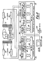
- Figure 8 is a block schematic diagram of the invention illustrating the control circuitry and machine vision computer and illustrating the system bus architecture;
- Figure 9 is a block schematic diagram of the sequencer cirucit of the invention;
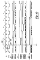
- Figure 10 is a timing diagram useful in explaining the frame sequencing operation of the sequencer circuit;
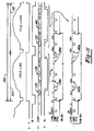
- Figure 11 is another timing diagram useful in explaining the video framing operation of the sequencer circuit;
- Figure 12 is a timing diagram useful in explaining the line bracketing operation of the sequencer circuit;
- Figure 13 is a timing diagram depicting the video/bus arbitration scheme of the sequencer circuit;
- Figure 14 is a timing diagram useful in explaining the outlatch circuit of the sequencer circuit;
- Figure 15 is a block diagram of the transition detector of the sequencer circuit;
- Figure 16 is a representation of the image data perceived by the optical sensor of the invention;
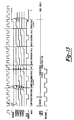
- Figure 17 is a graph of optical intensity as a function of distance from the laser light source for two exemplary scan lines of data depicted in Figure 16;
- Figure 18 is an enlarged graph of one of the two intensity patterns of Figure 17 with the distance scale along the abscissa being reversed relative to Figure 17;
- Figure 19 is a graph depicting a plurality of overlayed received intensity curves with center of gravity points indicated, useful in illustrating the algorithm by which data points are selected.
- Figure 20 is a graph of optical intensity similar to Figure 18 illustrating a preferred alogorithm for eliminating measurement error due to tire sidewall lettering;
- Figure 21 is a sketch illustrating how toe-in angle is determined trigonometrically from measured (y,z) data;
- Figures 22A and 22B illustrate a wheel at two different steered orientations for purposes of explaining caster angle;
- Figure 23 is a sketch depicting the intersection of the planes of the wheels of Figures 22A and 22B, useful in explaining caster angle;
- Figure 24 depicts an alternate method of determining toe-in, camber and caster.
- The present invention provides a noncontact sensor useful in measuring wheel alignment. In Figures 1 and 2 an exemplary left front wheel is illustrated generally at 10. In Figures 1 and 2 the
tire 12 is illustrated. The tire is integral withwheel 10 so that both may rotate about the same axis ofrotation A. Wheel 10 defines a medial plane C which is perpendicular to axis of rotation A. In addition to thetire 12, the wheel may also have other integral members, such as a wheel cover, hubcap or the like. Unless otherwise specified, the term "wheel" is used generically herein and in the accompanying claims to refer to the unsprung rotating mass of the vehicle, including but not limited to the metal wheel, brake rotor, tire, wheel cover, hubcap and the like. - Figures 1 and 2 further depict exemplary components of the front suspension system. Figures 1 and 2 thus depict the
suspension control arm 14,suspension spring 16, tie-rod 18,shock absorber 20 and ball joint 22. In Figure 1 the front most part of the vehicle is at the top of the page. In Figure 2 thetire 12 rests upon the ground line G. The spatial position of the wheel (and its integral components such as tire 12) may be defined in relation to the ground line G and a longitudinal line L which passes through two fixed points on the vehicle. For convenience, longitudinal line L is shown extending through the front andrear bolts - The position of
wheel 10 may be determined in relation to the longitudinal line L and the perpendicular line P. In Figure 1, a second longitudinal line L' is drawn parallel to longitudinal line L so that it passes through wheel axis W. The angle between longitudinal line L' and the center plane C establishes the toe-in of the wheel. A positive wheel toe-in is illustrated in Figure 1. Wheel positions which place the center plane C counterclockwise of longitudinal line L' in Figure 1 would yield a negative toe-in. Similarly, in Figure 2, the angle between the center plane C and the perpendicular line P establishes the wheel camber. A positive camber is illustrated in Figure 2. A negative camber would result if the center plane C is clockwise of perpendicular line P as seen in Figure 2. Referring to Figures 22A and 22B, when thewheel 10 is turned during steering, the plane passing through the wheel rotates in a plane which defines an angle with respect to the vertical known as the caster angle. Figures 22A and 22B illustratewheel 10 in two different steered orientations. The plane of the wheel in Figure 22A si designated at C₁ and the plane of the wheel in Figure 22B is illustrated at C₂. The intersection of planes C₁ and C₂ is illustrated in Figure 23 and defines a line designated K. This line defines an angle with respect to the vertical P which is known as the caster angle. The caster angle is determined by the orientation of the steering system kingpin about which the wheel is turned when steering the vehicle. - The toe-in, camber and caster measurements of the wheel are important in establishing proper wheel alignment. The present invention provides method and apparatus for measuring these and other wheel and vehicle suspension and steering parameters. The toe-in may be adjusted by means of the threaded joint of the connector on tie-
rod 18. - The present invention employs a noncontact sensor arrangement without moving parts for determining the spatial position of the wheel and its associated tire and other integral components. The invention employs a laser light source for projecting structured light which in the preferred embodiment is directed onto the sidewall of the tire. A video optical sensor disposed at a viewing angle offset from the plane of the structured light detects the illuminated contour line or lines on different portions of the tire and these contour lines are used to construct a computer memory image. The computer memory image is interpreted by alogrithms which give the wheel position and compare that position with a desired wheel position. The apparatus and method may be used while the wheel is rotating (i.e., dynamic wheel alignment), which has the advantage of averaging the wheel position measurement over time to give more consistent results. The invention may also be adapted for stationary wheel measurement techniques (i.e., static wheel alignment), if desired. Significantly, the present invention does not require the attachment of reflective devices to the wheel or tire. This adds to the accuracy of the invention, since unwanted variations in reflector attachment is of no concern.
- As it is the more difficult of the two alignment schemes to implement, the preferred embodiment of the present invention described herein represents a dynamic wheel alignment system. Modification to a static wheel alignment system, however, is readily achievable. Figure 3 illustrates an
exemplary vehicle 28 with left fromwheel 10 andtire 12 visible.Wheel 10 includes anintegral wheel cover 13 in Figure 3, although the invention may be practiced with the wheel cover removed.Tire 12 rests on aroller track 30 which allows the wheel to rotate about its axis. In a dynamic wheel alignment system, the roller track is motorized for rotating the wheel at a predetermined speed (e.g., equivalent to a vehicle speed of 30 miles per hour.) Alternative means of rotating the wheel may be provided. Positioned at a stationadjacent roller track 30 is anoncontact sensor station 32. The sensor station includes ahousing 34 which protects one ormore sensor modules 36 and associated electronic components yet to be discussed. Each sensor module, discussed more fully below, includes a laser light source and video camera sensor with associated imaging lenses and interface electronics. The sensor modules each project strucured light in at least one plane onto the sidewall of thetire 12. The term "structured light" means light which is projected in a predetermined geometric pattern and may include both coherent (laser) and noncoherent light. In the presently preferred embodiment, the structured light comprises a flat plane formed by optically fanning a laser beam. Other structured light configurations are also usable. - The structured light projected onto the sidewall of
tire 12 shows up as illuminatedcontour lines 38. Three such contour lines are shown in Figure 3. These may be projected using three sensor modules withinhousing 34. Each of the illuminated contour lines is viewed by a video camera within the associated sensor module. The video cameras produce video images of the contour lines as seen from the offset vantage point or offset viewing angle of the video camera sensors relative to the laser light sources. For illustration purposes, avideo monitor 40 is depicted in Figure 3. On the screen ofmonitor 40 appears a contour line image 42 which is exemplary of the type of image received by the video camera of one of thesensor modules 36. This contour line image is processed by digital computer circuitry of the invention to determine the position of the wheel. This processing is accomplished largely without human intervention and themonitor 40 is not required.Monitor 40 and the contour line image displayed on it are illustrated in Figure 3 to aid in understanding the invention. - In some applications, it is considered desirable to be able to monitor all four wheels of a vehicle at one wheel alignment station. Sucn an arrangement is illustrated in Figure 4, which illustrates left front and left rear
noncontact sensor stations 32 positioned adjacent the associated roller tracks 30. Avehicle 28 is shown in position on the roller tracks. - Figures 5 and 6 diagrammatically illustrate an exemplary alignment station using the invention. For illustration purposes only the
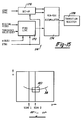
tires 12 of the vehicle are shown in Figures 5 and 6. The exemplary alignment station is constructed over apit 44 for allowing workers to access the underside of the vehicle or for placement of robotic equipment.Noncontact sensor stations 32 are positioned on both left and right sides of the vehicle, as illustrated. - Figure 5 shows the fanned
laser beams 46 which project generally horizontal contour lines upon the associated tires in both fore and aft positions. In contrast with the illustration of Figure 3 (which shows three projected contour lines), Figures 5 and 6 depict the projection of only two structured light planes onto each tire. Both light patterns are in a generally horizontal plane. This arrangement is appropriate for measuring the toe-in angle. The generally vertically arranged plane of structured light shown in Figure 3 is used to check camber and is not shown in Figures 5 and 6. - Referring to Figure 5, each
laser beam plane 46 subtends an arc "a" which is sufficient to project a contour line across a portion of the tire surface. Figure 6 depicts theplane 46 of each laser beam in relation to theviewing angle 48 of the video optical sensor located in the associated sensor module of eachsensor station 32. As seen from Figure 6, theviewing angle 48 is offset from thelaser plane 46. This offset allows the use of triangulation in determining the position of the wheel from its reflected contour lines. These triangulation calculations are performed by the associated digital computer and can provide a readout to the worker for use in adjusting the toe-in alignment, for example. Readouts in the form ofanalog meters 50 are illustrated in Figure 5. Digital readouts may also be employed. In addition, the data produced by the invention can be recorded and compared with predefined tolerances for quality control and record maintenance purposes and may also be used to control robotic equipment. - A
sensor module 36 is illustrated in detail in Figure 7. The components of the sensor module are housed in a metal cabinet orbox 52 which has a finned exterior surface for heat dissipation.Cabinet 52 has a lid which has been removed in Figure 7 to show the internal components. Alaser diode assembly 54 is positioned adjacent alaser window 56 which is covered with aglass plate 58. On the same wall ofcabinet 52 is an imaging window 60 which is covered byglass plate 62. The laser diode assembly produces an optically fanned light plane using optics of the type described in Patent No. 4,645,348. Positioned withincabinet 52 adjacent the imaging window is abase leg mirror 64. The mirror is positioned so that light entering through the imaging window enters an anamorphic lens 66. The anamorphic lens has a first focal length along one axis and a different focal length along a second orthogonal axis. The anamorphic lens thus produces expanded resolution in one plane and compressed resolution in another plane. This gives one magnification along the axis orthogonal to the length of the contour line and different magnifcation along the axis parallel to the length of the contour line. By positioning the anamorphic lens properly, the plane of greater focal length and thus higher magnification is aligned generally perpendicular to the length of the imaged contour line. Positioned behind the anamorphic lens is an imaging lens 68 which projects through aninterference filter 70 into thevideo camera assembly 72. Also housed withincabinat 52 are theinterface electronics 74 which couple between the video camera assembly and the digital computer equipment yet to be discussed. The above-described optical arrangement provides a suitable field in both the y and z directions, while maintaining sufficient resolution to componsate for the wide variation in vehicle track, wheel size and tire section. - Referring now to Figure 8, a general computer system overview will be given. In Figure 8 four
sensor modules 36 are illustrated, two for the right front wheel and two for the left front wheel. It will be understood that the same arrangement could be provided for the left and right rear wheels if desired. Also illustrated are twoanalog meters 50 which the worker may use to set the toe-in alignment. The presently preferred computer system is built around a Motorola VME bus architecture, although other buses, such as the Multibus II, may also be used. The computer system interface comprises analignment processor engine 76 and an integrated host/alignment processor engine 78.Processor engines separate VME buses VME bus 80 is anMVME133 processor board 84 which has a 68020 microprocessor, a 68881 coprocessor, one megabyte of RAM and 128 kilobytes of EPROM. Also connected toVME bus 80 is an MVME050 system controller board 86. The system controller board provides serial and parallel input/output ports and sufficient EPROM memory to store the main operating program of the invention. Asequencer board 88 is also coupled to theVME bus 80. The sequencer board will be described in greater detail below. It provides two frame memories, analog to digital conversion circuits and the necessary electronics for controlling thesensor modules 36. As illustrated, thesequencer 88 of the presently preferred embodiment has four inputs, two of which are unused in the exemplary configuration of Figure 8. The remaining two inputs (designated 1 and 2) are connected to the foursensor modules 36. Theprocessor board 84, system controller board 86,sequencer board 88 andVME bus 80 together comprise thealignment processor engine 76. - The integrated host/
alignment processor engine 78 is of similar construction. AnMVME133 processor board 90, an MVME050 system controller board 92 andsequencer board 94 are coupled to theVME bus 82. These components perform essentially the same functions as the corresponding components of thealignment processor engine 76. As illustrated,sequencer board 94 has its first two inputs coupled to theaft sensor modules 36. The system controller boards 86 and 92 ofengines alignment processor engine 78 further comprises an XVME505 digital toanalog converter board 98, which provides four channels of digital to analog conversion for driving up to fouralignment meters 50. The system controller board 92 is configured as the master controller. Arun switch 100 is connected to controller 92 for enabling the system. In addition, asetup terminal 102 may be connected to controller 92 for use in initial setup and calibration of the system. The operation of the system after initial installation and setup requires only that the system be turned on or off throughrun switch 100. The terminal 102 is optional. - The digital computer system thus described functions as the vision computer employing two fully funktional
alignment processor engines alignment processor engine 78. Thesequencer boards respective sensor modules 36 and store the necessary video images in onboard frame memory circuits. The sequencer boards contain analog to digital conversion circuitry for digitizing the received images. These digitized images are then manipulated by algorithms, yet to be discussed, by the central processing unit of the associatedprocessor boards analog conversion board 98 to themeters 50. - While the example illustrated in Figure 8 represents a presently preferred embodiment, it will be recognized that other configurations are also possible, depending in part upon what type of information is desired. If simultaneous data of both left and right wheels is not required, the embodiment may be reduced to a single alignment processor engine with the sequencer polling the four sensor modules via its four inputs (1, 2, 3 and 4) in succession. If camber information is required, an extra sensor module can be positioned to project structured light in a generally vertical plane (as illustrated in Figure 3). This extra sensor module can be connected to one of the four sensor ports through which the additional camber information can be received. Furthermore, if desired, a sensor can be positioned to illuminate a portion of the vehicle body or chassis to establish the overall vehicle orientation relative to the wheels. This type of information may be useful in developing and aligning four wheel steering systems, for example. The system can also be used to measure the caste of the steering system, that is, the fore/aft inclination of the kingpin around which the wheel is pivoted for steering. In general, the illustrated embodiment provides eight video channels via
sequencer boards - The details of the sequencer board are illustrated in Figure 9. The sequencer circuit comprises a
sensor input circuit 104 which provides the interface to the associatedsensor module 36. Thesensor input 104 provides eight channels each of analog RS-170 video and continuous pixel clocks. One of eight of each is multiplexed and passed on to the rest of the circuit. Agenerator circuit 106, with associatedoscillator 108 generates all of the necessary signals to synchronize all sensors.Generator 106 also generates the signals needed to oeprate the circuit in absence of a sensor. The sensor input circuit and generator circuit supply signals to asource multiplexing circuit 110. The source muliplexing circuit mulitplexes between the generator circuit and the sensor input circuit sections to supply all of the necessary signals to run the circuit. The source multiplexing circuit also arbitrates between the signals needed for frame grab mode and frame display mode. Thesensor input circuit 104 is also coupled to an analog to digital conversion circuit 112 which receives one of the eight selected video signals from thesensor input section 104 and processes and digitizes that video signal into a signl representing 256 shades of gray. In order to speed processing, atransition detector circuit 114 is provided. The transition detector circuit communicates with the VME bus and also monitors the incoming video signal on a pixel by pixel basis. It records the column in which certain programmable parameters are met and it then records the row that this column value was a maximum (or minimum). The recorded row-column value is then read by the software to determine the optimum spot to begin processing. The transition detector circuit thereby eliminates the time it would otherwise take to locate the object of interest in the field of view. The output of analog to digital converter circuit 112 is fed toinlatch circuits 116. This circuit buffers four consecutive eight bit bytes into one 32 bit long word to be written tovideo memory 118. Thevideo memory circuit 118 contains two 256 kilobyte blocks of memory arranged as 64 K by 32 bits each. At any one time, one memory block may be written to by a frame grab process or by the VME bus, or it may be read from in a video display cycle or by the VME bus cycle. Arbitration and control of the two memory blocks is done by thememory cycle section 120. An outlatch circuit 122 receives the 32 bit read resulting from a video display cycle and sends it as four, eight bit bytes, one byte at a time to a digital to analog converter for driving a monitor display thereby providing a human viewable image of the memory image residing in the selected memory location. - The
memory cycle section 120 controlls thememory circuits 118, arbitrating among the video acquisition and display and the VME bus access. This section allows for random access by the bus of either memory block while the video acquisition or display cycle is in operation. Anaddress generator circuit 124 generates consecutive addresses during a video cycle (acquisition or display) and multiplexes them with the random accesses always available to the bus. - The sequencer circuit further comprises a
frame timing circuit 126. The frame timing circuit takes signals from either thegenerator circuit 106 or thesensor input circuit 104 and brackets the frame in the manner necessary for video acquisition or display. Aline timing circuit 128 also takes signals from either the generator circuit or the sensor input circuit and brackets the line in the manner necessary for the video acquisition or display. In order to ensure that the frames are in proper sequence, asequencer circuit 130 is provided. Thesequencer circuit 130 controls the sensor integration time and ensures that the frames come in proper sequence, so that a second frame can be acquired while a first frame is being processed by the software. Coupled to thesequencer circuit 130 is asensor output circuit 132 which interfaces the control signals generated by thesequencer board 94 to thesensor modules 36. The sequencer output circuit provides the necessary drive capability for driving long cables between the computer system and the sensors. Finally, abus interface 134 provides the means by which the central processing unit of the alignment processor engine controls and configures the sequencer board 88 (and 94). The bus interface also provides the ability for the central computer to read either of the two frame memories. - In operation, the sequencer board controls the
sensor modules 36 and channels the data received from the modules at the appropriate time to the frame storage unit comprising the two complete frame memory blocks 118. One of the frame memory blocks is loaded with a new frame by hardware, while the other frame memory block is being processed by the software. The sequence over which this may occur is depicted in the sequence timing diagram of Figures 10. - The sequencer board is capable of handling up to eight sensor modules in the presently preferred embodiment. In the presently preferred embodiment, up to five sensor modules can be operated in a high speed mode (typically four sensor modules are operated in the high speed mode for toe-in alignment). Each sensor module is driven by a vertical and horizontal sync signal and a VINMSK signal, discussed below, which makes the five sensors in the high speed mode run synchronously with their valid frames coming one after another.
- Figure 10 depicts three different possible frame sequencing schemes (designated #1, #2 and #3) which may be implemented using the invention. The video frames are shown in relation to the vertical drive signal VD and the odd field signal OFLD appearing at the top of Figure 10. As seen, each
frame 150 is subdivided into aneven field 152 and anodd field 154. The even and odd fields correspond, respectively, to the plurality of even and odd scan lines which make up the complete video frame. - To allow the plurality of sensor modules to operate synchronously and sequentially, the
generator circuit 106 provides a series of timing signals designated VINMSK. The VINMSK signal is applied to the video camera and allows the camera to collect charge in response to the incoming optical image when the VINMSK signal is at logical high. When the VINMSK signal is at logical low, the camera video data is read out. Using this technique the camera is made to integrate the optical image over time, eliminating any data aberrations as the wheel rotates. In the preferred embodiment, the camera video data is read out once for each revolution of the wheel so that wheel wobble and surface irregularities in the tire sidewall are averaged out. By properly sequencing the pluarlity of VINMSK signals, the sensor modules can be made to collect and relay image data in a sequential or otherwise coordinated fashion. - In the frame sequence illustrated at
configuration # 1 two VINMSK signals are illustrated. This configuration is appropriate for the four sensor toe-in alignment measurement system depicted in Figures 5 and 6, for example. For purposes of illustration, it will be assumed that the sequence commences at time t = 0, as indicated by the dotted line on Figure 10. At time t = 0VINMSK 1 goes low, allowing a first frame of video data to be grabbed or read from the associated sensor module. This is indicated on the SEQUENCE line underconfiguration # 1. In the next ensuingframe VINMSK 1 goes high, allowing the associated sensor to again collect charge for the next read cycle. During this frame, the data read during the preceding frame is processed by steps yet to be discussed. In the third frame following time t = 0,VINMSK 2 goes low, causing a different sensor to be read, designated asgrab 2 on the SEQUENCE line. In a similar fashion, during the fourth frame the data read during the third frame is processed. The fifth frame following time t = 0, is available for further processing of data accumulated during previous frames, if necessary. - Because of the dual
memory block circuits 118, the sequencer is capable of grabbing one frame and storing it in one of the memory block circuits while processing a previously acquired frame stored in the other memory block circuit. Inconfiguration # 2 of Figure 10, four VINMSK signals go low during four out of five successive frames. During the first frame following time t = 0, data is read from a first sensor while all other sensors continue collecting charge. In the second frame following t = 0, a second sensor is read while the data acquired during the first frame is processed using the dual memory capability of the sequencer. In the third frame, a third sensor is read while the data accumulated during the second frame is processed, and so forth until the fifth frame, during which time the fourth accumulated data frame is processed by no new data is at that time read. It will be understood, however, that the invention is capable of continually reading and processing data, in which event the fifth frame would also initiate a new read out cycle. - The
configuration # 3 of Figure 10 may be considered as a random access mode. The random mode can begin on any even frame boundary, in contrast with the high speed modes (#1 and #2) which always begin atframe 1. The random mode may be used to access sensor modules that do not require high speed processing, as for example, a sensor used to check or audit the camber of the wheel or to check the position of the vehicle body. - Referring now to Figure 11, the frame sequence is shown in greater detail. The time scale of Figure 11 is enlarged relative to that of Figure 10, such that a
single frame 150 fills the entire Figure. Figure 11 illustrates the act of grabbing one frame, e.g.,frame 150.Frame 150 comprises anodd field 154 and aneven field 152. The vertical drive signal VD and the odd field signal OFLD are also depicted in Figure 11 for reference. Because a video frame contains a certain number of lines above and below the normal viewing area, theframe timing circuit 126 counts these lines in order to bracket the frame to the proper lines for video acquisition or display. The LINE COUNT in Figure 11 gives the number of video lines and their relationship to the frame enable signal FRM EN~. The frame enable signal (FRM EN~) is active low and is produced by thegenerator circuit 106. The presently preferredvideo camera 72 outputs a predetermined number of lines, nominally 11 lines, prior to sending the even and odd fields of a normally viewable video frame. These 11 lines are indicated atlocations intervals - Below the frame enable line FRM EN~ in Figure 11 appears two enlarged views designated 1&2 and 3&4. These enlarged views illustrate individual odd lines 138a and individual even
lines 140a bracketed by the composite sync pulses COMP SYNC~. - Figure 11 having shown the manner in which a frame is bracketed, Figure 12 shows the manner in which an individual line within the frame is bracketed. Figure 12 depicts the video signal VIDEO which includes a retrace
interval 156 with blankinginterval 158. Just as the frame includes a number of lines before and after the valid video data region, each line contains a number of pixels which must be counted and ignored. Specifically, during the retraceinterval 156, the pixels contain no valid information and can be ignored. Theline timing circuit 128, using the risingedge 160 of the composite sync signal COMP SYNC~ as the zero reference point from which timing is established. The pixels occur in syncronism with a pixel clock signal generated by the video camera. The line timing circuit counts the number of pixel clocks occurring after the zeroreference point 160 to determine where the beginning of the valid data for the line occurs. The presently preferred video camera has a predetermined number of pixel clocks during the blanking interval, nominally 32 clocks, which are shown (as 3-26-3) on the CLAMP~ line in Figure 12. The next 378 pixels occurring after the blankinginterval 158 correspond to valid data within that line. With reference to the memory enable line MEM EN~ it will be seen that the memory into which the line is stored is enabled three pixels prior to the end of the blanking interval. This allows the circuit to actually digitize three pixels during the blanking interval, in order to give the circuit a reference reading of optical black. Optical black is not a zero value on the A to D converter, but actually a value of three or four. Thus taking this reading of the optical black gives a reference for light intensity digitizing. In the presently preferred embodiment, the circuit reads three pixels of optical black on each side of the video line for a total of 384 pixels per line. - In the lower portion of Figure 11, an expanded time view is given in which each pixel clock pulse is shown on the line designated PIX CLK. This shows the relationship of the pixel clock to the composite sync signal COMP SYNC, a clamp signal CLAMP~ and the memory enable signal MEM EN, both at the start of the cycle and at the end of the cycle, separately. Pixels are counted in relation to the zero
reference line 160 as illustrated. The digitizing of optical data occurs continuously in the A to D converter. The MEM EN signal allows the digitized information to be written tomemory 118. The clamp signal CLAMP~ is used to clamp the front porch of the video signal to a known DC reference level to which the intensity information may be related. - Referring now to Figure 13, the manner in which the memory circuit is shared between the video cycle and the bus cycle is depicted. Figure 13 shows the memory enable signal MEM EN, for VINMSK signals, the BUS GRANT signal and the memory start signal MSTART. Digitized video is read into memory or out of memory four bytes at a time. The video cycle and bus cycle arbitration is set up so that in any four pixel times (560 ns), the circuit will permit one video cycle in the first two pixel times and one bus cycle in the last two pixel times. The video cycle has the highest priority so that if a bus cycle is requested, it is serviced in the latter half of the overall cycle. Figure 13 depicts this arbitration scheme in the range denoted video/bus cycle arbitration. During the retrance interval, when it can be assured that no video is being read, the bus has control of the entire cycle. This is indicated in Figure 13 in the ranges denoted "bus only." Also illustrated in Figure 13 is a range denoted "pause," which occurs during the retrace interval so that no video cycle will occur and in which no bus cycle has benn requested. Using this bus arbitration scheme, the invention is able to achieve a worst case bus access time of 560 ns.
- Because the acquisition of video data occurs at such a rapid rate, special processing steps are needed in order to allow the comparatively slower acting memory circuits and digital to analog conversion circuits to operate. This is accomplished using the inlatch and
outlatch circuits 116 and 122. Figure 14 illustrates the manner in which these circuits operate. Basically, the memory circuit stores a long word of four bytes. As these bytes are digitized, they are sent to the inlatch circuit which the memory can access at its own rate. The reverse occurs when data is sent to the D to A converter. A long word of four bytes is latched in the outlatch circuit, which the D to A converter can access at its own rate. - Figure 14 illustrates four outlatch signals which strobe the four bytes of data into the D to A converter. A similar scheme is used to accommodate the inlatch circuit. As seen, it is possible for the processor to execute a bus cycle while the four bytes are being strobed from the outlatch. This speeds up the operation of the processor-controlled operations significantly.
- Another technique which minimizes processor overhead is implemented by the
transition detector circuit 114. The transition detector circuit is shown in detail in Figure 15. In order to measure the toe-in alignment of the wheel, it is necessary to determine a reference line which lies in the plane of the wheel, i.e., parallel to the wheel's centerline. Preferably the reference line is parallel to the ground plane. The presently preferred approach is to locate two radially equivalent points on the surface of the tire which correspond to the points closest to the sensor modules (i.e., the "crown" in the tire sidewall), ignoring any raised lettering. Because the tire is generally toroidal in shape, the crown occurs somewhere between the tread and the rim, often in the region where raised lettering may occur. The transition detector circuit greatly speeds up the process by which this closest point on the tire is found. Other techniques described below are used to ignore the effects of raised lettering which may occur on the portion of the tire closest to the sensor modules. - Referring to Figure 16,
contour line 38 is shown in an X-Y coordinate system. The Y dimension corresponds to video rows or scan lines in the video frame. The X coordinates correspond to columns or pixels in the video frame. The presently preferred embodiment orients thecontour line 38 so that successive scan lines, such asSCAN 1 andSCAN 2 intersect it. This is accomplished by rotating thevideo camera 90 degrees with respect to the laser plane, so that the camera scans substantially perpendicular to the laser plane. As each scan of the video frame occurs, the intensity information at each pixel location is digitized for storing in thevideo memory circuits 118. - In finding the point closest to the sensor module, the circuit could search through the entire array of digitized pixel information, however this would take a great deal of processor time and render the response time of the system unacceptably slow. The transition detector circuit avoids this problem by monitoring the digital video data stream simultaneously as it is being written to memory. The digital video data stream is input to a threshold comparator circuit designated as the
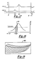
find line circuit 170. The find line circuit is also furnished with a threshold value against which the incoming digital video data is compared. Figures 17 and 18 illustrate what happens conceptually in the find line circuit. Figure 17 depicts the two arbitrary scan lines SCAN 1 andSCAN 2 of Figure 16. Both scan lines reach an intensity peak at a given pixel location corresponding to the intersection of the scan line with thecontour line 38. In the example of Figure 17,SCAN 1 intersects atpixel 230 whileSCAN 2 intersects atpixel 200. This indicates thatSCAN 2, having a lower pixel intersection number, is closer to the sensor module thanSCAN 1. - Figure 18 is an enlargement of either
SCAN 1 orSCAN 2. The threshold value input over the bus to the find line circuit is illustrated as a horizontal dashed line. Once the intensity level exceeds the threshold, a predetermined number of consecutive pixels above the threshold are counted before the intersection is declared to be found. This predetermined number is input from the bus to the find line circuit as value n in Figure 15. Assuming n = 4, the declaredintersection point 172 is the fourth consecutive pixel above the threshold. This declared intersection point would correspond to a value of 230 for theexemplary SCAN 1 and a value of 200 for theexamplary SCAN 2. - This declared intersection point is then strobed into a min-
max accumulator 174 along with the scan line number. The min-max accumulator compares the input declared intersection point value with an initialized value, determined by set-up block 176 or with a previously stored value. If the newly input intersection point value is smaller than the stored value, the newly input intersection point value and its corresponding scan line number is stored in the min-max accumulator. If the intersection point value is not smaller than the stored value, the newly input value is discarded and the existing stored value remains. In this fashion, as each scan line occurs, the min-max accumulator automatically retains the row and column location of the intersection corresponding to the point closest to the sensor module. After the video frame is completed, the row and column value stored in the min-max accumulator is written to atransition register 178. The transition register may be read by the processor to quickly determine the probable location of the point closest to the sensor module. A window may then be conceptually drawn around this point so that further computation can focus on the crucial portion of the contour line. Seewindow 180 in Figure 16. - As mentioned above, it is possible that the portion of the crown in the tire sidewall may have raised lettering thereon. The presently preferred embodiment employs an algorithm to ignore the raised lettering and to instead locate the plane of the tire sidewall in relation to the portion which does not contain lettering. This is accomplished by allowing the video camera to accumulate intensity readings over an entire wheel revolution. Figure 20 compares the illumination intensity return from a tire without raised lettering (curve A) with three different possible returns caused when raised lettering is present. Curve B exemplifies a return from the raised lettering which is lower in intensity than the return from the tire sidewall. Curve C exemplifies the case in which the return from the raised lettering and from the sidewall are approximately equal in intensity. Curve D exemplifies the situation in which there is no appreciable drop-off in intensity due to a gap between raised lettering and the tire sidewall. In every case, because the plane of the raised lettering is closer to the sensor module than the plane of the sidewall, light reflected from the raised lettering will appear closer to the
origin 0 in Figure 20. The invention advantageously utilizes this fact to locate a point (used to represent tire location) which lies on the portion of the intensity curve to the left of the leftmost peak and which is thus not based on any intensity return from raised lettering. - One presently preferred technique for accomplishing this is illustrated in Figure 20. Figure 20 depicts a double-peaked return; the higher intensity peak corresponds to the return from the sidewall body and the lower intensity peak (closer to the origin 0) corresponds to the return from the raised lettering. The processor evaluates individual pixel values starting from a position farthest from the
origin 0 and determines where the value ceases to rise and hence has reachedfirst intensity peak 182. All pixel data beyond this point is ignored and a center of gravity calculation is performed to find the center ofgravity 184 of the data occurring on the side of the intensity peak farthest from theorigin 0. The center of gravity may be calculated by multiplying the intensity value with the row position value D of each point, summing all values so calculated, and dividing the sum by the sum of the intensities of those points. This calculation gives an average row position dl which can be used to represent the location of the portion of the tire sidewall closest to the sensor module. By such a calculation, the effects of any raised lettering are eliminated. Although the center of gravity may not in fact represent the point of closest proximity to the sensor, the same center of gravity calculation is performed at all angular positions around the circumference of the tire and gives good, consistent results. - Another technique for locating the closest point on the tire while ignoring raised lettering, may be to simply count a predetermined number of pixels past the threshold crossing point and use those points to do a center of gravity calculation. The center of gravity calculation gives a repeatable data point at sub-pixel resolution. The number of pixels counted should be selected so that the datum point does not fall in the region of raised lettering.
- A third technique for determining the point of closest proximity is to select the point which represents the greatest rate of change of intensity information on the upside of the first peak.
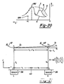
- The point of closest proximity is calculated by one of the above methods for each scan line within the
window 180. Figure 19 conceptually illustrates each of the closest proximity points of consecutive scan lines withinwindow 180. The processor then determines a final value by averaging a plurality of these closest proximity points, and that average value is used to represent one data point on the surface of the tire as measured by one of the sensor modules. A similar process is performed for the other sensor module or modules, giving two points at different radially equivalent locations on the tire through which a line may be drawn for toe-in calculations. A third point may be similarly determined from which camber can be checked. - The data points discussed so far represent row and column values in the video frame (image space). In order to relate these row and column values to points in real space, a rectification table or lookup table may be used. A rectification table is a lookup table in processor memory which has been previously filled with values during calibration, mapping image space to real space. Image space values which occur between recorded values in the lookup table are converted into real space coordinates by interpolation.
- While a rectification table of this type may be used, the presently preferred embodiment employs a fifth order polynomial equation which gives real space coordinates as a function of image space coordinates. The polynomial function may be determined by measuring multiple data points of known real space location in a manner used to fill a lookup table. The values are then operated on by a curve fitting algorithm to provide a polynomical equation. A fifth order polynomial equation has been found to give good results, although other types of equations may also be useful in certain applications.
- Once two points in real space have been found, corresponding to two points along a horizontal line on the tire, the toe-in is easily computed using trigonometry. Referring to Figure 21, the left and
right sensor modules 36 are illustrated together with a portion of thetire 12. Each sensor is a predetermined distance from a reference point REF. The distances are designated YL and YR. The spacing between the left and right data points PL and PR is therefore YL + YR. The real space position of points PL and PR in the Z direction are the measured values ZL and ZR determined by the conversion from image space data to real space data. If the points PL and PR do not have the same Z coordinates, then there is a nonzero toe-in angle. This angle is determined by trigonometry as the arc tangent of the difference (ZR - ZL) divided by the sum (YR + YL). - Once this toe-in angle has been computed, it may be compared with preestablished tolerances for quality control checking. The angle may also be fed to the digital to analog converter board 98 (Figure 8) for conversion into an analog signal for driving the
alignment meters 50. In the presently preferred embodiment, the meters are driven in a nonlinear fashion whereby the greatest accuracy is achieved when the toe-in angle nears zero. When the toe-in angle is far from zero, the meter sensitivity is decreased to that comparatively large changes in toe-in can be made without similarly large excursions of the alignment meter. Once the toe-in angle approaches the proper setting, the sensitivity of the meter is increased so that a precise setting can be made. - The preferred embodiment has been described in an application where the toe-in alignment is measured by finding two points along a horizontal line on the tire. It will be understood, however, that comparable results can be achieved by projecting structured light to illuminate contour lines lying generally along a line which forms a nonperpendicular angle with the horizontal. For example, the structured light can be projected to illuminate contour lines which lie on a line disposed 45 degrees with respect to the horizontal. In such a case, the resulting data can be broken down into a horizontal component and a vertical component. The horizontal component can be used to calculate the toe-in alignment and the vertical component can be used to calculate the camber. By steering the wheel to determine the plane of the wheel in two steered orientations, the caster can also be determined. Thus the invention is capable of determining toe-in, camber and caster from a single pair of contour lines. In the present embodiment, this can be accomplished using two sensor modules positioned to illuminate two contour lines disposed along a diagonal relative to the horizontal. This is illustrated in Figure 24 where the diagonal line is indicated at D and the contour lines are indicated at 38.
- The present invention provides considerably more resolution and accuracy than the analog meter is capable of conveying. Thus the digital data provided by the apparatus may be used in critical applications, such as providing audit data for quality control purposes or for driving robotic wheel alignment equipment. Digital readouts may also be used in place of the analog meter. The analog meter is presently preferred because it provides a simple to understand computer-to-human interface. Combinations of analog and digital readouts may also be employed.
- While the invention has been described largely in connection with a toe-in alignment system, the invention is capable of measuring camber, caster and other aspects of alignment, including vehicle body alignment and front and rear wheel alignment using the techniques described herein.
- While the invention has been described in connection with its presently preferred embodiment, it will be understood that the invention is capable of certain modification and change without departing from the spirit of the invention as set forth in the appended claims.
Claims (22)
- A non-contact system for measuring a predetermined alignment characteristic of a wheel (10) of a vehicle (28), comprising:- light source means for projecting along an axis light directed to said wheel (10);- optical sensor means positioned at a perspective angle (48) relative to said axis of said projected light for receiving diffusely reflected light directed from said wheel (10), and converting said reflected light to corresponding electrical signals; and- processor means (76, 78) for processing said electrical signals and calculating therefrom a signal depending on said predetermined alignment characteristic of said wheel (10),
characterized by- said light source means projecting a geometrically structured light pattern directly onto said wheel (10) to create a predetermined feature on the surface of said wheel;- said optical sensor means receiving a reflected image of said predetermined feature; and- said processor means (76, 78) measuring the relative position of the surface of the wheel in three-dimensional space and calculating therefrom said predetermined alignment charac- teristic of said wheel (10). - The system of claim 1, characterized in that said light source means comprises a laser-based light source (54).
- The system of claim 1, characterized in that said processor means (76, 78) calculates from said electrical signals the place of said wheel (10) for determining said predetermined alignment characteristic and provides an output signal related thereto.
- The system of any of claims 1 through 3, characterized by adjustment means for adjusting said predetermined alignment characteristic of said wheel (10) in accordance with said output signal.
- The system of any of claims 1 through 4, characterized in that it is suitable for a vehicle (28) having two front steerable wheels (10) and that:- said light source means includes first light source means for projecting a geometrically structured light pattern onto one of said two front wheels (10), and- second light source means for projecting a geometrically structured light pattern onto the other of said two front wheels (10);- said optical sensor means includes first optical sensor means for receiving the reflected image of said geometrically structured light pattern of said one front wheel (10) and converting said reflected image to corresponding electrical signals; and- said processor means (76, 78) processes said electrical signals and calculates therefrom the plane (C) of said one front wheel (10) and the plane (C) of said other front wheel (10) and determines therefrom said predetermined alignment characteristic of said two front wheels (10).
- The system of any of claims 1 through 5, characterized in that:- said light source means projects a geometrically structured light pattern onto the wheel (10) of the vehicle (28) so that at least two radially equivalent points on said wheel (10) are illuminated thereby; and- said processor means (76, 78) processes said electrical signals and identifies the position of said two radially equivalent points in three-dimensional space and determines therefrom said predetermined alignment characteristic of said wheel (10).
- The system of claim 6, characterized in that said two radially equivalent points define a chord having a horizontal component and said predetermined alignment characteristic comprises the toe-in of the wheel (10).
- The system of claim 6, characterized in that said two radially equivalent points define a chord having a vertical component and said predetermined alignment characteristic comprises the camber of the wheel (10).
- The system of any of claims 1 through 8, characterized in that it is suitable for a wheel (10) of a vehicle (28) having a tire (12) mounted thereon, and that:- said light source means comprises a first laser source (54) for projecting a plane of light so that a first line image (38) appears on the sidewall of said tire (12), and a second laser source (54) for projecting a second plane of light so that a second line image (38) appears on the sidewall of said tire (12);- said optical sensor means comprises a first optical sensor for receiving the reflected light from said first line image (38) of said tire sidewall and producing electrical signals in response thereto corresponding to the intensity of the received light, and a second optical sensor for receiving the reflected light from said second line image (38) of said tire sidewall and producing electrical signals in response thereto corresponding to the intensity of the received light; and- said processor means processes said electrical signals, identifies the location in three-dimensional space of a first point from said first line image (38), identifies the location in three-dimensional space of a second point from said second line image (38) radially equivalent to said first point, calculates therefrom the plane (C) of said tire (12), and determines therefrom said predetermined alignment characteristic of said wheel (10).
- The system of claim 9, characterized by means for rotating said tire (12) at a predetermined speed, said first and second optical sensors being adapted to produce electrical signals relating to the cumulative amount of light received over a predetermined period of time corresponding substantially to the period of one revolution of said tire (12).
- The system of any of claims 6 through 10, characterized in that it is suitable for a wheel (10) of a vehicle (28) which is a steerable wheel (10) having associated therewith a steering axis, and further including:- means for turning said steerable wheel (10) about said steering axis from a first position to a second position; and further- wherein said processor means identifies the positions in three-dimensional space of said two radially equivalent points when said wheel (10) is in both of said first and second positions, calculates therefrom the plane (A, B) of said wheel (10) in each of said first and second positions and the line of intersection between said two planes (A, B), and determines therefrom the caster of said wheel (10).- said processor means (76, 78) measuring the relative position of the surface of the wheel in three-dimensional space and calculating therefrom said predetermined alignment characteristic of said wheel (10).
- A method of measuring a predetermined alignment characteristic of a wheel (10) of a vehicle (28), characterized by the steps of:- projecting a geometrically structured light pattern directly onto the wheel (10) of the vehicle (28) to create a predetermined feature on the surface of the wheel;- sensing the reflected image of said predetermined feature from the light diffusely reflected off of said wheel (10) and converting said sensed light image to corresponding electrical signals in accordance with the intensity of the diffusely reflected light; and- determining in accordance with said electrical signals the location in three-dimensional space of selected points from said predetermined feature and calculating therefrom said predetermined alignment characteristic.
- The method of claim 12, characterized by the step of calculating the plane (C) of said wheel (10) in three-dimensional space.
- The method of claim 12 or 13, characterized in that said selected points correspond to radially equivalent points on said wheel (10).
- The method of any of claims 12 through 14, characterized by the step of adjusting said predetermined alignment characteristic of said wheel (10) in accordance with said calculated measurement.
- The method of any of claims 12 through 15 wherein the vehicle (28) has two front steerable wheels (10), characterized by the steps of:- projecting a first geometrically structured light pattern onto one of said two front wheels (10);- projecting a second geometrically structured light pattern onto the other of said two front wheels (10);- sensing the reflected light images of said first and second structured light patterns off of said two front wheels (10) and producing corresponding electrical signals in accordance with the intensity of said sensed light; and- determining in accordance with said electrical signals the location in three-dimensional space of selected points in the reflected light images of said first and second structured light patterns and calculating therefrom said predetermined alignment characteristic.
- The method of any of claims 12 through 16, wherein the wheel (10) of the vehicle (28) has a tire (12) mounted thereon, characterized by the steps of:- projecting a geometrically structured light pattern onto the sidewall of the tire (12);- sensing the reflected image of said geometrically structured light pattern from the light reflected off of said tire sidewall and producing electrical signals in accordance with the intensity of said sensed light;- identifying the location in three-dimensional space of at least two points in said reflected image corrsponding to radially equivalent points on said tire sidewall; and- calculating from said two points the plane of said tire sidewall and determining therefrom said predetermined alignment characteristic of said wheel (10).
- The method of claim 17, characterized by the steps of:- rotating the tire (12) of the vehicle (28) at a predetermined speed;- sensing the reflected image of said geometrically structured light pattern off of said tire sidewall over a period of time corresponding substantially to the period of one revolution of said tire (12) and producing electrical signals in accordance with the intensity of the accumulated total of light received over said period of time; and- determining from said electrical signals the location in three-dimensional space of selected points in said light pattern and calculating therefrom said predetermined alignment characteristics.
- The method of any of claims 12 through 18 wherein the wheel (10) is a steerable wheel having associated therewith a steering axis, characterized by the steps of:- positioning said steerable wheel (10) in a first position;- projecting a geometrically structured light pattern onto said wheel (10) so as to illuminate at least two radially equivalent points on either side of said steering axis;- sensing the reflected light image of said geometrically structured light pattern of said wheel (10) in said first position and producing first electrical signals corresponding to the intensity of the received light;- turning said steerable wheel (10) about said steering axis from said first position to a second position;- projecting said geometrically structured light pattern onto said wheel (10) so as to illuminate at least two radially equivalent points on either side of said steering axis;- sensing the reflected image of said geometrically structured light pattern off of said wheel (10) in said second position and producing second electrical signals corresponding to the intensity of the received light;- identifying in accordance with said first electrical signals the positions in three-dimensional space of said two radially equivalent points and calculating therefrom the plane (A, B) of the wheel (10) in said first position;- identifying in accordance with said second electrical signals the positions in three-dimensional space of said two radially equivalent points and calculating therefrom the plane (A, B) of said wheel in said second position; and- determining the line of intersection between said two planes (A, B) and determining therefrom the caster of said wheel (10).
- The method of any of claims 12 through 19, characterized by the steps of:- projecting geometrically structured light in at least one plane onto the surface of a member structurally integral with said wheel (10) to illuminate at least two contour lines (38) on different portions of said member structurally integral with said wheel (10);- optically reading each of said contour lines (38) using an optical sensor disposed at a viewing angle (48) offset from the plane of said structured light and collecting data points indicative of the position of said contour lines (38);- locating at least one datum point associated with each of said contour lines (38) which corresponds to a radially equivalent portion of the surface of said wheel (10); and- using said datum points to determine the position of said wheel (10) and providing an indication to an operator of said wheel position relative to a desired position.
- The method of claim 20, characterized by the step of adjusting the position of said wheel (10) based on said indication in order to bring said wheel (10) into alignment with said desired position.
- The method of any of claims 12 through 21, characterized by the steps of:- reflecting geometrically structured light from at least two points on said wheel (10) while rotating said wheel (10);- using at least one video camera (72) to gather light reflected from said two points while said wheel (10) is rotated to accumulate a signal indicative of the quantity of light gathered;- from said video camera (72) periodically reading electrical data indicative of said accumulated signal; and- using said electrical data to determine the spatial position of said two points and to thereby determine the position of said wheel (10).
Applications Claiming Priority (2)
| Application Number | Priority Date | Filing Date | Title |
|---|---|---|---|
| US07/015,943 US4745469A (en) | 1987-02-18 | 1987-02-18 | Vehicle wheel alignment apparatus and method |
| US15943 | 1987-02-18 |
Publications (2)
| Publication Number | Publication Date |
|---|---|
| EP0280941A1 EP0280941A1 (en) | 1988-09-07 |
| EP0280941B1 true EP0280941B1 (en) | 1992-11-19 |
Family
ID=21774463
Family Applications (1)
| Application Number | Title | Priority Date | Filing Date |
|---|---|---|---|
| EP88102006A Expired - Lifetime EP0280941B1 (en) | 1987-02-18 | 1988-02-11 | Vehicle wheel alignment apparatus and method |
Country Status (5)
| Country | Link |
|---|---|
| US (1) | US4745469A (en) |
| EP (1) | EP0280941B1 (en) |
| JP (1) | JPH0781853B2 (en) |
| CA (1) | CA1294427C (en) |
| DE (1) | DE3875984T2 (en) |
Cited By (2)
| Publication number | Priority date | Publication date | Assignee | Title |
|---|---|---|---|---|
| DE19717569A1 (en) * | 1997-04-25 | 1998-10-29 | Hofmann Werkstatt Technik | Method and device for determining the wheel position of a wheel mounted on a vehicle |
| US11713064B1 (en) * | 2022-09-20 | 2023-08-01 | Bnsf Railway Company | System and method for detecting axle body and filet cracks in rail vehicles |
Families Citing this family (93)
| Publication number | Priority date | Publication date | Assignee | Title |
|---|---|---|---|---|
| JPS6394103A (en) * | 1986-10-07 | 1988-04-25 | Yasaka Seiki Kk | Method and device for measuring wheel alignment |
| US4899218A (en) * | 1987-02-18 | 1990-02-06 | Perceptron, Inc. | Vehicle wheel alignment apparatus and method |
| US4856199A (en) * | 1987-02-18 | 1989-08-15 | Merrill Engineering Laboratories, Inc. | Single contact point distance measuring for plane determination |
| US5027275A (en) * | 1987-11-30 | 1991-06-25 | Mazda Motor Corporation | Method for toe angle adjustment for a vehicle and a toe angle adjusting apparatus therefor |
| US4977524A (en) * | 1989-01-03 | 1990-12-11 | Hunter Engineering Company | Electronic measuring gauge and apparatus for accurate vehicle stance diagnosis and guidance in effecting wheel alignment |
| US5048954A (en) * | 1989-07-07 | 1991-09-17 | Miradco | Laser-based wheel alignment system |
| US5111585A (en) * | 1989-11-21 | 1992-05-12 | Iyasaka Seiki Co., Ltd. | Method and apparatus for measuring and adjusting the wheel alignment of automotive vehicles |
| US5054918A (en) * | 1990-02-02 | 1991-10-08 | Fmc Corporation | Light scanning system for measurement of orientation and physical features of a workpiece |
| DE4134411C2 (en) † | 1991-10-17 | 1997-01-16 | Hofmann Werkstatt Technik | Method and device for measuring wheel positions on a motor vehicle |
| US5206720A (en) * | 1991-12-16 | 1993-04-27 | Bridgestone Corporation | Apparatus and technique for monitoring component position during tire building |
| US5208646A (en) * | 1991-12-20 | 1993-05-04 | Fmc Corporation | Wheel alignment system |
| FR2695998A1 (en) * | 1991-12-20 | 1994-03-25 | Fmc Corp | Wheel alignment system for measuring alignment angles of wheels |
| CA2086449C (en) * | 1992-01-06 | 2000-03-07 | Steven W. Rogers | Computer interface board for electronic automotive vehicle service |
| DE4212426C1 (en) * | 1992-04-14 | 1993-07-01 | Wolfgang 3407 Gleichen De Brunk | Measurement of tracking and camber of vehicle wheel axles - recording markers on rotating wheels using synchronised video cameras, image evaluation of marker positions |
| US7983817B2 (en) * | 1995-06-07 | 2011-07-19 | Automotive Technologies Internatinoal, Inc. | Method and arrangement for obtaining information about vehicle occupants |
| DE4217702A1 (en) * | 1992-05-24 | 1993-11-25 | Vision Tools Bildanalyse Syste | Vehicle contactless wheel centre, camber and tracking measurement - using mobile CCD cameras and illumination to produce symmetrical image or images. |
| US5724743A (en) * | 1992-09-04 | 1998-03-10 | Snap-On Technologies, Inc. | Method and apparatus for determining the alignment of motor vehicle wheels |
| EP0674759B1 (en) | 1992-09-04 | 2001-07-18 | Snap-on Technologies, Inc. | Method and apparatus for determining the alignment of motor vehicle wheels |
| US5532816A (en) * | 1994-03-15 | 1996-07-02 | Stellar Industries, Inc. | Laser tracking wheel alignment measurement apparatus and method |
| SE503707C2 (en) * | 1994-10-24 | 1996-08-05 | Combitech Traffic Syst Ab | Device for identification of vehicles at a checkpoint |
| US5583797A (en) * | 1994-11-03 | 1996-12-10 | Ford Motor Company | Method and apparatus for wheel alignment audit |
| US5600435A (en) * | 1995-05-24 | 1997-02-04 | Fori Automation, Inc. | Intelligent sensor method and apparatus for an optical wheel alignment machine |
| DE19528798C2 (en) * | 1995-08-04 | 2000-04-20 | Schenck Pegasus Gmbh | Device for the contactless determination of the level on a motor vehicle |
| US5675515A (en) * | 1995-12-28 | 1997-10-07 | Hunter Engineering Company | Apparatus and method for determining vehicle wheel alignment measurements from three dimensional wheel positions and orientations |
| US6298284B1 (en) | 1995-12-28 | 2001-10-02 | Hunter Engineering Company | Apparatus and method with improved field of view for determining vehicle wheel alignment measurements from three dimensional wheel positions and orientations |
| US5724128A (en) * | 1995-12-28 | 1998-03-03 | Hunter Engineering Company | Apparatus and method for determining vehicle wheel alignment measurements from three dimensional wheel positions and orientations |
| EP0803703B1 (en) * | 1996-04-23 | 2002-07-24 | G.S. S.r.l. | A method of determining vehicle wheel alignment |
| DE19623982C1 (en) * | 1996-06-15 | 1997-09-04 | Froude Hofmann Prueftechnik Gm | Apparatus to check vehicle front wheel toe=in angles |
| US5703796A (en) * | 1996-07-11 | 1997-12-30 | Ford Global Technologies, Inc. | Driveline alignment apparatus and method |
| US5978077A (en) * | 1996-10-31 | 1999-11-02 | Fori Automation, Inc. | Non-contact method and apparatus for determining camber and caster of a vehicle wheel |
| SE510343C2 (en) * | 1996-12-20 | 1999-05-17 | Volvo Lastvagnar Ab | A method for measuring the orientation of a surface relative to a geometric reference |
| US6100923A (en) * | 1997-03-20 | 2000-08-08 | The United States Of America As Represented By The Secretary Of The Army | Method of infrared imaging |
| DE19757760A1 (en) * | 1997-12-23 | 1999-07-01 | Bosch Gmbh Robert | Device for determining the wheel and / or axle geometry of motor vehicles |
| US6151562A (en) * | 1998-07-24 | 2000-11-21 | Merrill; M. Stanley | Vehicle wheel alignment data by rotating vision sensor |
| US7065462B2 (en) * | 1998-07-24 | 2006-06-20 | Merilab, Inc. | Vehicle wheel alignment by rotating vision sensor |
| EP0994329A1 (en) * | 1998-10-14 | 2000-04-19 | VisiCon Automatisierungstechnik GmbH | Calibration of a device used for the alignment of vehicle wheels |
| JP3197529B2 (en) * | 1999-02-10 | 2001-08-13 | 安全自動車株式会社 | Non-contact measurement method of wheel alignment characteristics and its measurement device |
| US6413084B1 (en) | 2000-04-28 | 2002-07-02 | Ora Metrix, Inc. | Method and system of scanning |
| US7068836B1 (en) | 2000-04-28 | 2006-06-27 | Orametrix, Inc. | System and method for mapping a surface |
| US6728423B1 (en) | 2000-04-28 | 2004-04-27 | Orametrix, Inc. | System and method for mapping a surface |
| US6532299B1 (en) | 2000-04-28 | 2003-03-11 | Orametrix, Inc. | System and method for mapping a surface |
| US6771809B1 (en) | 2000-04-28 | 2004-08-03 | Orametrix, Inc. | Method and system for registering data |
| US6744932B1 (en) | 2000-04-28 | 2004-06-01 | Orametrix, Inc. | System and method for mapping a surface |
| US7068825B2 (en) * | 1999-03-08 | 2006-06-27 | Orametrix, Inc. | Scanning system and calibration method for capturing precise three-dimensional information of objects |
| US6744914B1 (en) | 2000-04-28 | 2004-06-01 | Orametrix, Inc. | Method and system for generating a three-dimensional object |
| WO2000060308A1 (en) | 1999-03-30 | 2000-10-12 | Siemens Aktiengesellschaft | Method for adjusting the axle geometry of a vehicle and adjusting device and production line for carrying out said method |
| JP2001004344A (en) | 1999-06-25 | 2001-01-12 | Anzen Motor Car Co Ltd | Alignment measuring device for vehicle wheel |
| US6626073B1 (en) | 1999-07-07 | 2003-09-30 | Hennessy Industries, Inc. | On car brake lathe aligning apparatus |
| DE10019386C2 (en) * | 2000-04-19 | 2003-04-03 | Bernward Maehner | Method and device for testing tires |
| JP4206213B2 (en) * | 2000-04-28 | 2009-01-07 | オラメトリックス インコーポレイテッド | Method and system for scanning a surface and creating a three-dimensional object |
| US7027642B2 (en) * | 2000-04-28 | 2006-04-11 | Orametrix, Inc. | Methods for registration of three-dimensional frames to create three-dimensional virtual models of objects |
| US6724489B2 (en) * | 2000-09-22 | 2004-04-20 | Daniel Freifeld | Three dimensional scanning camera |
| US6661505B2 (en) * | 2001-06-28 | 2003-12-09 | Snap-On Technologies, Inc. | Method and system for measuring caster trail |
| US6894771B1 (en) | 2002-05-15 | 2005-05-17 | Hunter Engineering Company | Wheel alignment apparatus and method utilizing three-dimensional imaging |
| US6728609B2 (en) | 2002-09-16 | 2004-04-27 | Snap-On Technologies, Inc. | Diagnostic method and system for a multiple-link steering system |
| US8306696B2 (en) * | 2003-04-17 | 2012-11-06 | Driveright Holdings, Ltd. | Method and system for aligning a vehicle with an artificial horizon |
| DE10335829A1 (en) * | 2003-08-05 | 2005-03-10 | Siemens Ag | Method for determining the axle geometry and sensor for carrying it out |
| US7382913B2 (en) * | 2003-08-22 | 2008-06-03 | Hunter Engineering Company | Method and apparatus for guiding placement of vehicle service fixtures |
| DE102004026563B4 (en) * | 2004-05-27 | 2007-11-15 | Siemens Ag | Measuring device for geometric data of the chassis of a motor vehicle with means for automatic adaptation to the vehicle-mounted wheel type |
| US7538864B2 (en) * | 2005-03-24 | 2009-05-26 | Hunter Engineering Company | Vehicle wheel alignment system scanned beam imaging sensor |
| CN101175971B (en) * | 2005-05-13 | 2010-06-16 | 斯耐普昂公司 | Wheel aligner measurement module attachment system |
| DE102005051737A1 (en) * | 2005-10-28 | 2007-05-03 | Daimlerchrysler Ag | Functional testing method e.g. for system consisting of multiple electrical or electronic components, involves having inspection fixture designed as robots, function which can be examined is released |
| DE102005063082A1 (en) * | 2005-12-29 | 2007-07-05 | Robert Bosch Gmbh | Vehicle chassis optical measurement method, involves extracting surface profiles from scanned surface structure, and determining spatial position characteristic of surface points as position data to determine chassis data |
| DE102005063051A1 (en) * | 2005-12-29 | 2007-07-05 | Robert Bosch Gmbh | Motor vehicle`s e.g. car, chassis measuring method, involves disposing coordinate system for image recording device e.g. camera, and/or measuring unit to determine chassis data of evaluation unit independent of reference objects |
| DE102005063083A1 (en) * | 2005-12-29 | 2007-07-05 | Robert Bosch Gmbh | Optical chassis measurement method for use at test station, involves adapting sizes of object section after localization of interested object structures to different vehicle types and rim sizes |
| US7654678B1 (en) | 2006-02-19 | 2010-02-02 | Runco International, Llc | Cinewide with autoscope |
| DE202007001016U1 (en) * | 2006-07-19 | 2007-06-06 | Snap-On Equipment Gmbh | Roller brake tester |
| DE102006036671A1 (en) * | 2006-08-03 | 2008-02-07 | Dürr Assembly Products GmbH | Method for determining the axle geometry of a vehicle |
| DE102006048725A1 (en) * | 2006-10-16 | 2008-04-17 | Robert Bosch Gmbh | Method for determining the axis of rotation of a vehicle wheel |
| JP2008107194A (en) * | 2006-10-25 | 2008-05-08 | Iyasaka Seiki Kk | Wheel alignment measuring device for vehicle |
| DE102007003086A1 (en) * | 2007-01-16 | 2008-07-17 | Dürr Assembly Products GmbH | Device for measuring the chassis geometry |
| US7864309B2 (en) | 2007-05-04 | 2011-01-04 | Burke E. Porter Machinery Company | Non contact wheel alignment sensor and method |
| DE102007021328A1 (en) * | 2007-05-07 | 2008-11-13 | Robert Bosch Gmbh | Method and device for wheel alignment |
| DE102007047424A1 (en) | 2007-10-04 | 2009-04-09 | Robert Bosch Gmbh | Automotive component surveying system, use and method |
| DE102008006329A1 (en) | 2008-01-28 | 2009-07-30 | Robert Bosch Gmbh | Method and device for checking the referencing of measuring heads of a chassis measuring system |
| DE102008046104A1 (en) * | 2008-09-05 | 2010-03-11 | Maha Maschinenbau Haldenwang Gmbh & Co. Kg | Device for track measurement of vehicle in e.g. brake test stand, has receiving element for detecting position mark on wheel, and control unit determining track value based on evaluated data, where mark is produced on inner side of wheel |
| DE102008042018A1 (en) * | 2008-09-12 | 2010-03-18 | Robert Bosch Gmbh | Method for adjusting or calibrating a vehicle surroundings sensor and vehicle surroundings sensor adjustment or calibration arrangement |
| DE102008042145A1 (en) | 2008-09-17 | 2010-03-18 | Robert Bosch Gmbh | Method and measuring arrangement for determining the wheel or axle geometry of a vehicle |
| CN102901457B (en) * | 2012-10-18 | 2015-04-15 | 北京航空航天大学 | Dynamic measurement method and system for train wheel diameter |
| US9665793B2 (en) | 2013-03-15 | 2017-05-30 | Hunter Engineering Company | Method for determining parameters of a rotating object within a projected pattern |
| DE102013207374A1 (en) * | 2013-04-23 | 2014-10-23 | Robert Bosch Gmbh | Device and method for recognizing labels on vehicle tires |
| ITBO20130697A1 (en) | 2013-12-19 | 2015-06-20 | Corghi Spa | APPARATUS AND DIAGNOSTIC ASSESSMENT METHOD OF A VEHICLE STRUCTURE |
| US10222455B1 (en) | 2014-09-05 | 2019-03-05 | Hunter Engineering Company | Non-contact vehicle measurement system |
| US10068389B1 (en) | 2014-10-24 | 2018-09-04 | Hunter Engineering Company | Method and apparatus for evaluating an axle condition on a moving vehicle |
| US9779560B1 (en) | 2014-11-25 | 2017-10-03 | Hunter Engineering Company | System for multi-axis displacement measurement of surfaces on a moving vehicle |
| US10697766B1 (en) | 2014-11-25 | 2020-06-30 | Hunter Engineering Company | Method and apparatus for compensating vehicle inspection system measurements for effects of vehicle motion |
| US10408610B1 (en) | 2015-07-30 | 2019-09-10 | Hunter Engineering Company | Method and system for displacement measurement of surfaces on a moving vehicle |
| US10240916B1 (en) | 2016-01-05 | 2019-03-26 | Hunter Engineering Company | Method and apparatus for calibrating an inspection system for moving vehicles |
| US10475201B1 (en) | 2016-02-02 | 2019-11-12 | Hunter Engineering Company | Method and apparatus for determining wheel rim and tire dimensions on a moving vehicle |
| DE102016112712A1 (en) | 2016-07-12 | 2018-01-18 | Dürr Assembly Products GmbH | Method for determining parameters of the chassis geometry of wheels of a non-steered axle, use of the method, test bench for a vehicle and a measuring unit |
| EP3296688A1 (en) | 2016-09-20 | 2018-03-21 | VisiCon Automatisierungstechnik GmbH | Method and device for stereo photogrammetric measurement of different objects |
| WO2018054888A1 (en) | 2016-09-20 | 2018-03-29 | Visicon Automatisierungstechnik Gmbh | Method and device for the stereo photogrammetric measurement of different objects |
| AT521309B1 (en) * | 2018-06-13 | 2020-10-15 | Avl List Gmbh | PROCEDURE AND MEASURING ARRANGEMENT FOR THE OPTICAL DETERMINATION OF CHASSIS PARAMETERS |
Family Cites Families (10)
| Publication number | Priority date | Publication date | Assignee | Title |
|---|---|---|---|---|
| US4109387A (en) * | 1976-12-29 | 1978-08-29 | Hitachi, Ltd. | Position detecting apparatus |
| DE2727420A1 (en) * | 1977-06-18 | 1979-01-04 | Ver Flugtechnische Werke | Vehicle wheel camber and alignment measuring equipment - operates with simple calibration using light beams impinging on tolerance displays |
| US4130362A (en) * | 1977-09-19 | 1978-12-19 | Fmc Corporation | Apparatus for determining steering positions of the front wheels of a vehicle |
| US4319838A (en) * | 1979-10-01 | 1982-03-16 | Hunter Engineering Company | Vehicle wheel alignment apparatus |
| DE2948573A1 (en) * | 1979-12-03 | 1981-06-04 | Siemens AG, 1000 Berlin und 8000 München | Contactless measurement of vehicle wheel and steering geometry - uses electronic evaluation of elliptical video images of wheels |
| DE3143173C2 (en) * | 1981-10-30 | 1984-04-12 | Automation W + R GmbH, 8000 München | Measuring arrangement for measuring the angular position of an object to be measured using the reflection method |
| US4639878A (en) * | 1985-06-04 | 1987-01-27 | Gmf Robotics Corporation | Method and system for automatically determining the position and attitude of an object |
| US4647208A (en) * | 1985-07-22 | 1987-03-03 | Perceptron, Inc. | Method for spatial measurement of holes |
| DE3526923A1 (en) * | 1985-07-27 | 1987-02-05 | Man Technologie Gmbh | METHOD AND DEVICE FOR CONTACTLESS DETERMINATION OF SURFACES |
| JPH0625661B2 (en) * | 1986-07-02 | 1994-04-06 | 日産自動車株式会社 | Wheel alignment measurement method for automobiles |
-
1987
- 1987-02-18 US US07/015,943 patent/US4745469A/en not_active Expired - Lifetime
-
1988
- 1988-01-28 CA CA000557562A patent/CA1294427C/en not_active Expired - Lifetime
- 1988-02-11 DE DE8888102006T patent/DE3875984T2/en not_active Ceased
- 1988-02-11 EP EP88102006A patent/EP0280941B1/en not_active Expired - Lifetime
- 1988-02-18 JP JP63036437A patent/JPH0781853B2/en not_active Expired - Lifetime
Cited By (2)
| Publication number | Priority date | Publication date | Assignee | Title |
|---|---|---|---|---|
| DE19717569A1 (en) * | 1997-04-25 | 1998-10-29 | Hofmann Werkstatt Technik | Method and device for determining the wheel position of a wheel mounted on a vehicle |
| US11713064B1 (en) * | 2022-09-20 | 2023-08-01 | Bnsf Railway Company | System and method for detecting axle body and filet cracks in rail vehicles |
Also Published As
| Publication number | Publication date |
|---|---|
| JPS63247606A (en) | 1988-10-14 |
| CA1294427C (en) | 1992-01-21 |
| US4745469A (en) | 1988-05-17 |
| DE3875984T2 (en) | 1993-04-01 |
| JPH0781853B2 (en) | 1995-09-06 |
| DE3875984D1 (en) | 1992-12-24 |
| EP0280941A1 (en) | 1988-09-07 |
Similar Documents
| Publication | Publication Date | Title |
|---|---|---|
| EP0280941B1 (en) | Vehicle wheel alignment apparatus and method | |
| US4899218A (en) | Vehicle wheel alignment apparatus and method | |
| US5731870A (en) | Intelligent sensor method and apparatus for an optical wheel alignment machine | |
| EP1295086B1 (en) | Glint-resistant position determination system | |
| US6915228B2 (en) | Method and device for calibrating an image sensor system in a motor vehicle | |
| EP0674759B1 (en) | Method and apparatus for determining the alignment of motor vehicle wheels | |
| US6397164B1 (en) | Device for determining the wheel and/or axle geometry of motor vehicles | |
| EP0927335B1 (en) | Calibrating cameras used in alignment of wheels | |
| EP0880677B1 (en) | Method and apparatus for determining the alignment of motor vehicle wheels | |
| US6526665B2 (en) | Glint-resistant position determination system | |
| US20080186514A1 (en) | Method For Optical Chassis Measurement | |
| JPH0920243A (en) | Equipment and method of measuring rolling or rotational parameter of wheel of railway rolling stock | |
| EP0215948A1 (en) | Vehicle for evaluating properties of road surfaces | |
| EP1348931A2 (en) | Rolling and lathing parameter measuring device by artificial viewing for railway vehicles wheels | |
| JP2003508743A (en) | Adjustment device with adjustment devices for vehicle headlights or distance sensors | |
| CN107621229B (en) | Real-time railway track width measurement system and method based on area array black-and-white camera | |
| JP3327068B2 (en) | Road surface measurement device | |
| JP4333055B2 (en) | Deformation measurement system and method | |
| US20040174543A1 (en) | optoelectronic measuring method and distance measuring device for carrying out the method | |
| JP3065367B2 (en) | Shape measurement device for structures around railway tracks | |
| JP4158300B2 (en) | 3D input method and 3D input device | |
| US7761252B2 (en) | Method and apparatus for optical chassis measurement | |
| Jin et al. | A Highly Accurate Laser-Sectioning Method for In-Motion Railway Inspection | |
| AU669211C (en) | Method and apparatus for determining the alignment of motor vehicle wheels | |
| US20010000021A1 (en) | Optoelectronic measuring method and distance measuring device for carrying out the method |
Legal Events
| Date | Code | Title | Description |
|---|---|---|---|
| PUAI | Public reference made under article 153(3) epc to a published international application that has entered the european phase |
Free format text: ORIGINAL CODE: 0009012 |
|
| AK | Designated contracting states |
Kind code of ref document: A1 Designated state(s): DE FR GB IT |
|
| 17P | Request for examination filed |
Effective date: 19881208 |
|
| 17Q | First examination report despatched |
Effective date: 19900615 |
|
| GRAA | (expected) grant |
Free format text: ORIGINAL CODE: 0009210 |
|
| AK | Designated contracting states |
Kind code of ref document: B1 Designated state(s): DE FR GB IT |
|
| ITF | It: translation for a ep patent filed |
Owner name: BUGNION S.P.A. |
|
| ET | Fr: translation filed | ||
| REF | Corresponds to: |
Ref document number: 3875984 Country of ref document: DE Date of ref document: 19921224 |
|
| ITTA | It: last paid annual fee | ||
| PLBE | No opposition filed within time limit |
Free format text: ORIGINAL CODE: 0009261 |
|
| STAA | Information on the status of an ep patent application or granted ep patent |
Free format text: STATUS: NO OPPOSITION FILED WITHIN TIME LIMIT |
|
| 26N | No opposition filed | ||
| K2C2 | Correction of patent specification (partial reprint) published |
Effective date: 19921119 |
|
| PGFP | Annual fee paid to national office [announced via postgrant information from national office to epo] |
Ref country code: FR Payment date: 19970113 Year of fee payment: 10 |
|
| PGFP | Annual fee paid to national office [announced via postgrant information from national office to epo] |
Ref country code: GB Payment date: 19970122 Year of fee payment: 10 |
|
| PGFP | Annual fee paid to national office [announced via postgrant information from national office to epo] |
Ref country code: DE Payment date: 19970205 Year of fee payment: 10 |
|
| PG25 | Lapsed in a contracting state [announced via postgrant information from national office to epo] |
Ref country code: DE Effective date: 19970819 |
|
| PG25 | Lapsed in a contracting state [announced via postgrant information from national office to epo] |
Ref country code: GB Free format text: LAPSE BECAUSE OF NON-PAYMENT OF DUE FEES Effective date: 19980211 |
|
| PG25 | Lapsed in a contracting state [announced via postgrant information from national office to epo] |
Ref country code: FR Free format text: THE PATENT HAS BEEN ANNULLED BY A DECISION OF A NATIONAL AUTHORITY Effective date: 19980228 |
|
| GBPC | Gb: european patent ceased through non-payment of renewal fee |
Effective date: 19980211 |
|
| REG | Reference to a national code |
Ref country code: FR Ref legal event code: ST |
|
| PG25 | Lapsed in a contracting state [announced via postgrant information from national office to epo] |
Ref country code: IT Free format text: LAPSE BECAUSE OF NON-PAYMENT OF DUE FEES;WARNING: LAPSES OF ITALIAN PATENTS WITH EFFECTIVE DATE BEFORE 2007 MAY HAVE OCCURRED AT ANY TIME BEFORE 2007. THE CORRECT EFFECTIVE DATE MAY BE DIFFERENT FROM THE ONE RECORDED. Effective date: 20050211 |