EP0280685B1 - Firearms - Google Patents
Firearms Download PDFInfo
- Publication number
- EP0280685B1 EP0280685B1 EP87900227A EP87900227A EP0280685B1 EP 0280685 B1 EP0280685 B1 EP 0280685B1 EP 87900227 A EP87900227 A EP 87900227A EP 87900227 A EP87900227 A EP 87900227A EP 0280685 B1 EP0280685 B1 EP 0280685B1
- Authority
- EP
- European Patent Office
- Prior art keywords
- barrel
- firearm
- sleeve
- cam
- pin
- Prior art date
- Legal status (The legal status is an assumption and is not a legal conclusion. Google has not performed a legal analysis and makes no representation as to the accuracy of the status listed.)
- Expired - Lifetime
Links
Images

Classifications
-
- F—MECHANICAL ENGINEERING; LIGHTING; HEATING; WEAPONS; BLASTING
- F41—WEAPONS
- F41A—FUNCTIONAL FEATURES OR DETAILS COMMON TO BOTH SMALLARMS AND ORDNANCE, e.g. CANNONS; MOUNTINGS FOR SMALLARMS OR ORDNANCE
- F41A5/00—Mechanisms or systems operated by propellant charge energy for automatically opening the lock
- F41A5/02—Mechanisms or systems operated by propellant charge energy for automatically opening the lock recoil-operated
- F41A5/16—Mechanisms or systems operated by propellant charge energy for automatically opening the lock recoil-operated having a barrel moving forwardly after the firing of a shot
-
- F—MECHANICAL ENGINEERING; LIGHTING; HEATING; WEAPONS; BLASTING
- F41—WEAPONS
- F41A—FUNCTIONAL FEATURES OR DETAILS COMMON TO BOTH SMALLARMS AND ORDNANCE, e.g. CANNONS; MOUNTINGS FOR SMALLARMS OR ORDNANCE
- F41A15/00—Cartridge extractors, i.e. devices for pulling cartridges or cartridge cases at least partially out of the cartridge chamber; Cartridge ejectors, i.e. devices for throwing the extracted cartridges or cartridge cases free of the gun
-
- F—MECHANICAL ENGINEERING; LIGHTING; HEATING; WEAPONS; BLASTING
- F41—WEAPONS
- F41A—FUNCTIONAL FEATURES OR DETAILS COMMON TO BOTH SMALLARMS AND ORDNANCE, e.g. CANNONS; MOUNTINGS FOR SMALLARMS OR ORDNANCE
- F41A19/00—Firing or trigger mechanisms; Cocking mechanisms
- F41A19/06—Mechanical firing mechanisms, e.g. counterrecoil firing, recoil actuated firing mechanisms
- F41A19/25—Mechanical firing mechanisms, e.g. counterrecoil firing, recoil actuated firing mechanisms having only slidably-mounted striker elements, i.e. percussion or firing pins
- F41A19/27—Mechanical firing mechanisms, e.g. counterrecoil firing, recoil actuated firing mechanisms having only slidably-mounted striker elements, i.e. percussion or firing pins the percussion or firing pin being movable relative to the breech-block
- F41A19/29—Mechanical firing mechanisms, e.g. counterrecoil firing, recoil actuated firing mechanisms having only slidably-mounted striker elements, i.e. percussion or firing pins the percussion or firing pin being movable relative to the breech-block propelled by a spring under tension
- F41A19/39—Cocking or firing mechanisms for other types of guns, e.g. fixed breech-block types, forwardly-slidable barrel types
-
- F—MECHANICAL ENGINEERING; LIGHTING; HEATING; WEAPONS; BLASTING
- F41—WEAPONS
- F41A—FUNCTIONAL FEATURES OR DETAILS COMMON TO BOTH SMALLARMS AND ORDNANCE, e.g. CANNONS; MOUNTINGS FOR SMALLARMS OR ORDNANCE
- F41A9/00—Feeding or loading of ammunition; Magazines; Guiding means for the extracting of cartridges
- F41A9/01—Feeding of unbelted ammunition
- F41A9/06—Feeding of unbelted ammunition using cyclically moving conveyors, i.e. conveyors having ammunition pusher or carrier elements which are emptied or disengaged from the ammunition during the return stroke
- F41A9/09—Movable ammunition carriers or loading trays, e.g. for feeding from magazines
- F41A9/10—Movable ammunition carriers or loading trays, e.g. for feeding from magazines pivoting or swinging
- F41A9/13—Movable ammunition carriers or loading trays, e.g. for feeding from magazines pivoting or swinging in a vertical plane
- F41A9/16—Movable ammunition carriers or loading trays, e.g. for feeding from magazines pivoting or swinging in a vertical plane which is parallel to the barrel axis
- F41A9/17—Movable ammunition carriers or loading trays, e.g. for feeding from magazines pivoting or swinging in a vertical plane which is parallel to the barrel axis mounted within a smallarm
- F41A9/18—Movable ammunition carriers or loading trays, e.g. for feeding from magazines pivoting or swinging in a vertical plane which is parallel to the barrel axis mounted within a smallarm feeding from a tubular magazine under the barrel
Definitions
- This invention relates to firearms.
- the invention is concerned with a firearm comprising comprising a main housing having a main bore, a loading passsage through which a cartridge can be inserted into the main bore, and radially spaced therefrom an eject passage through which a cartridge case can be ejected; a breech at one end of the main bore; a barrel having a bore therethrough, the barrel being axially movable from a rear position in which it engages with the breech to a forward position in which its rear end is spaced from the breech; a magazine for receiving cartridges and presenting them to the loading passage; a firing pin at the breech end of the main bore; a pin moving member for urging the firing pin forwardly; a sear engaging the firing mechanism to hold it in a cocked position and when released permitting the pin moving member to urge the firing pin forwardly; and a firing mechanism connected to the sear and being operable to release the sear.
- a firearm with a movable barrel is disclosed in US -A-3680241.
- a separate lever member which is separate from the trigger has to be actuated to release the barrel for movement from a breech closed to a breech open position.
- US-A-877657 shows another firearm in accordance with the preamble of claim 1 and with a movable barrel and has a magazine from which cartridges may be transferred to the barrel.
- An object of the invention is to provide an improved firearm of this kind.
- the firearm is characterised by a sleeve rotatably fitting in the main bore and telescopically receiving the rear end of the barrel, the sleeve having a port therein which corresponds in size and axial location to the loading passage, the said port being obturated by the barrel when in its rear position, and being open when the barrel is in its forward position; there being engaging cam and cam follower means on the barrel and sleeve arranged to cause rotation of the sleeve on axial movement of the barrel; the arrangement being such that (i) when the barrel is in the forward position, the port will be adjacent the loading passage; and (ii) when the barrel is intermediate the front and rear positions the port will be adjacent to the eject passage.
- Suitable means are provided to ensure that the barrel does not rotate relative to the main housing.
- such means may comprise guides secured to the barrel and sliding over the magazine.
- a hand grip for use in "pumping" the barrel may be provided covering the guides.
- the firing pin may preferably be mounted on a block which is spring loaded forwardly and which is moved rearwardly into the cocked position as a result of the axial movement of the barrel.
- a block which is spring loaded forwardly and which is moved rearwardly into the cocked position as a result of the axial movement of the barrel.
- the firearm may be a single acting weapon.
- the firearm may have a firing mechanism that will engage the barrel to hold it in its rearward position, releasing it only on completion of the firing movement after the trigger has been released.
- the firing mechanism preferably comprises a trigger, movable in use from a forward position to a firing position, and a rocker device, the rocker device being operatively connected to, preferably by having formed thereon, a sear and a locking pin and a cam surface, and the finger member having a cam member which engages the cam surface; the cam surface being arranged so that in use on initial movement of the trigger from its forward position the rocker device is caused to move so that the locking pin is moved into an operative position in which it operatively engages the barrel to hold it in its rearward position while on further movement of the trigger, the sear is moved to an inoperative position in which it permits the firing pin to move into its firing position.
- biassing means preferably spring means, are provided for biassing the rocker device so that the sear is normally in its operative position.
- the firearm may however also be an automatic weapon.
- a spring device may be provided to biass the barrel into its backward position. When a cartridge is fired, the barrel will be moved forwardly relative to the main housing by the explosive gasses into its forward position.
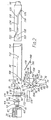
- a pump action shotgun 10 comprising a rear block 12, a barrel 14, a tubular magazine 16 and a trigger device 18.
- the drawing does not show certain well known parts of a shotgun including the stock and aiming sights, the ommission of which will be appreciated by those skilled in the art and the construction of which is conventional.
- the rear housing or block 12 is machined from an aluminium extrusion having a main bore 20 which is closed at one end. The other end of the main bore 20 is open.
- a loading passage 26 is cut through the lower portion of the block and communicates with the magazine 16.
- An eject passage 28 is cut through the block 12 at right angles to the position at which the loading passage 26 is provided and it is aligned therewith.
- a hollow rotary sleeve 30 is rotatably received within the main bore 20.
- An elongated slotted port 34 is formed in the cylindrical wall of the sleeve 30.
- the port 34 is of the same dimensions as the loading passage 26.
- the rear end of the bore 20 threadedly receives and is closed by a cam member 36 having a close ended square section central aperture 38.
- a low cam 40 subtending about 30° at the centre is formed on the front face of the cam member 36 for the reasons that will be set forth below.
- Slidably received within the aperture 38 is a hollow square section boss 42 of a firing pin cam 44 having a central flange 45 on the front face of which are a pair of cams 46 each subtending about 90° at the centre.
- a cylindrical breech 48 closes off the rear of the sleeve 30.
- the breech 48 has a forward portion 50 that fits in the sleeve 30 with an annular space there-around. Behind its central portion 52 the breech has a flange 54 on the rear face of which are a pair of cams 56 that correspond to the cams 46, the cam faces bearing on each other.
- a bore 58 extends through the breech 48 for a firing pin 60.
- the bore 58 has an end throat through which only the reduced diameter front end 64 of the pin 60 can pass.
- the rear end of the firing pin 60 is passes through the firing pin cam 44 and is held by a nut 61.
- a firing spring 65 is received witin the boss 42 and urges the firing pin cam 44 and with it the firing pin 60 forwardly.
- a firing mechanism 66 comprises a triffer 68 and a rocker device 70.
- the trigger 68 is pivotted about a pivot pin 72 that passes through a bore 74 near its upper end.
- the trigger 68 has a shaped finger grip 76 on its lower portion.
- Above the pivot pin 72 there is a cam member 78 having a rounded upper nose 80.
- a shallow cylindrical vertical bore 84 is formed in the projection 82.
- the rocker device 70 is generally "H"-shaped in side view. It is pivotted about a pivot pin 86 that passes through a bore 88 at the junction of the cross-part 90 and the rear vertical part 92.
- the upper portion of the vertical part 92 constitutes a sear 94 that in its operative position lies in the path of movement of the flange 45 of the firing pin cam 44.
- the upper portion of the forward vertical part 96 constitutes a lockup-pin.
- the lower portion of the cross-part 90 is in the form of a cam surface 98 having a recess portion 100 in which the nose 80 is received and an inclined surface 102 running from the recess portion 100.
- An opening 95 in the rocker device 70 is provided to receive a safety pin as will be described.
- a shallow cylindrical vertical bore 104 is formed in the lower portion of the rear vertical part 92.
- a compression spring 106 has its ends received respectively in the bores 84 and 104. The spring 106 biasses the sear 94 upwardly into an operative position to engage the flange 45 firing pin cam 44. It also biasses the trigger 68 forwardly.
- the nose 78 runs along the cam surface 98 causing the rocker member 90 to pivot (counter clockwise in the drawing) about the pivot pin 86, moving the lock-up pin 96 through an opening 108 in the sleeve 30 to engage in an opening 109 in the barrel 14. Further pulling of the trigger 68 causes the sear 94 to drop into an inoperative position out of the path of the flange 54 permitting the firing pin 60 to be thrown forwardly by the firing spring 65.
- a trigger guard is provided. This is described below.
- the sleeve 30 has an opening 110 at its rear end. It further has an external cam 112 and an internal pin 114 axially spaced respectively at its forward end.
- the barrel 14 has a bore 116 therethrough.
- the rear end 118 of the barrel 14 is of enlarged outside diameter, the end portion 119 of the end 118 is of enlarged inner diameter. This end portion 119 fits within the sleeve 30.
- the barrel 14 is movable from a rear position in which it extends to the rear of the sleeve 30 and contains the forward portion 50 of the breech 48 and a forward position (as shown in Figure 1) in which only a portion thereof is within the sleeve 30.
- a groove 120 is cut into the rear end 118 of the barrel 14 and receives therein the internal pin 114 carried by the sleeve 30.
- the groove 120 comprises three straight portions 122, 124 and 126 which are angularly spaced by about 90° and which are joined by equally angled inclined portions 128 and 130.
- the location of the rear straight groove portion 122 is such that when the pin 114 engages therein, the port 34 will register with the loading passage 26.
- the position of intermediate straight groove portion 124 is such that when the pin 114 engages therein, the port 34 will register with the eject passage 28 and the position of the front straight groove portion 126 is such that when the pin 114 engages therein the port 34 will be between the barrel 14 and the block 12.
- the lock-up opening 109 is formed in the end portion 119 of the barrel 14. When the barrel 14 is in its rearmost position, this hole 109 registers with the hole 108 to receive the lock-up pin 96 as described above.
- a pair of generally "U"-shaped guides 132 are provided on the barrel 14 having their arms 134 welded to the barrel 14 and being provided with aligned bores in their bases through which bores, the magazine 16 is received. Thus the barrel 14 is held thereby against rotational movement.
- a hand grip 136 secured to the barrel 14 surrounds and covers the guides 132.
- a stop device is provided to control movement of cartridges out of the magazine.
- This device comprises a loop part 140 having an enlarged upper part 142 in which are pivoted respectively two levers 144 and 145 which are arranged axially spaced one before the other.
- Each lever has an anvil part 146 that is above the loop and an end lip 147 within the loop.
- the anvil parts 146 lie in the path of the cam 112.
- Levers 144 and 145 are arranged so that the front lip 147 is moved to permit a cartridge to pass it whereafter the cartridge engages the rear lip. On release of the rear lip, the cartridge moves below the loading opening while the next cartridge in the magazine engages the former lip to be held thereby in the magazine.
- a lifter flap 148 is provided below the loading passage 28. This will be described below.
- the barrel 14 On the front of the forward portion 50 there is an ejector claw 154 and a pusher pin 156.
- the barrel 14 has a ramp 158 cut out adjacent the opening 109.
- the claw 154 When the barrel 14 is moved into its rear position, the claw 154 is moved outwardly by the ramp 158. As the barrel moves forwardly, the claw 154 runs down the ramp 158 to engage the rim of the cartridge case to hold this against forward movement and thus to draw it out of the bore 116.
- the pusher pin 156 urges the cartridge forwardly so that once the end of the barrel 14 clears the eject passage 28, the cartridge case will be ejected therethrough.
- a safety pin (not shown) is provided which can engage in the opening 95 to prevent the rocker device 70 pivotting. When moved the safety pin permits such pivotting.
- a further safety pin (not shown) is movable by a member on the hand grip of the firearm. When the hand grip is free this further safety pin passes through the opening 110 immobilising the sleeve 30 and with it the barrel 14.
- the trigger guard 160 comprises a flat part 162 and a flat ramp 164 leading therefrom. This shape of the trigger guard serves to guide the cartridges into the magazine. Thus the magazine can be loaded without inverting the firearm.
- the lifting flap 166 is pivotally mounted having a rear projection 168.
- a flap extension 170 lies over the flap 166 and is also spring loaded upwardly.
- a depresser pin 172 is mounted in the block below a third cam member 174 on the rear of the breech 48 and this is arranged to engage a pivotted arm 176 that engages the projection 168.
- the cam member 174 causes the pin depresser pin 172 to rock the arm 176 depressing the projection 168 and thus moving the flap 166 upwardly to lift the cartridge into the sleeve.
- the flap extension 170 is also biassed upwardly so that the cartridge is loaded in an horizontal position.
- a person using the firearm first releases the safety catch. He grips the hand grip thereby releasing the further safety pin.
- the barrel 14 is moved forwardly.
- the pin 114 runs along (a) the front straight portion 126 of the groove 120, and (b) then the inclined portion 132 when it causes the sleeve 20 to rotate into the position in which the port 34 is opposite the eject passage 28.
- the sleeve 30 rotates, the two cams 56 and 46 engage and cause the firing pin cam 44 to move backwardly against the biass of the spring.
- the flange 45 rides over the sear 94 which is then is biassed upwardly to engage in the flange 45 and prevent forward movement of the firing pin cam 44 and the firing pin 60. Further forward movement continues until the pin 114 engages the inclined portion 130 moving the sleeve 30 so that the port 34 is opposite the loading passage 28. At this juncture a cartridge is inserted into the sleeve 30 through the loading passage 26 and the port 34 by the loading flap and is aligned with the bore 116 of the barrel 14.
- the barrel 14 is now moved rearwardly so that the cartridge is homed into the barrel bore 116.
- the pin 114 moves in the opposite direction.
- the cartridge will be fully homed in the bore 116 of the barrel 14 and the sear 94 will still be engaging the flange 45.
- the rear end 118 of the barrel 14 will surround the front portion 50 of the breech 48. Also the port 34 will be between the barrel 14 and the block 12.
- the rocker device 70 pivots as described above, first securing all the parts together by means of the lock-up pin 96 entering the openings 109 and 110. Only then is the sear 94 moved downwardly against the biassing compression spring 106 until the sear 94 is moved out of the path of the flange 45.
- the strong firing spring 65 urges the firing pin cam 44 forwardly under considerable force so that the firing pin 60 strikes the detonator cap causing the cartridge to be fired. It will be seen that at this point the cartridge is wholly within the rear end of the barrel 14 which together with the breech 48 can and does absorb all the explosive forces until the cartridge leaves the barrel. Only after the firing, and the release of the trigger, does the lock-up pin 96 move out of the openings 109 and 110 and the barrel 14 and sleeve 30 are free to be moved forwardly.
- the process is then repeated as desired. It will be appreciated that on commencement of the forward movement of the barrel 14, the ejector claw 154 will act to hold the cartridge case preventing it from moving with the barrel and then the end pusher pin 156 will cause the casing to pivot about the ejector claw and be expelled out of the eject passage.
- the trigger and the rocker member may both be made as steel pressings as is the trigger guard.
- the barrel is made from high tensile steel as is the sleeve.
- Many of the ancilliary parts such as the hand grip and the handle may be plastics mouldings.
- the firing mechanism thus provides a safe and simple mechanism which is easy and inexpensive to manufacture as convenient to operate in practice. It is also particularly strong and unlikely to be destroyed in normal usage.
- the firearm described above has far fewer component parts than conventional shot guns. This permits considerable economies in construction and assembly as well as maintainance. Furthermore it permits the components to be of larger size and thus of greater robustness.
- the moving barrel and sleeve arrangement permits the overall length of the firearm to be considerably reduced as compared to the length of a firearm having a barrel of the same length. This brings with it advantages in reductions of weight and costs of manufacture.
- the firearm may be an automatic weapon.
- the barrel will be free to move forwardly on firing of the cartridge and a return device such as a spring or gas chamber will be provided to return the barrel to its rearward position.
- the invention can be used with any point target weapon which is breech loaded although at present, it is contemplated that the maximum size of weapon would be one firing cartridges of 54 mm diameter.
Priority Applications (1)
| Application Number | Priority Date | Filing Date | Title |
|---|---|---|---|
| AT87900227T ATE67028T1 (de) | 1985-12-23 | 1986-12-22 | Feuerwaffen. |
Applications Claiming Priority (2)
| Application Number | Priority Date | Filing Date | Title |
|---|---|---|---|
| ZA859792 | 1985-12-23 | ||
| ZA859792 | 1985-12-23 |
Publications (2)
| Publication Number | Publication Date |
|---|---|
| EP0280685A1 EP0280685A1 (en) | 1988-09-07 |
| EP0280685B1 true EP0280685B1 (en) | 1991-09-04 |
Family
ID=25578193
Family Applications (1)
| Application Number | Title | Priority Date | Filing Date |
|---|---|---|---|
| EP87900227A Expired - Lifetime EP0280685B1 (en) | 1985-12-23 | 1986-12-22 | Firearms |
Country Status (11)
| Country | Link |
|---|---|
| US (1) | US4897949A (ja) |
| EP (1) | EP0280685B1 (ja) |
| JP (1) | JPH01501891A (ja) |
| AT (1) | ATE67028T1 (ja) |
| BR (1) | BR8607235A (ja) |
| CS (1) | CS274724B2 (ja) |
| DE (1) | DE3681292D1 (ja) |
| FI (1) | FI882960A0 (ja) |
| IL (1) | IL81083A0 (ja) |
| WO (1) | WO1987003952A1 (ja) |
| ZA (1) | ZA869647B (ja) |
Families Citing this family (12)
| Publication number | Priority date | Publication date | Assignee | Title |
|---|---|---|---|---|
| US5235769A (en) * | 1990-11-05 | 1993-08-17 | Stead Heyns W | Pump firearm having a forwardly moving barrel |
| GB2296302A (en) * | 1994-12-22 | 1996-06-26 | Roland Graham Whiteing | A trigger mechanism |
| US5617665A (en) * | 1995-08-02 | 1997-04-08 | Hoenig; George | Rotating breech gun |
| US6481137B2 (en) * | 2000-12-26 | 2002-11-19 | Johann Franz Kornberger | Revolving firearm |
| DE20319451U1 (de) * | 2003-12-15 | 2005-05-04 | Engel, Heinz-Eckhard, Dr. | Schußwaffe |
| ATE393370T1 (de) * | 2004-02-02 | 2008-05-15 | Sat Swiss Arms Technology Ag | Handfeuerwaffe |
| US7743543B2 (en) * | 2005-10-06 | 2010-06-29 | Theodore Karagias | Trigger mechanism and a firearm containing the same |
| US20070079539A1 (en) * | 2005-10-06 | 2007-04-12 | Theodore Karagias | Trigger mechanism and a firearm containing the same |
| US7347021B1 (en) * | 2006-04-11 | 2008-03-25 | Jones C Barry | Firearm action or receiver |
| DE102009057864B4 (de) | 2009-12-11 | 2012-09-20 | German Sport Guns Gmbh | Handfeuerwaffe |
| US9377255B2 (en) | 2014-02-03 | 2016-06-28 | Theodore Karagias | Multi-caliber firearms, bolt mechanisms, bolt lugs, and methods of using the same |
| US11067347B2 (en) | 2018-11-30 | 2021-07-20 | Theodore Karagias | Firearm bolt assembly with a pivoting handle |
Citations (1)
| Publication number | Priority date | Publication date | Assignee | Title |
|---|---|---|---|---|
| US877657A (en) * | 1905-11-06 | 1908-01-28 | Winchester Repeating Arms Co | Gas-operated gun. |
Family Cites Families (11)
| Publication number | Priority date | Publication date | Assignee | Title |
|---|---|---|---|---|
| US398595A (en) * | 1889-02-26 | emmens | ||
| US886211A (en) * | 1908-02-07 | 1908-04-28 | Kumazo Hino | Pistol. |
| US1179880A (en) * | 1913-03-15 | 1916-04-18 | Joseph H Wesson | Magazine-firearm. |
| US2102199A (en) * | 1937-01-26 | 1937-12-14 | James Edward Moses | Gun |
| BE482420A (ja) * | 1947-05-13 | |||
| US2835998A (en) * | 1952-04-22 | 1958-05-27 | Maerk Mikkel | Slidable barrel gun with a combined sear and cocking member |
| US2963810A (en) * | 1958-10-07 | 1960-12-13 | Marlin Firearms Co | Loading means for bolt-action rifles |
| US3680241A (en) * | 1970-05-20 | 1972-08-01 | Olin Corp | Impact ignition shotgun for firing caseless ammunition |
| DE3246205A1 (de) * | 1982-12-14 | 1984-06-14 | Boge Gmbh, 5208 Eitorf | Hydraulisch daempfendes gummilager |
| JPS6155426A (ja) * | 1984-08-24 | 1986-03-19 | Bridgestone Corp | 防振装置 |
| FR2572507B1 (fr) * | 1984-10-30 | 1989-03-24 | Guibert Francois | Fusil automatique perfectionne a canon basculant ou non |
-
1986
- 1986-12-22 DE DE8787900227T patent/DE3681292D1/de not_active Expired - Lifetime
- 1986-12-22 WO PCT/GB1986/000788 patent/WO1987003952A1/en active IP Right Grant
- 1986-12-22 US US07/216,718 patent/US4897949A/en not_active Expired - Fee Related
- 1986-12-22 JP JP87500367A patent/JPH01501891A/ja active Pending
- 1986-12-22 BR BR8607235A patent/BR8607235A/pt unknown
- 1986-12-22 AT AT87900227T patent/ATE67028T1/de not_active IP Right Cessation
- 1986-12-22 EP EP87900227A patent/EP0280685B1/en not_active Expired - Lifetime
- 1986-12-23 CS CS986986A patent/CS274724B2/cs unknown
- 1986-12-23 IL IL81083A patent/IL81083A0/xx unknown
- 1986-12-23 ZA ZA869647A patent/ZA869647B/xx unknown
-
1988
- 1988-06-21 FI FI882960A patent/FI882960A0/fi not_active IP Right Cessation
Patent Citations (1)
| Publication number | Priority date | Publication date | Assignee | Title |
|---|---|---|---|---|
| US877657A (en) * | 1905-11-06 | 1908-01-28 | Winchester Repeating Arms Co | Gas-operated gun. |
Also Published As
| Publication number | Publication date |
|---|---|
| EP0280685A1 (en) | 1988-09-07 |
| WO1987003952A1 (en) | 1987-07-02 |
| ATE67028T1 (de) | 1991-09-15 |
| IL81083A0 (en) | 1987-03-31 |
| US4897949A (en) | 1990-02-06 |
| ZA869647B (en) | 1988-09-28 |
| CS986986A2 (en) | 1990-09-12 |
| CS274724B2 (en) | 1991-10-15 |
| FI882960A (fi) | 1988-06-21 |
| DE3681292D1 (de) | 1991-10-10 |
| BR8607235A (pt) | 1988-11-01 |
| JPH01501891A (ja) | 1989-06-29 |
| FI882960A0 (fi) | 1988-06-21 |
Similar Documents
| Publication | Publication Date | Title |
|---|---|---|
| US6564691B2 (en) | Semi-automatic gas-operated shotgun | |
| CA2334844C (en) | Grenade launcher | |
| US5433134A (en) | Blank firing conversions for semiautomatic pistols | |
| US4058922A (en) | Rifle adapter assembly | |
| US6415702B1 (en) | Double action semi-automatic handgun | |
| US9714804B2 (en) | Firearm with safe axis firing pin and center aligned barrel | |
| US6070512A (en) | Handgun and method of operating handgun | |
| GB2058304A (en) | Automatic fire control means and conversion to single shot | |
| EP0280685B1 (en) | Firearms | |
| US4505183A (en) | Gas actuated operating mechanism for autoloading firearm | |
| US5517896A (en) | Semi-automatic handgun with independent firing spring | |
| US4407085A (en) | Handgun firing mechanism | |
| US4467698A (en) | Angular shape firing pin for use with a collapsible toggle recoil in a hand held weapon | |
| US4646619A (en) | Singulating apparatus for a semiautomatic firearm | |
| KR100429662B1 (ko) | 소화기용탄피방출장치 | |
| US11313635B2 (en) | Lever-coupled device for selectively preventing a firearm from discharging | |
| EP1106955B1 (en) | Firearm having inertia striker mechanism | |
| US20200309474A1 (en) | Semi-automatic rifle restrictors and methods | |
| US3039366A (en) | Target pistol with breech bolt locking mechanism | |
| US5517897A (en) | Semi-automatic handgun with unalterable trigger mechanism | |
| CA1319285C (en) | Firearms | |
| US5727345A (en) | Semiautomatic firearm with gas operated rotating cylinder | |
| US4894939A (en) | Safety for fire arms | |
| AU599394B2 (en) | Firearm | |
| US4899477A (en) | Hand-held automatic firearm |
Legal Events
| Date | Code | Title | Description |
|---|---|---|---|
| PUAI | Public reference made under article 153(3) epc to a published international application that has entered the european phase |
Free format text: ORIGINAL CODE: 0009012 |
|
| 17P | Request for examination filed |
Effective date: 19880620 |
|
| AK | Designated contracting states |
Kind code of ref document: A1 Designated state(s): AT BE CH DE FR GB IT LI LU NL SE |
|
| 17Q | First examination report despatched |
Effective date: 19890426 |
|
| GRAA | (expected) grant |
Free format text: ORIGINAL CODE: 0009210 |
|
| AK | Designated contracting states |
Kind code of ref document: B1 Designated state(s): AT BE CH DE FR GB IT LI LU NL SE |
|
| PG25 | Lapsed in a contracting state [announced via postgrant information from national office to epo] |
Ref country code: LI Effective date: 19910904 Ref country code: CH Effective date: 19910904 |
|
| REF | Corresponds to: |
Ref document number: 67028 Country of ref document: AT Date of ref document: 19910915 Kind code of ref document: T |
|
| REF | Corresponds to: |
Ref document number: 3681292 Country of ref document: DE Date of ref document: 19911010 |
|
| PGFP | Annual fee paid to national office [announced via postgrant information from national office to epo] |
Ref country code: GB Payment date: 19911113 Year of fee payment: 6 |
|
| PGFP | Annual fee paid to national office [announced via postgrant information from national office to epo] |
Ref country code: LU Payment date: 19911129 Year of fee payment: 6 |
|
| ITF | It: translation for a ep patent filed |
Owner name: MODIANO & ASSOCIATI S.R.L. |
|
| REG | Reference to a national code |
Ref country code: CH Ref legal event code: PL |
|
| PGFP | Annual fee paid to national office [announced via postgrant information from national office to epo] |
Ref country code: SE Payment date: 19911216 Year of fee payment: 6 |
|
| PGFP | Annual fee paid to national office [announced via postgrant information from national office to epo] |
Ref country code: FR Payment date: 19911220 Year of fee payment: 6 |
|
| PGFP | Annual fee paid to national office [announced via postgrant information from national office to epo] |
Ref country code: AT Payment date: 19911230 Year of fee payment: 6 |
|
| PGFP | Annual fee paid to national office [announced via postgrant information from national office to epo] |
Ref country code: NL Payment date: 19911231 Year of fee payment: 6 |
|
| ET | Fr: translation filed | ||
| PGFP | Annual fee paid to national office [announced via postgrant information from national office to epo] |
Ref country code: BE Payment date: 19920107 Year of fee payment: 6 |
|
| EPTA | Lu: last paid annual fee | ||
| PLBE | No opposition filed within time limit |
Free format text: ORIGINAL CODE: 0009261 |
|
| STAA | Information on the status of an ep patent application or granted ep patent |
Free format text: STATUS: NO OPPOSITION FILED WITHIN TIME LIMIT |
|
| 26N | No opposition filed | ||
| PG25 | Lapsed in a contracting state [announced via postgrant information from national office to epo] |
Ref country code: LU Free format text: LAPSE BECAUSE OF NON-PAYMENT OF DUE FEES Effective date: 19921222 Ref country code: GB Effective date: 19921222 Ref country code: AT Effective date: 19921222 |
|
| PG25 | Lapsed in a contracting state [announced via postgrant information from national office to epo] |
Ref country code: SE Effective date: 19921223 |
|
| PG25 | Lapsed in a contracting state [announced via postgrant information from national office to epo] |
Ref country code: BE Effective date: 19921231 |
|
| BERE | Be: lapsed |
Owner name: WHITEING ROLAND GRAHAM Effective date: 19921231 |
|
| PG25 | Lapsed in a contracting state [announced via postgrant information from national office to epo] |
Ref country code: NL Effective date: 19930701 |
|
| NLV4 | Nl: lapsed or anulled due to non-payment of the annual fee | ||
| GBPC | Gb: european patent ceased through non-payment of renewal fee |
Effective date: 19921222 |
|
| PG25 | Lapsed in a contracting state [announced via postgrant information from national office to epo] |
Ref country code: FR Effective date: 19930831 |
|
| REG | Reference to a national code |
Ref country code: FR Ref legal event code: ST |
|
| REG | Reference to a national code |
Ref country code: GB Ref legal event code: 728C |
|
| EUG | Se: european patent has lapsed |
Ref document number: 87900227.7 Effective date: 19930709 |
|
| REG | Reference to a national code |
Ref country code: GB Ref legal event code: 728R |
|
| REG | Reference to a national code |
Ref country code: GB Ref legal event code: 728Z |
|
| REG | Reference to a national code |
Ref country code: GB Ref legal event code: 728N |
|
| PGFP | Annual fee paid to national office [announced via postgrant information from national office to epo] |
Ref country code: DE Payment date: 19970901 Year of fee payment: 11 |
|
| PG25 | Lapsed in a contracting state [announced via postgrant information from national office to epo] |
Ref country code: DE Free format text: LAPSE BECAUSE OF NON-PAYMENT OF DUE FEES Effective date: 19980901 |
|
| PG25 | Lapsed in a contracting state [announced via postgrant information from national office to epo] |
Ref country code: IT Free format text: LAPSE BECAUSE OF NON-PAYMENT OF DUE FEES;WARNING: LAPSES OF ITALIAN PATENTS WITH EFFECTIVE DATE BEFORE 2007 MAY HAVE OCCURRED AT ANY TIME BEFORE 2007. THE CORRECT EFFECTIVE DATE MAY BE DIFFERENT FROM THE ONE RECORDED. Effective date: 20051222 |