EP0280657B1 - Flexible abrasives - Google Patents
Flexible abrasives Download PDFInfo
- Publication number
- EP0280657B1 EP0280657B1 EP88810118A EP88810118A EP0280657B1 EP 0280657 B1 EP0280657 B1 EP 0280657B1 EP 88810118 A EP88810118 A EP 88810118A EP 88810118 A EP88810118 A EP 88810118A EP 0280657 B1 EP0280657 B1 EP 0280657B1
- Authority
- EP
- European Patent Office
- Prior art keywords
- metal
- resin
- abrasive
- mask
- metal film
- Prior art date
- Legal status (The legal status is an assumption and is not a legal conclusion. Google has not performed a legal analysis and makes no representation as to the accuracy of the status listed.)
- Expired - Lifetime
Links
Images
Classifications
-
- B—PERFORMING OPERATIONS; TRANSPORTING
- B24—GRINDING; POLISHING
- B24D—TOOLS FOR GRINDING, BUFFING OR SHARPENING
- B24D11/00—Constructional features of flexible abrasive materials; Special features in the manufacture of such materials
- B24D11/04—Zonally-graded surfaces
-
- B—PERFORMING OPERATIONS; TRANSPORTING
- B24—GRINDING; POLISHING
- B24D—TOOLS FOR GRINDING, BUFFING OR SHARPENING
- B24D3/00—Physical features of abrasive bodies, or sheets, e.g. abrasive surfaces of special nature; Abrasive bodies or sheets characterised by their constituents
- B24D3/34—Physical features of abrasive bodies, or sheets, e.g. abrasive surfaces of special nature; Abrasive bodies or sheets characterised by their constituents characterised by additives enhancing special physical properties, e.g. wear resistance, electric conductivity, self-cleaning properties
-
- B—PERFORMING OPERATIONS; TRANSPORTING
- B24—GRINDING; POLISHING
- B24D—TOOLS FOR GRINDING, BUFFING OR SHARPENING
- B24D11/00—Constructional features of flexible abrasive materials; Special features in the manufacture of such materials
-
- B—PERFORMING OPERATIONS; TRANSPORTING
- B24—GRINDING; POLISHING
- B24D—TOOLS FOR GRINDING, BUFFING OR SHARPENING
- B24D11/00—Constructional features of flexible abrasive materials; Special features in the manufacture of such materials
- B24D11/001—Manufacture of flexible abrasive materials
- B24D11/005—Making abrasive webs
-
- B—PERFORMING OPERATIONS; TRANSPORTING
- B24—GRINDING; POLISHING
- B24D—TOOLS FOR GRINDING, BUFFING OR SHARPENING
- B24D11/00—Constructional features of flexible abrasive materials; Special features in the manufacture of such materials
- B24D11/06—Connecting the ends of materials, e.g. for making abrasive belts
-
- B—PERFORMING OPERATIONS; TRANSPORTING
- B24—GRINDING; POLISHING
- B24D—TOOLS FOR GRINDING, BUFFING OR SHARPENING
- B24D18/00—Manufacture of grinding tools or other grinding devices, e.g. wheels, not otherwise provided for
- B24D18/0018—Manufacture of grinding tools or other grinding devices, e.g. wheels, not otherwise provided for by electrolytic deposition
-
- B—PERFORMING OPERATIONS; TRANSPORTING
- B24—GRINDING; POLISHING
- B24D—TOOLS FOR GRINDING, BUFFING OR SHARPENING
- B24D3/00—Physical features of abrasive bodies, or sheets, e.g. abrasive surfaces of special nature; Abrasive bodies or sheets characterised by their constituents
- B24D3/001—Physical features of abrasive bodies, or sheets, e.g. abrasive surfaces of special nature; Abrasive bodies or sheets characterised by their constituents the constituent being used as supporting member
- B24D3/002—Flexible supporting members, e.g. paper, woven, plastic materials
-
- B—PERFORMING OPERATIONS; TRANSPORTING
- B24—GRINDING; POLISHING
- B24D—TOOLS FOR GRINDING, BUFFING OR SHARPENING
- B24D3/00—Physical features of abrasive bodies, or sheets, e.g. abrasive surfaces of special nature; Abrasive bodies or sheets characterised by their constituents
- B24D3/02—Physical features of abrasive bodies, or sheets, e.g. abrasive surfaces of special nature; Abrasive bodies or sheets characterised by their constituents the constituent being used as bonding agent
- B24D3/04—Physical features of abrasive bodies, or sheets, e.g. abrasive surfaces of special nature; Abrasive bodies or sheets characterised by their constituents the constituent being used as bonding agent and being essentially inorganic
- B24D3/06—Physical features of abrasive bodies, or sheets, e.g. abrasive surfaces of special nature; Abrasive bodies or sheets characterised by their constituents the constituent being used as bonding agent and being essentially inorganic metallic or mixture of metals with ceramic materials, e.g. hard metals, "cermets", cements
Description
- This invention relates to flexible abrasive member particularly suitable for abrading, grinding, smoothing, and finishing operations on stone, glass and other materials in heavy-duty applications.
- United States patent no.4,256,467, issued August 17, 1981, to lan Gorsuch discloses a flexible abrasive member comprising a flexible non-conductive mesh carrying a multitude of nickel deposits in which abrasive material, such as diamond grit, is embedded.
- According to the Gorsuch patent, the flexible abrasive member is manufactured by first laying a sheet of flexible nonconductive mesh material onto a smooth electrically conductive surface, suitably masked to expose only those surface portions where electrodeposition is desired, so that the mesh material is in immovable relationship with the conductive surface. Nickel is then electrodeposited onto the exposed portions of the smooth surface through the mesh material in the presence of abrasive material so that the abrasive material becomes embedded in the metal layer and the mesh becomes embedded in the nickel deposits
- Finally, the mesh is stripped from the electrically conductivesurface and cut into the desired shape.
- There are, however, a number of disadvantages associated with the process. The preparation of the cylinder prior to each deposition is expensive and complex. The process is slow and can only operate on a batch basis because a sheet of flexible mesh material of specific size must be attached to the cylinder, applied under tension, and maintained in immovable relationship therewith.
- More importantly, the product produced by the Gorsuch process is structurally weak and only suitable for light-duty operations, such as lens grinding. If the product is used in heavier duty applications, such as abrading belts, the mesh has to be bonded to a suitable substrate. The heat generated during the abrading operation makes it difficult to provide a satisfactory bond, and difficulties have been experienced due to the belts breaking, the nickel deposits chipping off the intrinsically weak mesh, and delamination of the belts.
- Our co-pending Canadian application no. 518,201, filed on September 15. 1986, describes a method which overcones the problems relating to the preparation of the conductive cylinder and permits continuous operation of the process. In this method the mask is applied directly to the mesh, which is rendered conductive, instead of to the conductive surface. When a mesh is employed, however, the abrasive member must still be boned to a strong substrate for heavy-duty applications.
- French patent no. 2,565,870 describes a method of forming an abrasive member wherein a metal layer is fixedly attached to one surface of a thermoplastic sheet, a mask of plating resistant material is applied to the exposed surface of the metal layer, the plating resistant material having a multitude of discrete openings therein, and metal is electrodeposited through said discrete openings onto the metal layer in the presence of particulate abrasive material so that the particulate abrasive material becomes embedded in the metal deposits.
- While such a method represents an improvement over the prior art discussed above, there is a tendency for the metal deposits to chip off the substrate due to the very high shearing forces applied to them.
- According to the present invention the voids between the metal deposits are at least partially filled with resin to reduce lateral movement of the metal deposits.
- The resin fills the interstices between the deposits, reducing the shearing forces applied to them during the abrading process. As a result, the tendency of the deposits to chip off is dramatically reduced.
- The resin is preferably filled with a filler, such as silicon carbide.
- The deposition is preferably carried out by electrodeposition although electroless deposition can be employed. The preferred metal for the film is copper and for the metal deposits nickel, although other combinations can be employed.
- In a preferred embodiment, the mask is stripped from the sheet after electrodeposition of the metal to expose the metal film, and the metal film between the discrete metal electrodeposits is etched sway to expose the sheet prior to filling with resin.
- The mask can be, applied to the metal film by coating with a layer of a photopolymer and exposing the photopolymer to ultra violet light through a screen defining the openings. The coating is then developed, preferably by treatment with an alxali, such as sodium hydroxide. The photopolymer can be a dry film photopolymer such as a dry film photopolymer supplied under the name Riston by Dupont, a laminar dry film resist supplied by Dynachem, or dry film resist supplied by Herculestic, or a liquid film resist supplied by Kodak, GAF, Dynachem, Dupont, or Fuji film. The photopolymer is desirably exposed to ultra-violet light. However, any other type of radiation which degrades the polymer such that it can be developed is suitable.
- Alternatively, the mask may be applied by silk screening, in which case the mask may be made of ultra-violet light curable or thermally curable inks such as infrared heat curable inks. Such curable plating resists and etching resists may be supplied by McDermid Inc., Dynachem and M&T Chemicals.
- The flexible substrate is preferably in the form of a woven fabric, but it may be fibre glass epoxy laminate of the type used for printed circuit board applications, supplied by Westinghouse and GE, when it is desired to make abrasive pads and disks. The sheet nay also be formed of a phenolic resin, such as a phenol formaldehyde resin or it may be a polyester fibre glass laminate also supplied for printed circuit board applications. Such sheets suitably have an overall thickness of about 0.2 to 0.3 mm (8 to 12 mils).
- For forming a flexible abrasive member, a copper clad, fibre free resin system such as that supplied under the trademark Kapton (by Dupont), which is used for flexible printed circuits may be used. However, in a particularly desirable embodiment of the present invention, the sheet is formed of a strong woven fabric on which the metal film is deposited. A particularly suitable fabric is made of polyaramid yarn, such as p-poly (phenylene) terephthalamide yarn, which is supplied under the trademark Kevlar.
- The metal film is fixedly attached to the surface of the sheet and is laminated as a film or deposited by electroless plating, vapour deposition, sputtering or electrochemical deposition, such as electroplating. The metal may be any electrically conductive metal such as copper, aluminium, nickel, steel, rhodium or gold, but is preferably copper. Suitably the metal film has a thickness from 0.004 to 0.356 mm (3/20 to 14 thousandths of an inch) preferably 0.012 to 0.07 mm (7/10 to 2.8 thousandths of an inch).
- The abrasive material is a conventional particulate abrasive such as diamond grit or cubic boron nitride, and preferably industrial diamond. The metal can be any metal which can be deposited from a suitable bath by electrodeposition or electroless deposition and is preferably nickel or copper, more preferably nickel.
- In a preferred embodiment, the sheet with the metal film attached thereto is continuously passed through an electrolytic bath to form a cathode, the anodes of which are formed by the metal, whereby the metal is continuously deposited in the discrete openings and during said electrodeposition the particulate abrasive is released into the bath. In order to ensure that the sheet is present in the bath as a cathode, it is connected to a source of negative potential. The sheet is preferably in contact with a smooth non- conductive surface such as a plastic surface, in the bath, which is suitably a nickel sulphamate bath. The mask, which is in the form of a very thin sheet a few thousandths, e.g. 0.08 to 0.1 mm (3 to 4 thousandths of an inch) thick, defines a lattice with a large number of openings, for example 1.5 mm (1/16 of an inch) in diameter.
- After removal from the bath, the sheet is stripped and etched with alkaline solution. A further very significant feature of the invention is that the KevlarTM sheet bearing the diamond-embedded nickel deposits is coated with a resin, such as a two-part polyurethane resin sold under the trade designation UR 2139X-1 and UR 2139X-LA by Elecbro Inc. After stripping and etching, the Kevlar sheet consists of a multitude of nickel nodules carried by copper segments bonded to the Kevlar fabric.
- The nodules hold quite well onto the fabric during use, but their tendency to chip off can be dramatically seduced by coating with polyurethane resin. This fills the interstices between the nodules, thereby reducing the shearing forces as the fabric is moved over the working surface. It has been further found that the use of a filled resin, i.e. a resin filled with a solid particulate material, particularly silicon carbide powder further inhibits the lateral movement of the nodules reducing even further their tendencies to chip off.
- In a still further feature of the invention, the nickel nodules are given predetermined characteristic shapes. In one embodiment, the nodules have a crescent-moon shape. This has the effect of minimizing the use of diamond without impairing the abrasive properties. The removal of abraded material can also be assisted by careful design of the shapes of the nodules. The photographic and silk-screen processes described above lend themselves particularly well to the fabrication of shaped nodules.
- The invention will now be described in more details, by way of example, only, with reference to the accompanying drawings, in which :
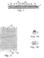
- Figure 1 shows in cross-section a short length of Kevlar fabric carrying diamond-bearing nickel deposits;
- Figure 2 shows a laminated substrate bearing a surface mask defining a regular pattern of crescent-shaped holes;
- Figure 3a shows a detail of one of the shaped holes; and
- Figure 3b shows a detail of a group of holes.
- A copper clad, fibre glass epoxy laminate, sold for printed circuit board applications by Westinghouse or GE, having a thickness of 0.2 to 0.3 mm (8 mils to 12 mils) had its copper surface mechanically cleaned with a scrubber. A dry film photopolymer supplied by Dynachem was laminated to the copper surface at about 104.5 ° C and then exposed to ultra violet light through an apertured screen defining the holes with a Scannex exposure unit. The protective Mylar sheet, which comes with the dry film, was removed and the exposed film developed with potassium hydroxide solution.
- The product bearing the photographically formed mask was then treated in a commercial electrolytic nickel sulphamate bath, supplied under the trademark SNR 24 by Hansen, operating at 170 amps and 9 volts DC at a temperature of 140 ° C.
- The flexible abrasive member leaving the bath, though suitable for cutting and use without further treatment, was treated with a Chemalex stripper to strip off the dry photofilm and then etched with alkaline- based copper etching solution supplied by Hunt Chemicals, by spray etching.
- The abrasive member had a clear translucent aesthetically pleasing appearance with well defined protuberances containing the diamond abrasive and substantially no intermediate diamond-containing metal between the protuberances. This is in contrast to the product obtained according to the process described in our copending Canadian application N 518,210, which displayed a more untidy appearance and tended to have metal and diamond particles present between the protuberances. The clean appearance of the abrasive member has consumer appeal, particularly in the do-it-yourself market, but it also provides a more efficient abrading member. In addition it makes the product cheaper to manufacture as there is less waste of metal and abrasive material.
- The presence of the copper layer has a number of advantages : It provides a smooth surface on which deposition can take place, which is important to prevent break-through of the mask and to permit even distribution of diamond grit. When the mask and copper bridging regions between the nodules are removed, the remaining copper segments under the nodules, by which the nodules are attached to the substrate, form part of the protuberances. To achieve a protuberance a given height, the electrodeposition time can be shortened due to the presence of the underlying metal segments. The metal deposits should stand proud of the substrate by an amount sufficient to permit adequate removal of abraded material and avoid undue wear.
- A 28.5 g (10 ounce) Kevlar fabric 61 x 61 cm (24 x 24 inches) in size was subjected to electroless copper plating by passing through the standard electroless copper plating process known under the trademark Ethone System CU 701. Such a process is conventionally used for producing printed circuit boards with a copper coating of a thickness of 80 to 120 microns deposited on both sides.
- The copper coated fabric was then subjected to masking and nickel and diamond deposition by the method described in example 1. The copper clad sheets can be treated in a manner similar to the fibre glass epoxy laminate.
- Upon removal from the electrolytic bath, and after stripping and etching, the Kevlar sheets were coated with polyurethane resin to fill the interstices between the nickel nodules. The sheets were then cut and formed into belts after the reverse surface was covered with a rubberized epoxy resin system to prevent fraying and cutting of the belt.
- A sheet of Barrday F-2160/175 Kevlar 29-165tex (1500 denier) scoured fabric was impregnated with B0800 LOMODTM copolyester elastomeric resin. The resin was in liquid form and applied with rollers. A layer of 28.5 g (10 oz.) copper foil was then applied to the impregnated sheet and the assembly maintained in a press under 1,73 x 10⁻⁸ Ncm-2 (1.73 x 10⁻³ dyne cm-2) (250 psi) pressure for approximately one hour at room temperature.
- Upon removal from the press, the exposed surface of the foil was mechanically scuffed to improve adhesion. A plating-resistant mask with a multitude of openings was then applied to the copper foil in the manner described above, and the laminate placed in an electrolytic deposition bath. Nickel was deposited onto the copper foil through the openings in the mask with diamond particles sprinkled into the tank during the electrodeposition.
- The mask was stripped from the foil and the intervening copper etched away to leave upstanding diamond-bearing nickel deposits lying on small copper discs. The interstices between the nickel deposits were then filled with a flexible polyurethane resin, such as Elecbro UR 2139X-1 and UR 2139X-1A, so that the abrasive product presented a continuous surface on the abrasive side. As discussed above, the use of a resin coating has the important advantage that during use the tendency of the deposits to be chipped off the backing fabric is minimized. Other flexible resins can be employed.
- The LOMOD TM resin substantially enhances the properties of the fabric. It prevents degradation of the fabric due to fraying and scuffing during heavy industrial use without impairing the flexibility of the belt. It has good physical, mechanical, thermal, electrical and flame-resistant properties.
- Of equal significance is the fact that the LOMODTM has sufficient strength to permit lamination of the copper foil to the fabric and good retention of the residual copper segments after stripping and etching during use.
- The advantage of this technique is that unlike the copper spray, the laminated foil has a smooth surface. The uniformity of the abrasive can be accurately controlled and the tendency of the electrolytic deposits to break through the masked portions minimized.
- The physical data for these LOMOD TM resins are as follows:

- Belts, discs and other types of abrasive product made with LOMODTM impregnated sheets in the manner described have exceptional strength and abrasive properties.
- A sheet of 28.5g (10 ounce) KevlarTM (a trademark of Dupont for p-poly-(phenylene) terephthalamide yarn) 61 x 61 cm (24 x 24 inch) fabric was bonded under heat pressure with LOMODTM (available from General Electric) resin to a copper sheet having a surface density of one ounce per square foot. The surface of the copper sheet was cleaned and scrubbed with an abrasive brush in a scrubbing machine.
- The cleaned laminate was passed through a dry film laminator made by Thiokol/Dynachem company (Model 30) to apply a Riston (a trademark of Dupont) photo-resist film (an alternative is Dynachem film).
- Laminate with the applied photo-resist film was placed in a Scannex II exposure unit with a screen defining the desired pattern of crescent-shaped holes. The screen can be produced photographically.
- After exposure to ultra violet light, the image was developed and the protective Mylar film, applied by the laminator, removed.
- The electrodeposition took place in the presence of diamond grit in an electrolytic bath in a similar manner to that described above to form crescent-shaped diamond-embedded nickel pellets. Other abrasive particulate material, such as cubic boron nitride, can be employed,
- After electrodeposition, the mask and exposed copper were removed with an alkaline stripping and etching solution.
- The product was then roller coated with polyurethane protective resin, having the trade designation UR 2139X-1 and UR 2139X-1A by Elecbro Inc, to fill the interstices between the nickel deposits.
- The sheet was then cut into strips and the strips formed into belts ready for use as an abrasive.
- Instead of using photo-resist materials to form the mask, the mask can be applied by a silk screening process. In this case, the mask is made of enplate UR 2311B silk screening material which is ultra-violet cured after application in the silk-screening process.
- Referring to Figure 1, a length of Kevlar fabric 1 is impregnated with Lomod Tm and has bonded thereto copper discs 2. These discs were applied as a copper foil in the manner described above but are all that remain of the original foil after the stripping and etching operation described above.
- The
nickel nodules 3 are electrolytically deposited on the copper discs 1 and havediamond particles 4 embedded therein. - The voids between the
nodules 3 are filled with polyurethane resin 5 in the manner described above. The resin 5 reduces lateral movement of thenodules 4 and has a profound effect on their tendency to chip off during the abrasion process. The resin has a greater effect than would result merely from its adhesive action due to the way in which it stabilizes the nodules in operation. One of the factors inhibiting widespread use of this type of abrasive product in the past has been the difficulty of retaining the nodules on the substrate in the hostile environment of an industrial abrading machine. - The sheets are cut into strips and formed into belts by making a butt joint and applying a tape on the rear side with Bostik 707OTm adhesive. To minimize wear, the rear side should be slightly scuffed in the region where the tape is to be located so as to avoid a noticeable bump when the tape is in place. The edges should desirably be cut in a wavy line to reduce lateral movement.
- The laminate 11, shown in figure 2, comprises a Kevlar TM fabric resin bonded to a copper sheet 12 covered with a
surface mask 13 of photo-resist material defining crescent-shapedholes 14 through which electrodeposition occurs. The laminate shown in Figure 2 is subsequently placed in an electrolytic tank to permit deposition of nickel in the presence of diamond grit through the shaped holes 14. This process produces crescent-shaped pellets at the locations of the holes with diamond grit embedded in the nickel. - After removal from the tank, the mask and exposed copper are striped from the Kevlar TM to leave a sheet consisting of a regular pattern of crescent-shaped pellets firmly attached to the Kevlar TM backing. Each pellet consists of an electrodeposit of nickel bearing the diamond grit carried on a crescent-shaped segment of copper bonded to the underlying fabric.
- Figure 3a shows in detail the shape of the holes. The crescent-shapes are defined by overlapping circles of slightly different radii. Figure 3b shows how the holes are arranged in a symmetrical arrangement.
- The manufactured sheet is subsequently cut into strips, which in turn are formed into belts. The crescent-shaped modules make the belts unidirectional, in that the convex edge has to face the direction of movement a of the belt. This is generally a significant disadvantage.
- The use of crescent-shapes permits significant savings in diamond grit, since the surface area of the pellets is less than for circular pellets, without deterioration in the abrasive properties, and furthermore the removal of abraded matter is improved.
- The holes can have other shapes. For example, honeycomb shapes provide the belt with greater rigidity.
- The spacing and size of the pellets can be varied to fine tune the properties of the abrasive product according to the intended application. A much greater degree of control can be exercised over the abrasive properties than was previously possible. For rough grinding purposes, the pellets are spaced further apart and larger diamonds employed. For smooth grinding applications, the pellets are brought closer together and smaller diamonds used.
- Kevlar TM is a particularly useful material for making abrasive belts. For disks on the other hand, the copper foil can be bonded onto fiberglass or other semi-rigid material and the fiberglass then laminated onto a firm backing, for example a polyester backing.
Claims (20)
Priority Applications (1)
| Application Number | Priority Date | Filing Date | Title |
|---|---|---|---|
| AT88810118T ATE93438T1 (en) | 1987-02-27 | 1988-02-26 | FLEXIBLE ABRASIVES. |
Applications Claiming Priority (10)
| Application Number | Priority Date | Filing Date | Title |
|---|---|---|---|
| CA530811 | 1987-02-27 | ||
| CA530811 | 1987-02-27 | ||
| CA531996 | 1987-03-13 | ||
| CA000531996A CA1280897C (en) | 1987-03-13 | 1987-03-13 | Abrasive member with deposits carrying particles |
| CA549901 | 1987-10-21 | ||
| CA000549901A CA1298472C (en) | 1987-10-21 | 1987-10-21 | Abrasive member with metal deposits carrying particles |
| CA000552387A CA1302097C (en) | 1987-11-20 | 1987-11-20 | Method of making an abrasive product |
| CA552387 | 1987-11-20 | ||
| CA000556049A CA1317466C (en) | 1988-01-07 | 1988-01-07 | Abrasive product and method |
| CA556049 | 1988-01-07 |
Publications (4)
| Publication Number | Publication Date |
|---|---|
| EP0280657A2 EP0280657A2 (en) | 1988-08-31 |
| EP0280657A3 EP0280657A3 (en) | 1990-10-31 |
| EP0280657B1 true EP0280657B1 (en) | 1993-08-25 |
| EP0280657B2 EP0280657B2 (en) | 2003-05-07 |
Family
ID=27508257
Family Applications (1)
| Application Number | Title | Priority Date | Filing Date |
|---|---|---|---|
| EP88810118A Expired - Lifetime EP0280657B2 (en) | 1987-02-27 | 1988-02-26 | Flexible abrasives |
Country Status (10)
| Country | Link |
|---|---|
| US (2) | US4874478A (en) |
| EP (1) | EP0280657B2 (en) |
| JP (1) | JPS6458480A (en) |
| KR (1) | KR880009734A (en) |
| AU (2) | AU1215788A (en) |
| BR (1) | BR8800891A (en) |
| DE (1) | DE3883403T3 (en) |
| DK (1) | DK99288A (en) |
| FI (1) | FI880894A (en) |
| NO (1) | NO880876L (en) |
Cited By (13)
| Publication number | Priority date | Publication date | Assignee | Title |
|---|---|---|---|---|
| US8252263B2 (en) | 2008-04-14 | 2012-08-28 | Chien-Min Sung | Device and method for growing diamond in a liquid phase |
| US8393934B2 (en) | 2006-11-16 | 2013-03-12 | Chien-Min Sung | CMP pad dressers with hybridized abrasive surface and related methods |
| US8398466B2 (en) | 2006-11-16 | 2013-03-19 | Chien-Min Sung | CMP pad conditioners with mosaic abrasive segments and associated methods |
| US8622787B2 (en) | 2006-11-16 | 2014-01-07 | Chien-Min Sung | CMP pad dressers with hybridized abrasive surface and related methods |
| US8777699B2 (en) | 2010-09-21 | 2014-07-15 | Ritedia Corporation | Superabrasive tools having substantially leveled particle tips and associated methods |
| US8974270B2 (en) | 2011-05-23 | 2015-03-10 | Chien-Min Sung | CMP pad dresser having leveled tips and associated methods |
| US9138862B2 (en) | 2011-05-23 | 2015-09-22 | Chien-Min Sung | CMP pad dresser having leveled tips and associated methods |
| US9199357B2 (en) | 1997-04-04 | 2015-12-01 | Chien-Min Sung | Brazed diamond tools and methods for making the same |
| US9221154B2 (en) | 1997-04-04 | 2015-12-29 | Chien-Min Sung | Diamond tools and methods for making the same |
| US9238207B2 (en) | 1997-04-04 | 2016-01-19 | Chien-Min Sung | Brazed diamond tools and methods for making the same |
| US9409280B2 (en) | 1997-04-04 | 2016-08-09 | Chien-Min Sung | Brazed diamond tools and methods for making the same |
| US9463552B2 (en) | 1997-04-04 | 2016-10-11 | Chien-Min Sung | Superbrasvie tools containing uniformly leveled superabrasive particles and associated methods |
| US9475169B2 (en) | 2009-09-29 | 2016-10-25 | Chien-Min Sung | System for evaluating and/or improving performance of a CMP pad dresser |
Families Citing this family (41)
| Publication number | Priority date | Publication date | Assignee | Title |
|---|---|---|---|---|
| DE3912681A1 (en) * | 1989-04-18 | 1990-10-25 | Winter & Sohn Ernst | METHOD FOR GALVANIC COATING OF SEGMENT SURFACES ARRANGED ON THE SURFACE OF A BASIC BODY AND PRODUCTS PRODUCED AFTER THAT |
| DE4106005A1 (en) * | 1991-02-26 | 1992-08-27 | Winter & Sohn Ernst | GRINDING OR CUTTING TOOL AND METHOD FOR THE PRODUCTION THEREOF |
| US5251802A (en) * | 1991-04-25 | 1993-10-12 | Minnesota Mining And Manufacturing Company | Abrasive article and processes for producing it |
| US5127197A (en) * | 1991-04-25 | 1992-07-07 | Brukvoort Wesley J | Abrasive article and processes for producing it |
| US5380390B1 (en) * | 1991-06-10 | 1996-10-01 | Ultimate Abras Systems Inc | Patterned abrasive material and method |
| GB2263911B (en) * | 1991-12-10 | 1995-11-08 | Minnesota Mining & Mfg | Tool comprising abrasives in an electrodeposited metal binder dispersed in a binder matrix |
| US5383512A (en) * | 1993-01-27 | 1995-01-24 | Midwest Research Institute | Method for fabricating a substrate having spaced apart microcapillaries thereon |
| NL9300661A (en) * | 1993-04-19 | 1994-11-16 | K G S Diamind Holding B V | Abrasive article comprising a nonwoven fiber material and a method of manufacturing such an abrasive article. |
| US5354364A (en) * | 1993-06-23 | 1994-10-11 | The Babcock & Wilcox Company | High efficiency advanced dry scrubber |
| US5643344A (en) * | 1995-02-14 | 1997-07-01 | The Babcock & Wilcox Company | Dry scrubber with forced recirculation |
| WO1998028108A1 (en) * | 1996-12-20 | 1998-07-02 | Unique Technology International Private Limited | Manufacture of porous polishing pad |
| EP0984846B1 (en) * | 1997-01-13 | 2004-11-24 | Rodel, Inc. | Method of manufacturing a polymeric polishing pad having photolithographically induced surface pattern |
| ES2176672T3 (en) * | 1997-02-18 | 2002-12-01 | Sandro Giovanni Gius Ferronato | PROCEDURE TO FORM HIGH PRECISION FLEXIBLE ABRASIVE MEMBER |
| US7323049B2 (en) | 1997-04-04 | 2008-01-29 | Chien-Min Sung | High pressure superabrasive particle synthesis |
| US9868100B2 (en) | 1997-04-04 | 2018-01-16 | Chien-Min Sung | Brazed diamond tools and methods for making the same |
| US5976001A (en) * | 1997-04-24 | 1999-11-02 | Diamond Machining Technology, Inc. | Interrupted cut abrasive tool |
| US5919084A (en) * | 1997-06-25 | 1999-07-06 | Diamond Machining Technology, Inc. | Two-sided abrasive tool and method of assembling same |
| DE19727104C2 (en) | 1997-06-26 | 2000-07-20 | Ver Schmirgel & Maschf | Flexible grinding wheel and process for its manufacture |
| US6402603B1 (en) | 1998-12-15 | 2002-06-11 | Diamond Machining Technology, Inc. | Two-sided abrasive tool |
| US6528141B1 (en) | 1998-12-15 | 2003-03-04 | Diamond Machining Technology, Inc. | Support structure and method of assembling same |
| US6261167B1 (en) | 1998-12-15 | 2001-07-17 | Diamond Machining Technology, Inc. | Two-sided abrasive tool and method of assembling same |
| US6096107A (en) * | 2000-01-03 | 2000-08-01 | Norton Company | Superabrasive products |
| EP1331064B1 (en) * | 2002-01-25 | 2009-12-23 | WENDT GmbH | Method to manufacture a grinding tool with galvanically bonded abrasive bodies |
| ITMI20021013A1 (en) * | 2002-05-13 | 2003-11-13 | Kunzle & Tasin S R L | SANDING METHOD OF STONE MATERIALS |
| SI1877219T1 (en) * | 2005-03-15 | 2012-02-29 | Htc Sweden Ab | Method for maintaining a hard, smooth floor surface comprising a polymer material |
| US10065283B2 (en) * | 2005-03-15 | 2018-09-04 | Twister Cleaning Technology Ab | Method and tool for maintenance of hard surfaces, and a method for manufacturing such a tool |
| US9724802B2 (en) | 2005-05-16 | 2017-08-08 | Chien-Min Sung | CMP pad dressers having leveled tips and associated methods |
| US20070149001A1 (en) * | 2005-12-22 | 2007-06-28 | Uka Harshad K | Flexible circuit |
| KR100868658B1 (en) * | 2007-05-18 | 2008-11-12 | 조희철 | Method for fabricating polishing tool |
| KR101121254B1 (en) * | 2011-04-05 | 2012-03-22 | 이화다이아몬드공업 주식회사 | Method for manufacturing electrodeposited diamond wire saw using patterning non-conduction materials |
| EP4000807A1 (en) | 2012-09-05 | 2022-05-25 | Mirka Oy | Flexible grinding product with flattened surface and method for manufacturing the same |
| US20140134933A1 (en) | 2012-11-09 | 2014-05-15 | Di-Coat Corporation | Abrading tools and methods of making same |
| CA3102523C (en) * | 2015-09-24 | 2023-12-12 | Husqvarna Ab | Polishing or grinding pad assembly |
| USD854902S1 (en) | 2016-09-23 | 2019-07-30 | Husqvarna Construction Products North America, Inc. | Polishing or grinding pad |
| USD927952S1 (en) | 2017-08-30 | 2021-08-17 | Husqvarna Ab | Polishing or grinding pad assembly with abrasive disk, spacer, reinforcement and pad |
| AU201810919S (en) | 2017-08-30 | 2018-04-13 | Husqvarna Construction Products North America | Polishing or grinding pad assembly with abrasive discs reinforcement and pad |
| USD958626S1 (en) | 2017-08-30 | 2022-07-26 | Husqvarna Ab | Polishing or grinding pad assembly with abrasive disks, reinforcement and pad |
| US10710214B2 (en) | 2018-01-11 | 2020-07-14 | Husqvarna Ab | Polishing or grinding pad with multilayer reinforcement |
| CN109571302B (en) * | 2018-11-21 | 2021-08-03 | 华侨大学 | Characterization method of semi-fixed abrasive polishing tool interface bonding strength based on tensile strength |
| CN114016091B (en) * | 2020-09-25 | 2022-11-15 | 嘉兴匠鑫医疗科技有限公司 | Method for producing a drive shaft for an insertion-type rotational grinding device |
| CN112171533A (en) * | 2020-10-22 | 2021-01-05 | 郑州瑞特金刚石砂带有限公司 | Superhard material abrasive belt with grinding and polishing effects simultaneously, and preparation method and application thereof |
Family Cites Families (15)
| Publication number | Priority date | Publication date | Assignee | Title |
|---|---|---|---|---|
| US2858256A (en) * | 1953-10-26 | 1958-10-28 | Vitro Corp Of America | Electrophoretic method of making an abrasive article and article made thereby |
| BE530127A (en) * | 1953-11-25 | |||
| US4038047A (en) * | 1969-04-14 | 1977-07-26 | Norton Company | Method of making a flexible resilient abrasive |
| GB1375571A (en) * | 1971-07-27 | 1974-11-27 | ||
| GB1458236A (en) * | 1974-06-14 | 1976-12-08 | Prowse Co Ltd D H | Abrasive tools |
| US4047902A (en) * | 1975-04-01 | 1977-09-13 | Wiand Richard K | Metal-plated abrasive product and method of manufacturing the product |
| US4128972A (en) * | 1975-04-14 | 1978-12-12 | The Osborn Manufacturing Corporation | Flexible polishing wheel and method for producing same |
| US4084941A (en) * | 1976-03-31 | 1978-04-18 | Norton Company | Non-polluting waterproof cloth finish for abrasive cloth |
| GB1498689A (en) * | 1976-08-31 | 1978-01-25 | Kendia Ltd | Cutting disc |
| US4078906A (en) * | 1976-09-29 | 1978-03-14 | Elgin Diamond Products Co., Inc. | Method for making an abrading tool with discontinuous diamond abrading surfaces |
| DE2802027A1 (en) * | 1978-01-18 | 1979-07-19 | Elgin Diamond Prod | Abrading tool with discontinuous diamond pattern - obtd. by electro-nickel bonding diamond particles to surface having interspersed metal and resist zones |
| EP0013486B1 (en) * | 1978-12-12 | 1983-08-03 | Interface Developments Limited | Flexible abrasive member and method of making same |
| JPS58171263A (en) * | 1982-03-30 | 1983-10-07 | Komatsu Ltd | Manufacture of grind stone |
| FR2565870B1 (en) * | 1984-06-15 | 1988-05-13 | Triefus France Applic Indles | METHOD FOR MANUFACTURING DIAMOND TOOLS ON FLEXIBLE SUPPORT AND TOOLS THEREFROM |
| US4826508A (en) * | 1986-09-15 | 1989-05-02 | Diabrasive International, Ltd. | Flexible abrasive coated article and method of making it |
-
1988
- 1988-02-24 AU AU12157/88A patent/AU1215788A/en not_active Abandoned
- 1988-02-25 DK DK099288A patent/DK99288A/en not_active Application Discontinuation
- 1988-02-25 FI FI880894A patent/FI880894A/en not_active IP Right Cessation
- 1988-02-26 BR BR888800891A patent/BR8800891A/en unknown
- 1988-02-26 AU AU12356/88A patent/AU613895B2/en not_active Ceased
- 1988-02-26 EP EP88810118A patent/EP0280657B2/en not_active Expired - Lifetime
- 1988-02-26 DE DE3883403T patent/DE3883403T3/en not_active Expired - Fee Related
- 1988-02-26 JP JP63044072A patent/JPS6458480A/en active Pending
- 1988-02-27 KR KR1019880002114A patent/KR880009734A/en not_active Application Discontinuation
- 1988-02-29 US US07/161,940 patent/US4874478A/en not_active Expired - Lifetime
- 1988-02-29 NO NO880876A patent/NO880876L/en unknown
-
1989
- 1989-08-25 US US07/398,335 patent/US5066312A/en not_active Expired - Lifetime
Cited By (14)
| Publication number | Priority date | Publication date | Assignee | Title |
|---|---|---|---|---|
| US9199357B2 (en) | 1997-04-04 | 2015-12-01 | Chien-Min Sung | Brazed diamond tools and methods for making the same |
| US9463552B2 (en) | 1997-04-04 | 2016-10-11 | Chien-Min Sung | Superbrasvie tools containing uniformly leveled superabrasive particles and associated methods |
| US9409280B2 (en) | 1997-04-04 | 2016-08-09 | Chien-Min Sung | Brazed diamond tools and methods for making the same |
| US9238207B2 (en) | 1997-04-04 | 2016-01-19 | Chien-Min Sung | Brazed diamond tools and methods for making the same |
| US9221154B2 (en) | 1997-04-04 | 2015-12-29 | Chien-Min Sung | Diamond tools and methods for making the same |
| US9067301B2 (en) | 2005-05-16 | 2015-06-30 | Chien-Min Sung | CMP pad dressers with hybridized abrasive surface and related methods |
| US8622787B2 (en) | 2006-11-16 | 2014-01-07 | Chien-Min Sung | CMP pad dressers with hybridized abrasive surface and related methods |
| US8398466B2 (en) | 2006-11-16 | 2013-03-19 | Chien-Min Sung | CMP pad conditioners with mosaic abrasive segments and associated methods |
| US8393934B2 (en) | 2006-11-16 | 2013-03-12 | Chien-Min Sung | CMP pad dressers with hybridized abrasive surface and related methods |
| US8252263B2 (en) | 2008-04-14 | 2012-08-28 | Chien-Min Sung | Device and method for growing diamond in a liquid phase |
| US9475169B2 (en) | 2009-09-29 | 2016-10-25 | Chien-Min Sung | System for evaluating and/or improving performance of a CMP pad dresser |
| US8777699B2 (en) | 2010-09-21 | 2014-07-15 | Ritedia Corporation | Superabrasive tools having substantially leveled particle tips and associated methods |
| US9138862B2 (en) | 2011-05-23 | 2015-09-22 | Chien-Min Sung | CMP pad dresser having leveled tips and associated methods |
| US8974270B2 (en) | 2011-05-23 | 2015-03-10 | Chien-Min Sung | CMP pad dresser having leveled tips and associated methods |
Also Published As
| Publication number | Publication date |
|---|---|
| NO880876D0 (en) | 1988-02-29 |
| DE3883403D1 (en) | 1993-09-30 |
| AU613895B2 (en) | 1991-08-15 |
| DE3883403T3 (en) | 2004-01-08 |
| NO880876L (en) | 1988-08-29 |
| FI880894A (en) | 1988-08-28 |
| FI880894A0 (en) | 1988-02-25 |
| KR880009734A (en) | 1988-10-04 |
| EP0280657B2 (en) | 2003-05-07 |
| EP0280657A2 (en) | 1988-08-31 |
| US4874478A (en) | 1989-10-17 |
| JPS6458480A (en) | 1989-03-06 |
| BR8800891A (en) | 1988-10-04 |
| AU1215788A (en) | 1988-09-01 |
| DK99288D0 (en) | 1988-02-25 |
| US5066312A (en) | 1991-11-19 |
| AU1235688A (en) | 1988-09-01 |
| EP0280657A3 (en) | 1990-10-31 |
| DE3883403T2 (en) | 1994-03-17 |
| DK99288A (en) | 1988-08-28 |
Similar Documents
| Publication | Publication Date | Title |
|---|---|---|
| EP0280657B1 (en) | Flexible abrasives | |
| US6106382A (en) | Abrasive product for dressing | |
| US4826508A (en) | Flexible abrasive coated article and method of making it | |
| US3334041A (en) | Coated abrasives | |
| EP0732175B1 (en) | Abrasive product and method for making | |
| EP0013486B1 (en) | Flexible abrasive member and method of making same | |
| US20050255801A1 (en) | Abrasive material and method of forming same | |
| US5389119A (en) | Abrasive member comprising a nonwoven fabric and a method for making same | |
| GB2287422A (en) | Conditioning by abrading of polishing cloth for semiconductor devices | |
| CA2566888A1 (en) | Abrasive material and method of forming same | |
| EP0263785B1 (en) | A flexible abrasive coated article and method of making it | |
| GB2149417A (en) | Method of making grinding stones | |
| US3543362A (en) | Abrading device or file | |
| JPS6150773A (en) | Diamond endless belt | |
| CA1280897C (en) | Abrasive member with deposits carrying particles | |
| EP0980307A1 (en) | Abrasive material and method of forming same | |
| CA1317466C (en) | Abrasive product and method | |
| CA1049790A (en) | Abrasive tools | |
| GB2223966A (en) | Making flexible abrasive member | |
| CA1298472C (en) | Abrasive member with metal deposits carrying particles | |
| CA1280896C (en) | Flexible abrasive coated article and method of making it | |
| CN88101108A (en) | Flexible abrasives | |
| JPS63139673A (en) | Manufacture of polishing sheet | |
| CA1302097C (en) | Method of making an abrasive product | |
| JP2978240B2 (en) | Gravure printing plate |
Legal Events
| Date | Code | Title | Description |
|---|---|---|---|
| PUAI | Public reference made under article 153(3) epc to a published international application that has entered the european phase |
Free format text: ORIGINAL CODE: 0009012 |
|
| AK | Designated contracting states |
Kind code of ref document: A2 Designated state(s): AT BE CH DE ES FR GB GR IT LI LU NL SE |
|
| PUAL | Search report despatched |
Free format text: ORIGINAL CODE: 0009013 |
|
| AK | Designated contracting states |
Kind code of ref document: A3 Designated state(s): AT BE CH DE ES FR GB GR IT LI LU NL SE |
|
| 17P | Request for examination filed |
Effective date: 19901222 |
|
| RAP1 | Party data changed (applicant data changed or rights of an application transferred) |
Owner name: ABRASIVE TECHNOLOGY N.A., INC. |
|
| 17Q | First examination report despatched |
Effective date: 19820128 |
|
| GRAA | (expected) grant |
Free format text: ORIGINAL CODE: 0009210 |
|
| AK | Designated contracting states |
Kind code of ref document: B1 Designated state(s): AT BE CH DE ES FR GB GR IT LI LU NL SE |
|
| PG25 | Lapsed in a contracting state [announced via postgrant information from national office to epo] |
Ref country code: BE Effective date: 19930825 Ref country code: NL Effective date: 19930825 Ref country code: GR Free format text: LAPSE BECAUSE OF FAILURE TO SUBMIT A TRANSLATION OF THE DESCRIPTION OR TO PAY THE FEE WITHIN THE PRESCRIBED TIME-LIMIT Effective date: 19930825 Ref country code: AT Effective date: 19930825 Ref country code: SE Effective date: 19930825 |
|
| REF | Corresponds to: |
Ref document number: 93438 Country of ref document: AT Date of ref document: 19930915 Kind code of ref document: T |
|
| REF | Corresponds to: |
Ref document number: 3883403 Country of ref document: DE Date of ref document: 19930930 |
|
| ITF | It: translation for a ep patent filed |
Owner name: MARCHI & MITTLER S.R |
|
| ET | Fr: translation filed | ||
| NLV1 | Nl: lapsed or annulled due to failure to fulfill the requirements of art. 29p and 29m of the patents act | ||
| PG25 | Lapsed in a contracting state [announced via postgrant information from national office to epo] |
Ref country code: LU Free format text: LAPSE BECAUSE OF NON-PAYMENT OF DUE FEES Effective date: 19940228 |
|
| PLBI | Opposition filed |
Free format text: ORIGINAL CODE: 0009260 |
|
| 26 | Opposition filed |
Opponent name: MINNESOTA MINING AND MANUFACTURING COMPANY Effective date: 19940525 |
|
| APAC | Appeal dossier modified |
Free format text: ORIGINAL CODE: EPIDOS NOAPO |
|
| APAE | Appeal reference modified |
Free format text: ORIGINAL CODE: EPIDOS REFNO |
|
| APAE | Appeal reference modified |
Free format text: ORIGINAL CODE: EPIDOS REFNO |
|
| APCC | Communication from the board of appeal sent |
Free format text: ORIGINAL CODE: EPIDOS OBAPO |
|
| APAC | Appeal dossier modified |
Free format text: ORIGINAL CODE: EPIDOS NOAPO |
|
| PLAW | Interlocutory decision in opposition |
Free format text: ORIGINAL CODE: EPIDOS IDOP |
|
| APAC | Appeal dossier modified |
Free format text: ORIGINAL CODE: EPIDOS NOAPO |
|
| APAE | Appeal reference modified |
Free format text: ORIGINAL CODE: EPIDOS REFNO |
|
| APAC | Appeal dossier modified |
Free format text: ORIGINAL CODE: EPIDOS NOAPO |
|
| APAE | Appeal reference modified |
Free format text: ORIGINAL CODE: EPIDOS REFNO |
|
| REG | Reference to a national code |
Ref country code: GB Ref legal event code: IF02 |
|
| APAC | Appeal dossier modified |
Free format text: ORIGINAL CODE: EPIDOS NOAPO |
|
| APAC | Appeal dossier modified |
Free format text: ORIGINAL CODE: EPIDOS NOAPO |
|
| PLAW | Interlocutory decision in opposition |
Free format text: ORIGINAL CODE: EPIDOS IDOP |
|
| PUAH | Patent maintained in amended form |
Free format text: ORIGINAL CODE: 0009272 |
|
| STAA | Information on the status of an ep patent application or granted ep patent |
Free format text: STATUS: PATENT MAINTAINED AS AMENDED |
|
| 27A | Patent maintained in amended form |
Effective date: 20030507 |
|
| AK | Designated contracting states |
Designated state(s): AT BE CH DE ES FR GB GR IT LI LU NL SE |
|
| REG | Reference to a national code |
Ref country code: CH Ref legal event code: AEN Free format text: MAINTIEN DU BREVET DONT L'ETENDUE A ETE MODIFIEE |
|
| PG25 | Lapsed in a contracting state [announced via postgrant information from national office to epo] |
Ref country code: ES Free format text: LAPSE BECAUSE OF FAILURE TO SUBMIT A TRANSLATION OF THE DESCRIPTION OR TO PAY THE FEE WITHIN THE PRESCRIBED TIME-LIMIT Effective date: 20030818 |
|
| ET3 | Fr: translation filed ** decision concerning opposition | ||
| PGFP | Annual fee paid to national office [announced via postgrant information from national office to epo] |
Ref country code: CH Payment date: 20050202 Year of fee payment: 18 |
|
| PGFP | Annual fee paid to national office [announced via postgrant information from national office to epo] |
Ref country code: FR Payment date: 20050221 Year of fee payment: 18 |
|
| PGFP | Annual fee paid to national office [announced via postgrant information from national office to epo] |
Ref country code: GB Payment date: 20050223 Year of fee payment: 18 |
|
| PGFP | Annual fee paid to national office [announced via postgrant information from national office to epo] |
Ref country code: DE Payment date: 20050302 Year of fee payment: 18 |
|
| APAH | Appeal reference modified |
Free format text: ORIGINAL CODE: EPIDOSCREFNO |
|
| PG25 | Lapsed in a contracting state [announced via postgrant information from national office to epo] |
Ref country code: GB Free format text: LAPSE BECAUSE OF NON-PAYMENT OF DUE FEES Effective date: 20060226 |
|
| PG25 | Lapsed in a contracting state [announced via postgrant information from national office to epo] |
Ref country code: CH Free format text: LAPSE BECAUSE OF NON-PAYMENT OF DUE FEES Effective date: 20060228 Ref country code: LI Free format text: LAPSE BECAUSE OF NON-PAYMENT OF DUE FEES Effective date: 20060228 |
|
| PGFP | Annual fee paid to national office [announced via postgrant information from national office to epo] |
Ref country code: IT Payment date: 20060228 Year of fee payment: 19 |
|
| PG25 | Lapsed in a contracting state [announced via postgrant information from national office to epo] |
Ref country code: DE Free format text: LAPSE BECAUSE OF NON-PAYMENT OF DUE FEES Effective date: 20060901 |
|
| REG | Reference to a national code |
Ref country code: CH Ref legal event code: PL |
|
| GBPC | Gb: european patent ceased through non-payment of renewal fee |
Effective date: 20060226 |
|
| REG | Reference to a national code |
Ref country code: FR Ref legal event code: ST Effective date: 20061031 |
|
| PG25 | Lapsed in a contracting state [announced via postgrant information from national office to epo] |
Ref country code: FR Free format text: LAPSE BECAUSE OF NON-PAYMENT OF DUE FEES Effective date: 20060228 |
|
| PG25 | Lapsed in a contracting state [announced via postgrant information from national office to epo] |
Ref country code: ES Free format text: LAPSE BECAUSE OF FAILURE TO SUBMIT A TRANSLATION OF THE DESCRIPTION OR TO PAY THE FEE WITHIN THE PRESCRIBED TIME-LIMIT Effective date: 19940228 |
|
| PG25 | Lapsed in a contracting state [announced via postgrant information from national office to epo] |
Ref country code: IT Free format text: LAPSE BECAUSE OF NON-PAYMENT OF DUE FEES Effective date: 20070226 |