EP0280575A2 - Fir type digital filter for recording and reproducing apparatus - Google Patents
Fir type digital filter for recording and reproducing apparatus Download PDFInfo
- Publication number
- EP0280575A2 EP0280575A2 EP88301702A EP88301702A EP0280575A2 EP 0280575 A2 EP0280575 A2 EP 0280575A2 EP 88301702 A EP88301702 A EP 88301702A EP 88301702 A EP88301702 A EP 88301702A EP 0280575 A2 EP0280575 A2 EP 0280575A2
- Authority
- EP
- European Patent Office
- Prior art keywords
- channel
- digital
- digital filter
- signal
- multiplication coefficient
- Prior art date
- Legal status (The legal status is an assumption and is not a legal conclusion. Google has not performed a legal analysis and makes no representation as to the accuracy of the status listed.)
- Granted
Links
Images


Classifications
-
- H—ELECTRICITY
- H03—ELECTRONIC CIRCUITRY
- H03H—IMPEDANCE NETWORKS, e.g. RESONANT CIRCUITS; RESONATORS
- H03H17/00—Networks using digital techniques
- H03H17/02—Frequency selective networks
- H03H17/06—Non-recursive filters
- H03H17/0621—Non-recursive filters with input-sampling frequency and output-delivery frequency which differ, e.g. extrapolation; Anti-aliasing
- H03H17/0635—Non-recursive filters with input-sampling frequency and output-delivery frequency which differ, e.g. extrapolation; Anti-aliasing characterized by the ratio between the input-sampling and output-delivery frequencies
- H03H17/065—Non-recursive filters with input-sampling frequency and output-delivery frequency which differ, e.g. extrapolation; Anti-aliasing characterized by the ratio between the input-sampling and output-delivery frequencies the ratio being integer
- H03H17/0657—Non-recursive filters with input-sampling frequency and output-delivery frequency which differ, e.g. extrapolation; Anti-aliasing characterized by the ratio between the input-sampling and output-delivery frequencies the ratio being integer where the output-delivery frequency is higher than the input sampling frequency, i.e. interpolation
-
- G—PHYSICS
- G11—INFORMATION STORAGE
- G11B—INFORMATION STORAGE BASED ON RELATIVE MOVEMENT BETWEEN RECORD CARRIER AND TRANSDUCER
- G11B20/00—Signal processing not specific to the method of recording or reproducing; Circuits therefor
- G11B20/10—Digital recording or reproducing
- G11B20/10527—Audio or video recording; Data buffering arrangements
-
- H—ELECTRICITY
- H03—ELECTRONIC CIRCUITRY
- H03H—IMPEDANCE NETWORKS, e.g. RESONANT CIRCUITS; RESONATORS
- H03H17/00—Networks using digital techniques
- H03H17/02—Frequency selective networks
- H03H17/0294—Variable filters; Programmable filters
Definitions
- the present invention relates to a digital filter and, more particularly, to a digital filter used for a digital recording/reproducing apparatus.
- a digital recording/reproducing apparatus known as a digital audio tape (DAT) recorder
- DAT digital audio tape
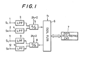
- L- and R-channel analog audio signals S L and S R respectively supplied to input terminals 1 and 2 are converted into digital audio signals by a common A/D converter 5 respectively through low-pass filters 3 and 4.
- oversampling is performed at a frequency 2f s , ie, twice a normal sampling frequency f s .
- the signals S L and S R are alternately sampled in the order of S L , S R , S, S R , ..., starting from SL. Therefore, in order to obtain a sampling rate of 2f s for each of the two-channel signals, a sampling clock of a frequency of 2f s ⁇ 2 is supplied to the A/D converter 5.
- the 2-channel digital signals obtained from the A/D converter 5 are supplied to a digital low-pass filter (to be referred to "digital filter” hereinafter) 6.
- digital filter the sampling rate of 2f s is converted to a normal sampling rate of f s .
- the digital signals are supplied to a digital recording and reproducing circuit 7, and are recorded on a magnetic tape.
- the L- and R-channel digital signals reproduced from the magnetic tape are respectively supplied from the recording and reproducing circuit 7 to the digital filter 6, and are sampled at the sampling rate f s . Thereafter, the digital signals are supplied to a common D/A converter 8. Sampling is started from the L channel at the sampling rate of 2f s , and the digital signals are alternately oversampled in the order L, R, L, R, ..., to be converted to analog signals.
- the analog signals are derived from output terminals 11 and 12 as reproduced original signals S L and S R through low-pass filters 9 and 10.
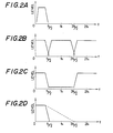
- the oversampling is performed by the A/D converter 5 in the recording mode and by the D/A converter 8 in the reproducing mode, so that design of the low-pass filters 3, 4, 9 and 10 can be facilitated. That is, assuming that the analog audio signals S L and S R have a bandwidth of about 0 to f s /2, as shown in fig 2A, recording and reproducing signals to and from the recording and reproducing circuit 7 have attenuation characteristics near f s /2 and 3f s /2, as shown in fig 2B.
- the digital filter 6 a filter having filter characteristics for attenuating an input within the range of f s /2 to 3f s /2, as shown in fig 2C. Therefore, the low-pass filters 3, 4, 9 and 10 can allow a signal with the spectrum shown in fig 2A to pass therethrough and can remove a signal of 3f s /2 or higher as in fig 2C.
- the filters can have a moderate attenuation characteristic curve as indicated by tge dotted line in fig 2D.
- the oversampling frequency is set to twice the normal frequency f s . If the magnification of the oversampling rate is further increased, the inclination of the characteristic curve of the low-pass filter can be further decreased.
- L- and R-channel signals are alternately recorded on the magnetic tape without any phase difference therebetween.
- the signals S L and S R passing through the low-pass filters 3 and 4 are alternately sampled in the order L, R, ..., from the L channel by the A/D converter 5, and are supplied to the digital filter 6.
- L- and R-channel signal processing operations are started at the same time. For this reason, the L-channel signal output from the digital filter 6 is phase-delayed from the R-channel signal output therefrom, and these signals are recorded on the magnetic tape with a phase difference.
- the 2-channel signals which are recorded on the magnetic tape with no phase difference are reproduced, and are simultaneously subjected to signal processing by the digital filter 6. Thereafter, these signals are alternately sampled by the D/A converter 8 in the order of L, R, ..., from the L channel.
- the L-channel signal output from the D/A converter 8 is phase-advanced from the R-channel signal.
- the 2-channel reproduced signals supplied to 2-channel loudspeakers thus have a phase difference therebetween impairing stability and the stereophonic effect of the sound.
- Japanese Patent Laid-Open (Kokai) No 60-242717 discloses a technique for reproducing signals while matching L- and R-channel phases.
- this patent does not describe a recording/reproducing apparatus at all.
- a digital filter in a recording/reproducing apparatus comprising: an analog-to-digital converter and/or a digital-to-analog converter for 2-channel signals; and means for storing first and second multiplication coefficient groups providing predetermined filter characteristics and in interpolation relationship with each other, characterised in that the filter is operative such that in a recording mode, the first multiplication coefficient group is sued for the first channel signal, and the second multiplication coefficient group is used for the second channel signal, and in a reproducing mode, the second multiplication coefficient group is used for the first channel signal, and the first multiplication coefficient group is used for the second channel signal.
- the present invention can provide a digital filter which can obtain 2-channel signals without a phase difference in a recording/reproducing mode.
- the illustrated digital filter changes the magnification of oversampling with respect to a single-channel signal using the same circuit arrangement as that of a circuit for processing 2-channel signals and removes the phase difference between 2-channel signals in recording and reproducing modes such that multiplication coefficient groups for defining filter characteristics of a digital filter are switched in accordance with L-/R-channel signals.
- Fig 3 schematically shows a FIR type digital filter used for recording/reproducing 2-channel signals.
- An L- or R-channel input digital signal S I supplied to an input terminal 20 sequentially passes through a series of N delay elements 21.
- the delay time of each delay element 21 is set to be one sampling period 1/2f s when double-rate oversampling is performed.
- Outputs from the delay elements 21 are multiplied and weighted with a predetermined multiplication coefficient by corresponding coefficient devices 22, and are summed by an adder 23, thus outputting an output signal S O .
- the output signal S O has predetermined filter characteristics shown in fig 2C with respect to the input signal S I .
- the coefficient devices 22 have two groups of multiplication coefficients, ie, a C coefficient group of O, C1, C2, ..., C N-2 , C N-1 , and an F coefficient group of F1, F2, ..., F N .
- the coefficient devices 22 select and use one of the first and second multiplication coefficient groups.
- the C coefficient group is used in the recording mode of 2-channel signals. If the input signal S I is an L-channel signal, the C coefficient group is used. If the input signal S I is an R-channel signal, the F coefficient group is used. In the reproducing mode of the 2-channel signals, if the input signal S I is the L-channel signal, the F coefficient group is used, and if the input signal S I is the R-channel signal, the C coefficient group is used.
- Fig 4 shows an example of the impulse response characteristics of the digital filter of figure 3.
- the response characteristics represent a change in time of the output signal S O when an impulse is applied to the input terminal 20. More specifically, the impulse is sequentially delayed by the delay elements 21, and the respective delayed outputs are weighted by the corresponding coefficient devices 22. Thereafter these outputs are sequentially output through the adder 23.
- the interval between sampling points is TS/4 (1/4f s ).
- the length of the arrow at each sampling point corresponds to an impulse having a size corresponding to the coefficient of each coefficient device 22.
- the coefficients of the coefficient devices 22 are selected as described above, so that the filter characteristics in the case of double or four-time oversampling rate shown in fig 2C described above or in fig 7A to be described later can be obtained.
- the digital filter 6 simultaneously starts signal processing of signals supplied from the A/D converter 5 shown in fig 1 in the order L, R, L, R, .... Therefore, the L-channel signal output from the digital filter 6 is delayed relative to the R-channel signal output.
- the curve of the impulse response characteristics of the R-channel digital filter 6 can be delayed by T s /4 from the curve of the response characteristics of the L-channel digital filter 6.
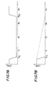
- Fig 5 shows the impulse response characteristics of the digital filter in a digital signal recording mode based on the above principle.
- the solid curve R indicated by “o” points represents the characteristics of the R-channel digital filter
- the dotted curve L indicated by “x” points represents characteristics of the L-channel digital filter.
- the curve R is delayed by T s /4 relative to the curve L.
- the size (height) of an impulse from a reference level indicated by “o” and “x” is determined such that "o” is determined by the F coefficient group and "x” is determined by the C coefficient group.
- the coefficients of the C and F coefficient groups are alternately set in fig 4.
- every other sampling point in fig 4 are selected to be classified into the C and F coefficient groups, and these coefficient groups are respectively used for the L- and R-channels. Therefore, the coefficients of the C and F coefficient groups in fig 5 are set to interpolate with each other with respect to the overall characteristics of the digital filter shown in fig 4. Note that signal processing is simultaneously started for the L- and R-channel signals.
- every other data sample enclosed shown by dotted lines is not output in practice. In fig 5, two sets of data are enclosed in the dotted lines.
- the 2-channel signals which are recorded on the magnetic tape without a phase difference are simultaneously subjected to signal processing by the digital filter 6 and are alternately sampled by the D/A converter 8 in the order of the L, R, ....
- the R-channel signal output from the D/A converter 8 is delayed from the L-channel signal by T s /4. Therefore, the digital filter 6 can perform correction such that the L-channel signal is delayed by T s /4. Therefore, the digital filter 6 can perform correction such that the L-channel signal is delayed by T s /4 from the R-channel signal.
- the curve of the impulse response characteristics of the L-channel digital filter 6 can be delayed by T s /4 relative to the curve of the impulse response characteristics of the R-channel digital filter 6.
- Fig 6 shows impulse response characteristics of the digital filter in a 2-channel signal reproducing mode based on the above principle.
- the curve L indicated by “o” points represents characteristics of the L-channel digital filter
- the curve R indicated by “x” points represents characteristics of the R-channel digital filter.
- the curve L is delayed by T x /4 relative to the curve R.
- the size (height) of an impulse from a reference level indicated by "o” and “x” is determined such that "o” is determined by the F coefficient group and "x” is determined by the C coefficient group.
- the coefficients of the C and F coefficient groups are set to interpolate with each other to provide the overall characteristics of the digital filter shown in fig 4.
- the recording and reproducing circuit 7 inserts zero data as every other data sample and supplies the data sample to the digital filter 6 in practice.
- the terminal 1 and the low-pass filter 3 or the terminal 2 and the low-pass filter 4 are omitted, and the terminal 11 and the low-pass filter 9 or the terminal 12 and the low-pass filter 10 are omitted.
- a single-channel input signal such as a monaural audio signal is supplied to the terminal 1 or 2, and a monaural reproduced analog audio signal is derived from the terminal 11 or 12. This case will be described below.
- a signal obtained from the low-pass filter 3 or 4 is converted by the A/D converter 5 to have a sampling rate 4f s .
- a signal which is oversampled at a four-times sampling rate is converted by the digital filter 6 to have a sampling rate f s , and is then supplied to the recording and reproducing circuit 7. Note that in order to convert the sampling rate 4f s into f s , every fourth data sample is output.
- the signal reproduced by the recording and reproducing circuit 7 is supplied to the D/A converter 8 through the digital filter 6, and is converted from f s to a sampling rate 4f s . Thereafter, the signal is supplied to the low-pass filter 9 or 10. Note that in order to convert a signal of a sampling rate f s from the digital filter 6 into a signal of a sampling rate of 4f s by the D/A converter 8, the recording and reproducing circuit 7 outputs the data sample at every fourth sampling point and inserts zero data samples therebetween, and supplies the resultant data to the digital filter 6.
- the digital filter 6 is used without modification, and a monaural signal can be oversampled at a four-time sampling rate without changing the clock frequency supplied to the A/D converter 5, the D/A converter 8 and the digital filter 6.
- the filter characteristics of the digital filter in this case have attenuation characteristics within the range of f s /2 to 7f s /2, as shown in fig 7A. Therefore, the low-pass filters 3, 4, 9 and 10 can have attenuation characteristics whose inclination is smaller than that of fig 2D, as indicated by a dotted line in fig 7B.
- all the coefficients of F and C coefficient groups shown in fig 3 are used and are alternately set.
- Fig 8 shows an embodiment of a digital filter for obtaining the filter characteristics shown in figs 2C and 7A.
- reference numeral 20 denotes an input terminal receiving a digital signal S I comprising 2-channel or single-channel serial data; 24, a shift register for sequentially receiving the digital signals S I from the input terminal 20 and converting them into parallel data; and 25, a switch for switching a magnification of oversampling.
- the switch 25 is switched between a four-times rate contact 254 and double-rate contact 252 in response to a magnification switching signal S C .
- Reference numerals 26 L and 26 R denote RAMs.
- the signals S I are monaural signals
- the data are sequentially written in both the RAM2 26 L and 26 R in accordance with a channel switching signal L/R; 28, a multiplier for receiving output data from the switch 27 at its one input terminal; and 29 C and 29 F , ROMs storing multiplication coefficient groups, respectively.
- the ROM 29 C stores the C coefficient group and the ROM 29 F stores the F coefficient group.
- Reference numeral 30 denotes a switch for switching the outputs from the ROMs 29 C and 29 F . In the recording mode, the switch 30 is connected to a contact C to supply the C coefficient group from the ROM 29 C to the outer input terminal of the multiplier 28 in the L-channel A/D conversion mode.
- the switch 30 is switched to a contact F to supply the F coefficient group form the ROM 29 F to the outer input terminal of the multiplier 28.
- the contacts C and F of the switch 30 are switched in a manner opposite to the recording mode.
- Reference numeral 31 denotes an adder for adding the multiplication output from the multiplier 28; and 32, an accumulator for latching the result from the adder 31. The output from the accumulator 32 is partially fed back to the adder 31, and is added to the multiplication output from the multiplier 28.
- Reference numeral 33 denotes a shift register for receiving output data from the accumulator 32 and converting it into serial data; and 34, an output terminal receiving an output signal S O derived from the shift register 33.
- the switch 25 is connected to the contact 252.
- the switch 27 is connected to the contact L and the switch 30 is connected to the contact C, respectively.
- the digital signal supplied from the input terminal 20 is delayed by a predetermined amount by the shift register 24 and the RAM 26 L . Thereafter, the delayed signal is supplied to the multiplier 28 through the switch 27 to be sequentially multiplied with the corresponding multiplication coefficients 0, C1, C2, ... from the ROM 29 C .
- the multiplication output from the multiplier 28 is sequentially supplied to the adder 31, and is added to the immediately preceding multiplication output, ie, the input fed back from the accumulator 32. The addition is repetitively performed.
- the output from the accumulator 32 is supplied to the shift register 33, and the content of the shift register 33 is obtained from the output terminal 34 as the desired L-channel digital signal.
- the switch 27 Upon reception of the R-channel signal, the switch 27 is switched to the contact R while the switch 30 is switched to the contact F.
- the digital signal from the input terminal 20 is delayed by a predetermined amount by the shift register 24, the switch 25, and the RAM 26 R , and is supplied to the multiplier 28 through the switch 27 to be sequentially multiplied with the corresponding multiplication coefficients F1, F2, ... from the ROM 29 F .
- the multiplication output from the multiplier 28 is supplied to the adder 31, and is added to the feedback input from the accumulator 32. The addition is repetitively performed.
- the output from the accumulator 32 is supplied to the shift register 32, and the contact of the shift register 32 is obtained from the output terminal 34 as the desired R-channel digital signal.
- the switches 27 and 30 are switched in a manner opposite to that described above, and the same operation as above is performed
- the digital filter is operated at the double sampling rate, and at this time, the filter characteristics shown in fig 2C are obtained.
- the switch 25 When a single-channel signal S I is supplied to the input terminal 20, the switch 25 is connected to the contact 254. In the recording and reproducing modes, the data from the shift register 24 are sequentially written in the RAMs 26 R and 26 L , and are supplied to the switch 27 which is alternately switched.
- the ROMS 29 C and 29 F are alternately subjected to read access, and the coefficients of the C and F coefficient groups are supplied to the multiplier 28 through the switch 30.
- the same operation as described above is performed, and the output signal S O can be obtained from the output terminal 34.
- the digital filter is operated at a four-times sampling rate, and at this time, the filter characteristics shown in fig 7A can be obtained.
- the single-channel signal can be one of the 2-channel signals.
- a digital filter having the circuit arrangement shown in fig 8 is used for the other channel signal.
- the 2-channel signal can be oversampled at a sampling rate of 4f s .
- the C and F coefficient groups defining the filter characteristics of the digital filter need only be switched in accordance with the recording/reproducing mode and the L-/R-channel signals.
- the phase difference between the 2-channel signals output from the digital filter can be removed in the recording mode, and the phase of one channel signal output from the digital filter to the D/A converter can be delayed from that of the other channel signal in the reproducing mode.
Landscapes
- Engineering & Computer Science (AREA)
- Physics & Mathematics (AREA)
- Computer Hardware Design (AREA)
- Mathematical Physics (AREA)
- Multimedia (AREA)
- Signal Processing (AREA)
- Signal Processing For Digital Recording And Reproducing (AREA)
Abstract
an analog-to-digital converter (5) and/or a digital-to-analog converter (8) for 2-channel signals; and
means (29C, 29F) for storing first and second multiplication coefficient groups providing predetermined filter characteristics and in interpolation relationship with each other, characterised in that the filter is operative such that
in a recording mode, the first multiplication coefficient group is sued for the first channel signal, and the second multiplication coefficient group is used for the second channel signal, and
in a reproducing mode, the second multiplication coefficient group is used for the first channel signal, and the first multiplication coefficient group is used for the second channel signal.
Description
- The present invention relates to a digital filter and, more particularly, to a digital filter used for a digital recording/reproducing apparatus.
- Recently, a digital recording/reproducing apparatus known as a digital audio tape (DAT) recorder has been developed. In such an apparatus, as shown in fig 1 of the accompanying drawings, in a recording mode, L- and R-channel analog audio signals SL and SR respectively supplied to
input terminals D converter 5 respectively through low-pass filters D converter 5. - The 2-channel digital signals obtained from the A/
D converter 5 are supplied to a digital low-pass filter (to be referred to "digital filter" hereinafter) 6. In thedigital filter 6, the sampling rate of 2fs is converted to a normal sampling rate of fs. Thereafter, the digital signals are supplied to a digital recording and reproducingcircuit 7, and are recorded on a magnetic tape. - During reproduction, the L- and R-channel digital signals reproduced from the magnetic tape are respectively supplied from the recording and reproducing
circuit 7 to thedigital filter 6, and are sampled at the sampling rate fs. Thereafter, the digital signals are supplied to a common D/A converter 8. Sampling is started from the L channel at the sampling rate of 2fs, and the digital signals are alternately oversampled in the order L, R, L, R, ..., to be converted to analog signals. The analog signals are derived fromoutput terminals pass filters - The oversampling is performed by the A/
D converter 5 in the recording mode and by the D/A converter 8 in the reproducing mode, so that design of the low-pass filters circuit 7 have attenuation characteristics near fs/2 and 3fs/2, as shown in fig 2B. - As the
digital filter 6, a filter having filter characteristics for attenuating an input within the range of fs/2 to 3fs/2, as shown in fig 2C, is employed. Therefore, the low-pass filters pass filters - In the above-mentioned digital recording/reproducing apparatus, it is preferable that L- and R-channel signals are alternately recorded on the magnetic tape without any phase difference therebetween.
- In the circuit shown in fig 1, in the recording mode, the signals SL and SR passing through the low-
pass filters D converter 5, and are supplied to thedigital filter 6. In thisdigital filter 6, L- and R-channel signal processing operations are started at the same time. For this reason, the L-channel signal output from thedigital filter 6 is phase-delayed from the R-channel signal output therefrom, and these signals are recorded on the magnetic tape with a phase difference. - In the reproducing mode, the 2-channel signals which are recorded on the magnetic tape with no phase difference are reproduced, and are simultaneously subjected to signal processing by the
digital filter 6. Thereafter, these signals are alternately sampled by the D/A converter 8 in the order of L, R, ..., from the L channel. As a result, the L-channel signal output from the D/A converter 8 is phase-advanced from the R-channel signal. The 2-channel reproduced signals supplied to 2-channel loudspeakers, thus have a phase difference therebetween impairing stability and the stereophonic effect of the sound. - In order to solve the above problems, two A/D and D/A converters can be provided for each of the 2-channel, ie, L-and R-channel signals. However, the resulting circuit arrangement is complicated and cost is increased.
- Japanese Patent Laid-Open (Kokai) No 60-242717 discloses a technique for reproducing signals while matching L- and R-channel phases. However, this patent does not describe a recording/reproducing apparatus at all. According to the present invention, there is provided a digital filter in a recording/reproducing apparatus comprising:
an analog-to-digital converter and/or a digital-to-analog converter for 2-channel signals; and
means for storing first and second multiplication coefficient groups providing predetermined filter characteristics and in interpolation relationship with each other, characterised in that the filter is operative such that
in a recording mode, the first multiplication coefficient group is sued for the first channel signal, and the second multiplication coefficient group is used for the second channel signal, and
in a reproducing mode, the second multiplication coefficient group is used for the first channel signal, and the first multiplication coefficient group is used for the second channel signal. - As will become apparent from the following description, the present invention can provide a digital filter which can obtain 2-channel signals without a phase difference in a recording/reproducing mode. The illustrated digital filter changes the magnification of oversampling with respect to a single-channel signal using the same circuit arrangement as that of a circuit for processing 2-channel signals and removes the phase difference between 2-channel signals in recording and reproducing modes such that multiplication coefficient groups for defining filter characteristics of a digital filter are switched in accordance with L-/R-channel signals.
- The invention will be further described by way of non-limitative example with reference to the accompanying drawings, in which:-
- Fig 1 is a block diagram showing a prior art circuit;
- Figs 2A to 2D are graphs showing characteristics of the circuit shown in fig 1;
- Fig 3 is a block diagram schematically showing a digital filter when 2-channel signals are recorded/reproduced;
- Fig 4 is a graph showing impulse response characteristics of a digital filter;
- Fig 5 is a graph showing impulse response characteristics for L- and R-channels in the recording mode;
- Fig 6 is a graph showing impulse response characteristics for L- and R-channels in the reproducing mode;
- Figs 7A and 7B are graphs showing filter characteristics when four-times oversampling is performed; and
- Fig 8 is a block diagram showing an embodiment of the present invention.
- Fig 3 schematically shows a FIR type digital filter used for recording/reproducing 2-channel signals. An L- or R-channel input digital signal SI supplied to an
input terminal 20 sequentially passes through a series ofN delay elements 21. The delay time of eachdelay element 21 is set to be onesampling period 1/2fs when double-rate oversampling is performed. - Outputs from the
delay elements 21 are multiplied and weighted with a predetermined multiplication coefficient bycorresponding coefficient devices 22, and are summed by anadder 23, thus outputting an output signal SO. The output signal SO has predetermined filter characteristics shown in fig 2C with respect to the input signal SI. Thecoefficient devices 22 have two groups of multiplication coefficients, ie, a C coefficient group of O, C₁, C₂, ..., CN-2, CN-1, and an F coefficient group of F₁, F₂, ..., FN. Thecoefficient devices 22 select and use one of the first and second multiplication coefficient groups. - In this embodiment, in the recording mode of 2-channel signals, if the input signal SI is an L-channel signal, the C coefficient group is used. If the input signal SI is an R-channel signal, the F coefficient group is used. In the reproducing mode of the 2-channel signals, if the input signal SI is the L-channel signal, the F coefficient group is used, and if the input signal SI is the R-channel signal, the C coefficient group is used.
- Fig 4 shows an example of the impulse response characteristics of the digital filter of figure 3.
- The response characteristics represent a change in time of the output signal SO when an impulse is applied to the
input terminal 20. More specifically, the impulse is sequentially delayed by thedelay elements 21, and the respective delayed outputs are weighted by thecorresponding coefficient devices 22. Thereafter these outputs are sequentially output through theadder 23. - In this impulse response characteristics, the interval between sampling points (output timings of the delay elements 21) is TS/4 (1/4fs). The length of the arrow at each sampling point corresponds to an impulse having a size corresponding to the coefficient of each
coefficient device 22. The coefficients of thecoefficient devices 22 are selected as described above, so that the filter characteristics in the case of double or four-time oversampling rate shown in fig 2C described above or in fig 7A to be described later can be obtained. - As described above, in the 2-channel signal recording mode, the
digital filter 6 simultaneously starts signal processing of signals supplied from the A/D converter 5 shown in fig 1 in the order L, R, L, R, .... Therefore, the L-channel signal output from thedigital filter 6 is delayed relative to the R-channel signal output. The delay is Ts/4 with respect to 1/2 of a sampling period 2fs, ie, a normal sampling period Ts (= 1/fs). Therefore, thedigital filter 6 can perform correction such that the R-channel signal is delayed by Ts/4 with respect to the L-channel signal. For this purpose, the curve of the impulse response characteristics of the R-channeldigital filter 6 can be delayed by Ts/4 from the curve of the response characteristics of the L-channeldigital filter 6. - Fig 5 shows the impulse response characteristics of the digital filter in a digital signal recording mode based on the above principle. The solid curve R indicated by "o" points represents the characteristics of the R-channel digital filter, and the dotted curve L indicated by "x" points represents characteristics of the L-channel digital filter. The curve R is delayed by Ts/4 relative to the curve L. The size (height) of an impulse from a reference level indicated by "o" and "x" is determined such that "o" is determined by the F coefficient group and "x" is determined by the C coefficient group. The coefficients of the C and F coefficient groups are alternately set in fig 4. In this invention, every other sampling point in fig 4 are selected to be classified into the C and F coefficient groups, and these coefficient groups are respectively used for the L- and R-channels. Therefore, the coefficients of the C and F coefficient groups in fig 5 are set to interpolate with each other with respect to the overall characteristics of the digital filter shown in fig 4. Note that signal processing is simultaneously started for the L- and R-channel signals. In order to convert the sampling rate 2fs from the A/
D converter 5 into a sampling rate fs, every other data sample enclosed shown by dotted lines is not output in practice. In fig 5, two sets of data are enclosed in the dotted lines. - In the reproducing mode of the 2-channel signals recorded as described above, the 2-channel signals which are recorded on the magnetic tape without a phase difference are simultaneously subjected to signal processing by the
digital filter 6 and are alternately sampled by the D/A converter 8 in the order of the L, R, .... In this case, the R-channel signal output from the D/A converter 8 is delayed from the L-channel signal by Ts/4. Therefore, thedigital filter 6 can perform correction such that the L-channel signal is delayed by Ts/4. Therefore, thedigital filter 6 can perform correction such that the L-channel signal is delayed by Ts/4 from the R-channel signal. For this purpose, the curve of the impulse response characteristics of the L-channeldigital filter 6 can be delayed by Ts/4 relative to the curve of the impulse response characteristics of the R-channeldigital filter 6. - Fig 6 shows impulse response characteristics of the digital filter in a 2-channel signal reproducing mode based on the above principle. The curve L indicated by "o" points represents characteristics of the L-channel digital filter, and the curve R indicated by "x" points represents characteristics of the R-channel digital filter. The curve L is delayed by Tx/4 relative to the curve R. The size (height) of an impulse from a reference level indicated by "o" and "x" is determined such that "o" is determined by the F coefficient group and "x" is determined by the C coefficient group. The coefficients of the C and F coefficient groups are set to interpolate with each other to provide the overall characteristics of the digital filter shown in fig 4. In order to convert a signal of the sampling rate fs from the
digital filter 6 into a signal having sampling rate twice fs, ie, 2fs by the D/A converter 8, the recording and reproducingcircuit 7 inserts zero data as every other data sample and supplies the data sample to thedigital filter 6 in practice. - A case will be described wherein a single-channel signal is recorded/reproduced.
- In fig 1, the
terminal 1 and the low-pass filter 3 or theterminal 2 and the low-pass filter 4 are omitted, and the terminal 11 and the low-pass filter 9 or the terminal 12 and the low-pass filter 10 are omitted. In addition, a single-channel input signal such as a monaural audio signal is supplied to theterminal - In the recording mode, a signal obtained from the low-
pass filter D converter 5 to have a sampling rate 4fs. A signal which is oversampled at a four-times sampling rate is converted by thedigital filter 6 to have a sampling rate fs, and is then supplied to the recording and reproducingcircuit 7. Note that in order to convert the sampling rate 4fs into fs, every fourth data sample is output. - In the reproducing mode, the signal reproduced by the recording and reproducing
circuit 7 is supplied to the D/A converter 8 through thedigital filter 6, and is converted from fs to a sampling rate 4fs. Thereafter, the signal is supplied to the low-pass filter digital filter 6 into a signal of a sampling rate of 4fs by the D/A converter 8, the recording and reproducingcircuit 7 outputs the data sample at every fourth sampling point and inserts zero data samples therebetween, and supplies the resultant data to thedigital filter 6. - As described above, the
digital filter 6 is used without modification, and a monaural signal can be oversampled at a four-time sampling rate without changing the clock frequency supplied to the A/D converter 5, the D/A converter 8 and thedigital filter 6. The filter characteristics of the digital filter in this case have attenuation characteristics within the range of fs/2 to 7fs/2, as shown in fig 7A. Therefore, the low-pass filters - Fig 8 shows an embodiment of a digital filter for obtaining the filter characteristics shown in figs 2C and 7A.
- In fig 8,
reference numeral 20 denotes an input terminal receiving a digital signal SI comprising 2-channel or single-channel serial data; 24, a shift register for sequentially receiving the digital signals SI from theinput terminal 20 and converting them into parallel data; and 25, a switch for switching a magnification of oversampling. Theswitch 25 is switched between a four-times rate contact 25₄ and double-rate contact 25₂ in response to a magnification switching signal SC. Reference numerals 26L and 26R denote RAMs. When the signals SI are monaural signals, the data are sequentially written in both the RAM2 26L and 26R in accordance with a channel switching signal L/R; 28, a multiplier for receiving output data from theswitch 27 at its one input terminal; and 29C and 29F, ROMs storing multiplication coefficient groups, respectively. The ROM 29C stores the C coefficient group and the ROM 29F stores the F coefficient group.Reference numeral 30 denotes a switch for switching the outputs from the ROMs 29C and 29F. In the recording mode, theswitch 30 is connected to a contact C to supply the C coefficient group from the ROM 29C to the outer input terminal of themultiplier 28 in the L-channel A/D conversion mode. In the R-channel A/D conversion mode, theswitch 30 is switched to a contact F to supply the F coefficient group form the ROM 29F to the outer input terminal of themultiplier 28. In the reproducing mode, the contacts C and F of theswitch 30 are switched in a manner opposite to the recording mode. -
Reference numeral 31 denotes an adder for adding the multiplication output from themultiplier 28; and 32, an accumulator for latching the result from theadder 31. The output from theaccumulator 32 is partially fed back to theadder 31, and is added to the multiplication output from themultiplier 28.Reference numeral 33 denotes a shift register for receiving output data from theaccumulator 32 and converting it into serial data; and 34, an output terminal receiving an output signal SO derived from theshift register 33. - The circuit operation of the above arrangement will be described hereinafter.
- In the 2-channel signal recording mode, the
switch 25 is connected to thecontact 25₂. Upon reception of the L-channel signal, theswitch 27 is connected to the contact L and theswitch 30 is connected to the contact C, respectively. The digital signal supplied from theinput terminal 20 is delayed by a predetermined amount by theshift register 24 and the RAM 26L. Thereafter, the delayed signal is supplied to themultiplier 28 through theswitch 27 to be sequentially multiplied with thecorresponding multiplication coefficients 0, C₁, C₂, ... from the ROM 29C. The multiplication output from themultiplier 28 is sequentially supplied to theadder 31, and is added to the immediately preceding multiplication output, ie, the input fed back from theaccumulator 32. The addition is repetitively performed. The output from theaccumulator 32 is supplied to theshift register 33, and the content of theshift register 33 is obtained from theoutput terminal 34 as the desired L-channel digital signal. - Upon reception of the R-channel signal, the
switch 27 is switched to the contact R while theswitch 30 is switched to the contact F. The digital signal from theinput terminal 20 is delayed by a predetermined amount by theshift register 24, theswitch 25, and the RAM 26R, and is supplied to themultiplier 28 through theswitch 27 to be sequentially multiplied with the corresponding multiplication coefficients F₁, F₂, ... from the ROM 29F. The multiplication output from themultiplier 28 is supplied to theadder 31, and is added to the feedback input from theaccumulator 32. The addition is repetitively performed. The output from theaccumulator 32 is supplied to theshift register 32, and the contact of theshift register 32 is obtained from theoutput terminal 34 as the desired R-channel digital signal. - In the 2-channel signal reproducing mode, the
switches - With the above operation, the digital filter is operated at the double sampling rate, and at this time, the filter characteristics shown in fig 2C are obtained.
- When a single-channel signal SI is supplied to the
input terminal 20, theswitch 25 is connected to thecontact 25₄. In the recording and reproducing modes, the data from theshift register 24 are sequentially written in the RAMs 26R and 26L, and are supplied to theswitch 27 which is alternately switched. The ROMS 29C and 29F are alternately subjected to read access, and the coefficients of the C and F coefficient groups are supplied to themultiplier 28 through theswitch 30. Thus, the same operation as described above is performed, and the output signal SO can be obtained from theoutput terminal 34. - As described above, the digital filter is operated at a four-times sampling rate, and at this time, the filter characteristics shown in fig 7A can be obtained.
- Note that the single-channel signal can be one of the 2-channel signals. In this case, a digital filter having the circuit arrangement shown in fig 8 is used for the other channel signal. In this case, the 2-channel signal can be oversampled at a sampling rate of 4fs.
- Therefore, the C and F coefficient groups defining the filter characteristics of the digital filter need only be switched in accordance with the recording/reproducing mode and the L-/R-channel signals. The phase difference between the 2-channel signals output from the digital filter can be removed in the recording mode, and the phase of one channel signal output from the digital filter to the D/A converter can be delayed from that of the other channel signal in the reproducing mode. By using the same circuit arrangement, the magnification of oversampling for the single-channel signal can be changed.
Claims (6)
an analog-to-digital converter (5) and/or a digital-to-analog converter (8) for 2-channel signals; and
means (29C, 29F) for storing first and second multiplication coefficient groups providing predetermined filter characteristics and in interpolation relationship with each other, characterised in that the filter is operative such that
in a recording mode, the first multiplication coefficient group is sued for the first channel signal, and the second multiplication coefficient group is used for the second channel signal, and
in a reproducing mode, the second multiplication coefficient group is used for the first channel signal, and the first multiplication coefficient group is used for the second channel signal.
Applications Claiming Priority (4)
| Application Number | Priority Date | Filing Date | Title |
|---|---|---|---|
| JP43808/87 | 1987-02-26 | ||
| JP4380887A JPS63209317A (en) | 1987-02-26 | 1987-02-26 | Fir type digital filter in recording and reproducing device |
| JP207860/87 | 1987-08-21 | ||
| JP20786087A JPS6450615A (en) | 1987-08-21 | 1987-08-21 | Fir type digital filter in recording and reproducing device |
Publications (3)
| Publication Number | Publication Date |
|---|---|
| EP0280575A2 true EP0280575A2 (en) | 1988-08-31 |
| EP0280575A3 EP0280575A3 (en) | 1990-09-26 |
| EP0280575B1 EP0280575B1 (en) | 1994-09-14 |
Family
ID=26383643
Family Applications (1)
| Application Number | Title | Priority Date | Filing Date |
|---|---|---|---|
| EP88301702A Expired - Lifetime EP0280575B1 (en) | 1987-02-26 | 1988-02-26 | Fir type digital filter for recording and reproducing apparatus |
Country Status (3)
| Country | Link |
|---|---|
| US (1) | US4853797A (en) |
| EP (1) | EP0280575B1 (en) |
| DE (1) | DE3851450T2 (en) |
Families Citing this family (6)
| Publication number | Priority date | Publication date | Assignee | Title |
|---|---|---|---|---|
| US4932880A (en) * | 1989-04-07 | 1990-06-12 | The United States Of America As Represented By The Secretary Of The Navy | Low-cost sound related trainer |
| JP3137995B2 (en) * | 1991-01-31 | 2001-02-26 | パイオニア株式会社 | PCM digital audio signal playback device |
| KR0135510B1 (en) * | 1991-03-30 | 1998-04-22 | 강진구 | Long time multi-channel data tape recorder with data |
| US5327298A (en) * | 1992-09-10 | 1994-07-05 | International Business Machines Corporation | Noise minimization for magnetic data storage drives using oversampling techniques |
| US5325247A (en) * | 1992-11-12 | 1994-06-28 | Quantum Corporation | Digital multi-rate notch filter for sampled servo digital control system |
| GB2293288B (en) * | 1994-09-15 | 1998-09-23 | Sony Uk Ltd | Conversion between analogue and digital signals |
Citations (4)
| Publication number | Priority date | Publication date | Assignee | Title |
|---|---|---|---|---|
| EP0155101A1 (en) * | 1984-02-21 | 1985-09-18 | Mitsubishi Denki Kabushiki Kaisha | Method and Apparatus for Magnetic Recording and Reproducing |
| JPS60242717A (en) * | 1984-05-17 | 1985-12-02 | Sony Corp | Fir-type digital filter |
| FR2566604A1 (en) * | 1984-06-20 | 1985-12-27 | Bosch Gmbh Robert | RECEIVER OF RECORDED DATA |
| EP0173307A2 (en) * | 1984-08-31 | 1986-03-05 | Hitachi, Ltd. | Nonrecursive digital filter |
Family Cites Families (2)
| Publication number | Priority date | Publication date | Assignee | Title |
|---|---|---|---|---|
| DE3373952D1 (en) * | 1982-11-19 | 1987-11-05 | Hitachi Ltd | Multitrack pcm reproducing apparatus |
| JPH07122966B2 (en) * | 1984-03-19 | 1995-12-25 | 株式会社日立製作所 | Recording method and reproducing method of rotary head type PCM recorder |
-
1988
- 1988-02-25 US US07/160,483 patent/US4853797A/en not_active Expired - Fee Related
- 1988-02-26 DE DE3851450T patent/DE3851450T2/en not_active Expired - Fee Related
- 1988-02-26 EP EP88301702A patent/EP0280575B1/en not_active Expired - Lifetime
Patent Citations (4)
| Publication number | Priority date | Publication date | Assignee | Title |
|---|---|---|---|---|
| EP0155101A1 (en) * | 1984-02-21 | 1985-09-18 | Mitsubishi Denki Kabushiki Kaisha | Method and Apparatus for Magnetic Recording and Reproducing |
| JPS60242717A (en) * | 1984-05-17 | 1985-12-02 | Sony Corp | Fir-type digital filter |
| FR2566604A1 (en) * | 1984-06-20 | 1985-12-27 | Bosch Gmbh Robert | RECEIVER OF RECORDED DATA |
| EP0173307A2 (en) * | 1984-08-31 | 1986-03-05 | Hitachi, Ltd. | Nonrecursive digital filter |
Non-Patent Citations (1)
| Title |
|---|
| PATENT ABSTRACTS OF JAPAN vol. 10, no. 104 (E-397)(2161) 19 April 1986, & JP-A-60 242 717 (SONY K.K.) 2 December 1985 * |
Also Published As
| Publication number | Publication date |
|---|---|
| DE3851450D1 (en) | 1994-10-20 |
| EP0280575A3 (en) | 1990-09-26 |
| DE3851450T2 (en) | 1995-02-02 |
| US4853797A (en) | 1989-08-01 |
| EP0280575B1 (en) | 1994-09-14 |
Similar Documents
| Publication | Publication Date | Title |
|---|---|---|
| US3991277A (en) | Frequency division multiplex system using comb filters | |
| EP0137464B1 (en) | A digital signal processing apparatus having a digital filter | |
| EP0305864B1 (en) | Improved sampling frequency converter for converting a lower sampling frequency to a higher sampling frequency and a method therefor | |
| EP0497060A2 (en) | PCM digital audio signal playback apparatus | |
| EP0280575B1 (en) | Fir type digital filter for recording and reproducing apparatus | |
| US5825756A (en) | Receiver for FM data multiplex broadcasting | |
| EP0129236B1 (en) | Signal conversion apparatus for use in pcm signal processing system | |
| EP0382245B1 (en) | Color component signal converting apparatus | |
| US5661478A (en) | Conversion between analogue and digital signals | |
| US5572210A (en) | Digital signal processing apparatus | |
| US6772022B1 (en) | Methods and apparatus for providing sample rate conversion between CD and DAT | |
| CA1307584C (en) | Velocity error generator with first-order interpolation | |
| KR100484398B1 (en) | 1-bit digital signal processor, recorder and playback device | |
| JPH0732343B2 (en) | Asynchronous sampling frequency conversion method | |
| JPH0193211A (en) | Signal conversion device | |
| JP2580102B2 (en) | FIR digital filter | |
| US3942126A (en) | Band-pass filter for frequency modulated signal transmission | |
| JPH0671193B2 (en) | Non-cyclic digital filter | |
| JPH04152779A (en) | Nonlinear digital signal processing circuit | |
| JPS6316472A (en) | Reproducing device | |
| JPS63209317A (en) | Fir type digital filter in recording and reproducing device | |
| JPS62173900A (en) | Digital audio signal reproducing device | |
| JPH0250507A (en) | Sampling frequency converter | |
| JPS62122423A (en) | Digital-analog conversion circuit | |
| JPH01296706A (en) | Digital filter |
Legal Events
| Date | Code | Title | Description |
|---|---|---|---|
| PUAI | Public reference made under article 153(3) epc to a published international application that has entered the european phase |
Free format text: ORIGINAL CODE: 0009012 |
|
| AK | Designated contracting states |
Kind code of ref document: A2 Designated state(s): DE FR GB NL |
|
| PUAL | Search report despatched |
Free format text: ORIGINAL CODE: 0009013 |
|
| RHK1 | Main classification (correction) |
Ipc: H03H 17/06 |
|
| AK | Designated contracting states |
Kind code of ref document: A3 Designated state(s): DE FR GB NL |
|
| 17P | Request for examination filed |
Effective date: 19910305 |
|
| 17Q | First examination report despatched |
Effective date: 19931115 |
|
| GRAA | (expected) grant |
Free format text: ORIGINAL CODE: 0009210 |
|
| AK | Designated contracting states |
Kind code of ref document: B1 Designated state(s): DE FR GB NL |
|
| REF | Corresponds to: |
Ref document number: 3851450 Country of ref document: DE Date of ref document: 19941020 |
|
| ET | Fr: translation filed | ||
| PGFP | Annual fee paid to national office [announced via postgrant information from national office to epo] |
Ref country code: DE Payment date: 19950222 Year of fee payment: 8 |
|
| PG25 | Lapsed in a contracting state [announced via postgrant information from national office to epo] |
Ref country code: GB Effective date: 19950226 |
|
| PLBE | No opposition filed within time limit |
Free format text: ORIGINAL CODE: 0009261 |
|
| STAA | Information on the status of an ep patent application or granted ep patent |
Free format text: STATUS: NO OPPOSITION FILED WITHIN TIME LIMIT |
|
| PG25 | Lapsed in a contracting state [announced via postgrant information from national office to epo] |
Ref country code: NL Effective date: 19950901 |
|
| 26N | No opposition filed | ||
| GBPC | Gb: european patent ceased through non-payment of renewal fee |
Effective date: 19950226 |
|
| PG25 | Lapsed in a contracting state [announced via postgrant information from national office to epo] |
Ref country code: FR Effective date: 19951031 |
|
| NLV4 | Nl: lapsed or anulled due to non-payment of the annual fee |
Effective date: 19950901 |
|
| REG | Reference to a national code |
Ref country code: FR Ref legal event code: ST |
|
| PG25 | Lapsed in a contracting state [announced via postgrant information from national office to epo] |
Ref country code: DE Effective date: 19961101 |