EP0280522A2 - Stellglied mit eingebautem Pilotventil - Google Patents
Stellglied mit eingebautem Pilotventil Download PDFInfo
- Publication number
- EP0280522A2 EP0280522A2 EP88301568A EP88301568A EP0280522A2 EP 0280522 A2 EP0280522 A2 EP 0280522A2 EP 88301568 A EP88301568 A EP 88301568A EP 88301568 A EP88301568 A EP 88301568A EP 0280522 A2 EP0280522 A2 EP 0280522A2
- Authority
- EP
- European Patent Office
- Prior art keywords
- piston
- spool
- land
- communicating
- port
- Prior art date
- Legal status (The legal status is an assumption and is not a legal conclusion. Google has not performed a legal analysis and makes no representation as to the accuracy of the status listed.)
- Withdrawn
Links
Images


Classifications
-
- F—MECHANICAL ENGINEERING; LIGHTING; HEATING; WEAPONS; BLASTING
- F16—ENGINEERING ELEMENTS AND UNITS; GENERAL MEASURES FOR PRODUCING AND MAINTAINING EFFECTIVE FUNCTIONING OF MACHINES OR INSTALLATIONS; THERMAL INSULATION IN GENERAL
- F16H—GEARING
- F16H63/00—Control outputs from the control unit to change-speed- or reversing-gearings for conveying rotary motion or to other devices than the final output mechanism
- F16H63/02—Final output mechanisms therefor; Actuating means for the final output mechanisms
- F16H63/30—Constructional features of the final output mechanisms
- F16H63/3023—Constructional features of the final output mechanisms the final output mechanisms comprising elements moved by fluid pressure
-
- F—MECHANICAL ENGINEERING; LIGHTING; HEATING; WEAPONS; BLASTING
- F16—ENGINEERING ELEMENTS AND UNITS; GENERAL MEASURES FOR PRODUCING AND MAINTAINING EFFECTIVE FUNCTIONING OF MACHINES OR INSTALLATIONS; THERMAL INSULATION IN GENERAL
- F16H—GEARING
- F16H59/00—Control inputs to control units of change-speed-, or reversing-gearings for conveying rotary motion
- F16H59/14—Inputs being a function of torque or torque demand
-
- F—MECHANICAL ENGINEERING; LIGHTING; HEATING; WEAPONS; BLASTING
- F16—ENGINEERING ELEMENTS AND UNITS; GENERAL MEASURES FOR PRODUCING AND MAINTAINING EFFECTIVE FUNCTIONING OF MACHINES OR INSTALLATIONS; THERMAL INSULATION IN GENERAL
- F16H—GEARING
- F16H59/00—Control inputs to control units of change-speed-, or reversing-gearings for conveying rotary motion
- F16H59/36—Inputs being a function of speed
- F16H59/38—Inputs being a function of speed of gearing elements
- F16H59/42—Input shaft speed
Definitions
- the present invention relates to an actuator of a compact size with a built-in pilot valve for producing a relatively large operating force in a small range of working oil differential pressures.
- Hydraulically operated actuators include double-acting cylinders for producing operating forces in opposite directions dependent on the difference between pressures acting on both ends of the piston.
- the operating force produced by the piston will be quite small when the differential pressure is relatively low, so that the actuator may operate slowly or fail to operate.
- One solution would be to employ a servovalve for enabling the piston to generate a large operating force even in a small range of working oil differential pressures.
- the size of the actuator would be increased since the servovalve would be attached outside of the cylinder. If a pilot valve were used instead, a large operating force would be produced with a small differential pressure, but the actuator would be of a large size as the pilot valve would also be installed outside of the cylinder.
- Another problem would be that operation of the acutator might become unstable in some cases since a large operating force would be produced with a small differential pressure.
- an actuator with a built-in pilot valve comprising a cylinder tube having first and second cylinder chambers coaxially defined therein, a piston having first and second piston lands slidably and fluid-tightly disposed respectively in the first and second cylinder chambers, and having a piston rod as an operating end, the piston having an axial inner hole defined therein and having closed opposite ends, a spool valve body axially movably and fluid-tightly disposed in the inner hole and having first and second spool lands, first and second axial passages defined in the piston and extending axially inwardly from front surfaces of the piston lands, respectively, the first and second axial passages being held out of communication with each other, a first inlet port for communicating a portion of the first cylinder chamber behind the first piston land with a first external pressure source, a second inlet port for communicating a portion of the second cylinder chamber behind the second piston land with a second external pressure source, a first communication port communicating the portion of
- the actuator With a pilot valve incorporated in the piston of the actuator, the operating force on the piston can be amplified. Therefore, even if the difference between applied working oil pressures is small, a large operating force an be generated.
- the actuator is compact in size.
- At least one of the communication ports may have a restriction, or the first and second spool lands may uncover the respective first and second supply ports, for stabler actuator operation.
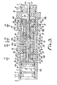
- FIG. 1 shows in axial cross section an actuator with a built-in pilot valve according to an embodiment of the present invention.
- the actuator may be used as an actuator for controlling a continuously variable transmission, for example, for use with a motor vehicle such as an automobile.
- a cylinder tube 1 of a cylindrical shape has open opposite ends.
- a cover 2 is fixedly fitted in the lefthand (FIG. 1) open end of the cylinder tube 1 to close the lefthand open end.
- An O-ring 6 is interposed between the inner peripheral surface of the lefthand open end of the cylinder tube 1 and the cover 2 to provide a fluid-tight seal therebetween.
- the cover 2 has an annular step 3 on its outer peripheral surface, the annular step 3 being held against a corresponding step 4 on the inner peripheral surface of the cylinder tube 1.
- the cover 2 is retained in place by a C-ring 5.
- a flanged cover 7 is fixedly fitted in the righthand (FIG. 1) open end of the cylinder tube 1 to close the righthand open end.
- An O-ring 10 is interposed between the inner peripheral surface of the righthand open end of the cylinder tube 1 and the cover 7 to provide a fluid-tight seal therebetween.
- the flanged cover 7 has a flange 8 retained in place by being sandwiched between an end 9 of the cylinder tube 1 and a bracket (not shown) to which the cylinder tube 1 is fixed.
- a pair of partitions 11, 12 are disposed centrally in the cylinder tube 1 in axially spaced, confronting relation to each other.
- the cylinder tube 1 has a downward opening between the partitions 11, 12.
- the interior of the cylinder tube 1 is divided by the partitions 11, 12 into three chambers, i.e., a central atmospheric chamber 13 and cylinder chambers 14, 15 one on each side of the chamber 13.
- the partitions 11, 12 have respective axial holes 16, 17 formed in coaxial relation to each other.
- a piston 18 extends through the holes 16, 17 into the cylinder chambers 14, 15.
- the piston 18 is substantially symmetrical in shape with respect to an axially central portion thereof, and comprises two axially separable members. At the center of the piston 18, the separable members are firmly coupled to each other at confronting portions thereof by a bayonet-type coupling 60, thereby completing the piston 18.
- the piston 18 is in the form of a bobbin having disc-shaped lands 19, 20, respectively, at its opposite ends and cylindrical barrels 21, 22 of reduced diameter between the lands 19, 20.
- the barrels 21, 22 are slidably supported respectively in the holes 16, 17.
- the lands 19, 20 are axially slidably disposed in the cylinder chambers 14, 15, respectively, with O-rings 19a, 20a mounted in the outer peripheral surfaces of the lands 19, 20, respectively, and slidable against the inner peripheral surfaces of the cylinder chambers 14, 15.
- the barrels 21, 22 have respective inner holes 23, 24 communicating axially with each other and extending to positions near the lands 19, 20.
- the coupling 60 which joins the barrels 21, 22 to each other has a drain hole 25 through which the inner holes 23, 24 communicate with the atmospheric chamber 13.
- a pair of confronting plungers 26, 27 are axially slidably housed in the inner holes 23, 24, respectively.
- the plungers 26, 27 have smaller-diameter projections 26a, 27a, respectively, on confronting ends thereof, and are held against each other through the smaller-diameter projections 26a, 27a.
- the plungers 26, 27 are normally urged toward each other for coaction by compression coil springs 33, 34 (described later), respectively. Therefore, the plungers 26, 27 functionally serve as a single spool valve body having lands on opposite ends thereof.
- the plungers 26, 27 have holes 29, 30, respectively, defined axially therein and extending from inner walls 28 of the lefthand and righthand ends of the inner holes 23, 24 toward the confronting ends of the plungers 26, 27.
- the compression coil springs 33, 34 are accommodated respectively in the holes 29, 30.
- the compression coil springs 33, 34 have ends borne by the bottom surfaces of the holes 29, 30.
- Rod-shaped stoppers 31, 32 project axially into the respective compression coil springs 33, 34 and have outer flanges 35, 36, respectively, on their base ends.
- the outer flanges 35, 36 are clamped between the other ends of the compression coil springs 33, 34 and the inner walls 28. Therefore, the plungers 26, 27 are resiliently biased into abutment against each other.
- the plungers 26, 27 have annular grooves 37 defined in their outer peripheral surfaces at spaced intervals for allowing the plungers 26, 27 to slide smoothly in the inner holes 23, 24.
- the cylinder tube 1 has a governor pressure inlet port 38 for receiving a governor oil pressure from a governor (not shown), and a throttle pressure inlet port 39 for receiving an oil pressure from a throttle device (not shown).
- the governor pressure inlet port 38 and the throttle pressure inlet port 39 are defined respectively in the cylindrical walls of the cylinder chambers 14, 15 near the partitions 11, 12, i.e. so as to open into spaces 14b, 15b of the cylinder chambers 14, 15 behind the lands 19, 20.
- the barrels 21, 22 of the piston 18 have communication ports 40, 41 defined respectively therein adjacent to the lands 19, 20 for introducing working oil pressure supplied from the inlet ports 38, 39 via the chamber spaces 14b, 15b into the inner holes 23, 24 of the plungers 26, 27.
- the piston 18 also has axial passages 42, 43 defined therein along the inner holes 23, 24, respectively, and opening at the end faces of the lands 19, 20 toward the covers 2, 7 in the cylinder chambers 14, 15. Between the inner holes 23, 24 and the axial passages 42, 43, there are defined in the piston 18 a working oil supply port 45 for communicating a cylinder space 15a in front of the land 20 with the inner hole 30 via the axial passage 43 when the plungers 26, 27 are moved to the left in FIG. 1, a working oil return port 46 for communicating the drain port 25 with the axial passage 42 through portions of the inner holes 23, 24 around the smaller-diameter projections 26a, 27a when the plungers 26, 27 are moved to the left in FIG.
- a working oil supply port 44 for communicating a cylinder space 14a in front of the land 19 with the inner hole 29 via the axial passage 42 when the plungers 26, 27 are moved to the right in FIG. 1, and a working oil return port 47 for communicating the drain port 25 with the axial passage 43 through the portions of the inner holes 23, 24 around the smaller-diameter projections 26a, 27a when the plungers 26, 27 are moved to the right in FlG. 1.
- the inner peripheral surfaces of the barrels 21, 22 defining the inner holes 23, 24 have circumferential annular grooves 48, 49 contiguous to the supply ports 44, 45 and the return ports 46, 47, respectively.
- the supply ports 44, 45 and the return ports 46, 47 are held in communication with the inner holes 23, 24 through the annular grooves 48, 49.
- the barrels 21, 22 also have holes 50, 51 defined therein in communication with the annular grooves 48 in diametrically opposite relation to the supply ports 44, 45.
- the holes 50, 51 are machining holes required to machine the supply ports 44, 45 and hence subsequently closed off by respective plugs 52.
- the return ports 46, 47 are defined obliquely to the axis of the barrels 21, 22 because they are machined from the free ends of the barrels 21, 22 through the inner holes 23, 24.
- a recess 53 is defined centrally in the front end face of the righthand land 20 of the piston 18.
- An enlarged base end 55 of a piston rod 54 is disposed in the recess 53 and retained therein by a C-ring 56 against axial dislodgement.
- the piston rod 54 thus integrally and coaxially attached to the piston 18 projects out through a hole 57 defined centrally through the flanged cover 7, and is coupled to a transmission control device for a CVT or the like through a link mechanism (not shown).
- the actuator of the above construction has a built-in pilot valve since the plungers 26, 27 in the piston 18 are movable axially under a differential pressure for providing communication between one of the inlet ports 38, 39 with one of the cylinder chambers 14, 15 and also between the other cylinder chamber with the drain port 25.
- a differential pressure ⁇ P between the governor pressure Pg and the throttle pressure Pth the plungers 26, 27 are forced out of balance to move from a larger-oil-pressure chamber into a smaller-oil-pressure chamber. Since the plungers 26, 27 can smoothly move because the frictional resistance to their movement is greatly reduced by the annular grooves 37, the plungers 26, 27 can be moved quickly even when the differential pressure ⁇ P is relatively low.
- FIG. 2 shows an actuator according to a second embodiment of the present invention.
- the communication ports 40, 41 have orifices 58, 59, respectively, serving as restrictions.
- the difference between pressures acting on the opposite ends of the plungers 26, 27 is smaller than the differential pressure between the inlet ports 38, 39. Therefore, the speed of movement of the plungers 26, 27 is lower than it is in the case where the orifices 51, 52 are not provided in the communication ports 40, 41. Accordingly, when the plungers 26, 27 are moved in one direction, the speed of flow of the working oil into the cylinder chambers 14, 15 is also reduced. As a result, the speed of operation of the piston 18 is not excessively high in a range of small differential pressures ⁇ P, and the actuator can provide appropriate servo operation.
- the annular groove 48 is gradually opened to provide a variable orifice effect. Together with the slow movement of the plungers 26, 27, as described above, the progressive opening of the annular groove 48 provides a greater orifice effect.
- the orifices 58, 59 are provided in the communication ports 40, 41 in the second embodiment because it is better to provide orifices in ports which introduce working oil in order to provide an orifice effect with respect to the speed of movement of the plungers 26, 27.
- orifices might be provided in the inlet ports 38, 39, the orifices 58, 59 in the communication ports 40, 41 are more advantageous as is apparent from the following description of comparison between orifices provided in the inlet ports 38, 39 and in the communication ports 40, 41:
- the oil pressure P1 in the governor pressure inlet port 38 is higher than the oil pressure P3 in the communication port 40 (P1 > P3) since V1 ⁇ V3.
- the oil pressure P2 in the throttle pressure inlet port 39 is higher than the oil pressure P4 in the communication port 41 (P2 ⁇ P4) since V2 > V4.
- FIG. 3 shows an actuator in accordance with a third embodiment of the present invention.
- the axial lengths of the plungers 26, 27 are determined such that when the plungers 26, 27 are in a neutral position as shown, the plungers 26, 27 uncover the respective supply ports 44, 45 so that the plungers 26, 27 do not close the supply ports 44, 45 simultaneously.
- the plungers 26, 27 excessively cover the respective return ports 46, 47 beyond them by amounts which are the same as or larger than the amounts by which the plungers 26, 27 uncover the supply ports 44, 45.
- the plungers 26, 27 In the neutral position shown in FIG. 3, the plungers 26, 27 uncover the supply ports 44, 45 by respective amounts x1, x2, and the plungers 26, 27 excessively cover the return ports 46, 47 by respective amounts x3, x4.
- the amount of movement of the plungers 26, 27 from the neutral position is u.
- the rightward direction in FIG. 3 is assumed to be positive, and Pg, Pth, A1 through A3 are determined in the same manner as with the second embodiment.
- the range of ⁇ P can be determined by suitably selecting spring constants of the compression coil springs 33, 34 for achieving an appropriate range of stable servo operation.
- the operating force F on the piston 18 is of a large level in proportion to the oil pressure in the cylinder chamber space 14a.
- the actuator with the built-in pilot valve is employed for controlling a transmission such as a CVT for example
- the governor pressure Pg and the throttle pressure Pth are applied as input pressures.
- the transmission can be controlled in proportion to the differential pressure ⁇ P under stable servo operation.
- the transmission can be controlled by quick servo operation under a large operating force created by the higher input pressure.
- the actuator with the built-in pilot valve With the actuator with the built-in pilot valve according to the present embodments, a large operating force can be generated with a relatively small differential pressure, so that quick servo operation can be accomplished. Thus, even when the differential pressure is low due to a mechanical frictional loss caused by an applied external force, the acutator can be operated by a large operating force without malfunctioning.
- the pilot valve is incorporated in the piston, the actuator is compact in size, with the consequence that a hydraulic device combined with the actuator can be reduced in size.
- More preferable servo operation can be achieved by providing orifices in the communication ports of the pilot valve or arranging the plungers to uncover the supply ports.
- the present invention provides an actuator with a built-in pilot valve, which actuator is compact in size and capable of generating a large operating force in a relatively small range of differential pressures; and furthermore provides such an actuator which can operate stably and is capable of generating a large operating force in a relatively small range of differential pressures.
Landscapes
- Engineering & Computer Science (AREA)
- General Engineering & Computer Science (AREA)
- Physics & Mathematics (AREA)
- Fluid Mechanics (AREA)
- Mechanical Engineering (AREA)
- Multiple-Way Valves (AREA)
- Fluid-Driven Valves (AREA)
- Actuator (AREA)
- Gear-Shifting Mechanisms (AREA)
Applications Claiming Priority (2)
| Application Number | Priority Date | Filing Date | Title |
|---|---|---|---|
| JP62040793A JPH0794845B2 (ja) | 1987-02-24 | 1987-02-24 | 差圧応動式アクチュエータ |
| JP40793/87 | 1987-02-24 |
Publications (2)
| Publication Number | Publication Date |
|---|---|
| EP0280522A2 true EP0280522A2 (de) | 1988-08-31 |
| EP0280522A3 EP0280522A3 (de) | 1989-08-23 |
Family
ID=12590498
Family Applications (1)
| Application Number | Title | Priority Date | Filing Date |
|---|---|---|---|
| EP88301568A Withdrawn EP0280522A3 (de) | 1987-02-24 | 1988-02-24 | Stellglied mit eingebautem Pilotventil |
Country Status (3)
| Country | Link |
|---|---|
| US (1) | US4809587A (de) |
| EP (1) | EP0280522A3 (de) |
| JP (1) | JPH0794845B2 (de) |
Families Citing this family (12)
| Publication number | Priority date | Publication date | Assignee | Title |
|---|---|---|---|---|
| JPH0276903A (ja) * | 1988-09-09 | 1990-03-16 | Teijin Seiki Co Ltd | サーボアクチュエータ |
| US4942852A (en) * | 1989-01-06 | 1990-07-24 | Magnavox Government And Industrial Electronics Company | Electro-pneumatic actuator |
| US4991548A (en) * | 1989-01-06 | 1991-02-12 | Magnavox Government And Industrial Electronics Company | Compact valve actuator |
| US4915015A (en) * | 1989-01-06 | 1990-04-10 | Magnavox Government And Industrial Electronics Company | Pneumatic actuator |
| US4967702A (en) * | 1989-01-06 | 1990-11-06 | Magnavox Government And Industrial Electronics Company | Fast acting valve |
| US5029516A (en) * | 1989-12-26 | 1991-07-09 | North American Philips Corporation | Pneumatically powered valve actuator |
| US5058538A (en) * | 1990-07-24 | 1991-10-22 | North American Philips Corporation | Hydraulically propelled phneumatically returned valve actuator |
| US5647318A (en) * | 1994-07-29 | 1997-07-15 | Caterpillar Inc. | Engine compression braking apparatus and method |
| US5540201A (en) * | 1994-07-29 | 1996-07-30 | Caterpillar Inc. | Engine compression braking apparatus and method |
| US5526784A (en) * | 1994-08-04 | 1996-06-18 | Caterpillar Inc. | Simultaneous exhaust valve opening braking system |
| DE19820102B4 (de) * | 1998-05-06 | 2004-02-05 | Kracht Gmbh | Oszillier-Zylinder |
| CN109707686A (zh) * | 2018-11-21 | 2019-05-03 | 沈阳人和机电工程设备有限公司 | 一种用于液压系统进油回油流量的自动调节阀 |
Citations (3)
| Publication number | Priority date | Publication date | Assignee | Title |
|---|---|---|---|---|
| US3264943A (en) * | 1964-07-08 | 1966-08-09 | Vernon R Schmitt | Flexible dynamic seal |
| DE1752720A1 (de) * | 1968-07-05 | 1971-09-16 | Snitgen Joseph Donald | Durch Stroemungsmittel betaetigte Vorrichtung |
| US4254799A (en) * | 1979-04-25 | 1981-03-10 | Blatt Leland F | Lapped spool valve assembly |
Family Cites Families (4)
| Publication number | Priority date | Publication date | Assignee | Title |
|---|---|---|---|---|
| US2619038A (en) * | 1948-04-20 | 1952-11-25 | Frank J Davidson | Duplex double-acting steam pump |
| US2755777A (en) * | 1952-12-16 | 1956-07-24 | Weston Hydraulics Ltd | Locking, damping and rate control means for fluid pressure servo systems |
| US2969044A (en) * | 1957-11-05 | 1961-01-24 | Leduc Rene | Hydraulic valve and servo-systems |
| DE1205351B (de) * | 1963-02-13 | 1965-11-18 | Licentia Gmbh | Selbsttaetige Steuereinrichtung mit Rueckschlagventilen |
-
1987
- 1987-02-24 JP JP62040793A patent/JPH0794845B2/ja not_active Expired - Lifetime
-
1988
- 1988-02-17 US US07/156,836 patent/US4809587A/en not_active Expired - Fee Related
- 1988-02-24 EP EP88301568A patent/EP0280522A3/de not_active Withdrawn
Patent Citations (3)
| Publication number | Priority date | Publication date | Assignee | Title |
|---|---|---|---|---|
| US3264943A (en) * | 1964-07-08 | 1966-08-09 | Vernon R Schmitt | Flexible dynamic seal |
| DE1752720A1 (de) * | 1968-07-05 | 1971-09-16 | Snitgen Joseph Donald | Durch Stroemungsmittel betaetigte Vorrichtung |
| US4254799A (en) * | 1979-04-25 | 1981-03-10 | Blatt Leland F | Lapped spool valve assembly |
Also Published As
| Publication number | Publication date |
|---|---|
| US4809587A (en) | 1989-03-07 |
| JPS63210448A (ja) | 1988-09-01 |
| EP0280522A3 (de) | 1989-08-23 |
| JPH0794845B2 (ja) | 1995-10-11 |
Similar Documents
| Publication | Publication Date | Title |
|---|---|---|
| US4643225A (en) | Pressure regulating valve | |
| US4250922A (en) | Electromagnetically operated control valve | |
| US4543875A (en) | Electro-hydraulic directional control valve | |
| US6269827B1 (en) | Electrically operated pressure control valve | |
| US4821773A (en) | Directional control valve | |
| EP0280522A2 (de) | Stellglied mit eingebautem Pilotventil | |
| US5109886A (en) | Fluid pressure controller | |
| US5377720A (en) | Proportional pressure reducing and relieving valve | |
| US5894860A (en) | Proportional pressure control solenoid valve | |
| EP0441343B1 (de) | Fluiddruckregler | |
| EP0483374B1 (de) | Steuerventil mit druckkompensiertem ventil | |
| US4903727A (en) | Safety valve | |
| US3742980A (en) | Hydraulic control system | |
| US4506700A (en) | Poppet valve with float function | |
| US4903729A (en) | Safety valve | |
| US3739807A (en) | Valving arrangement | |
| US5179835A (en) | Brake valve for use in load sensing hydraulic system | |
| US3942550A (en) | Dual-acting relief valve | |
| CN115280051A (zh) | 滑阀 | |
| US4969487A (en) | Solenoid valve | |
| US3391708A (en) | Valve | |
| EP0134744B1 (de) | Proportionales Nachlaufsteuerschiebersystem | |
| US5485864A (en) | Pressure compensation valve | |
| CN112503042B (zh) | 一种先导阀结构以及比例减压阀 | |
| US5442916A (en) | Control valve assembly for total pressure hydraulic brake |
Legal Events
| Date | Code | Title | Description |
|---|---|---|---|
| PUAI | Public reference made under article 153(3) epc to a published international application that has entered the european phase |
Free format text: ORIGINAL CODE: 0009012 |
|
| AK | Designated contracting states |
Kind code of ref document: A2 Designated state(s): DE FR GB IT |
|
| PUAL | Search report despatched |
Free format text: ORIGINAL CODE: 0009013 |
|
| AK | Designated contracting states |
Kind code of ref document: A3 Designated state(s): DE FR GB IT |
|
| 17P | Request for examination filed |
Effective date: 19900130 |
|
| 17Q | First examination report despatched |
Effective date: 19901004 |
|
| STAA | Information on the status of an ep patent application or granted ep patent |
Free format text: STATUS: THE APPLICATION IS DEEMED TO BE WITHDRAWN |
|
| 18D | Application deemed to be withdrawn |
Effective date: 19910215 |