EP0280359B1 - Dichtung für die Elektrodenrahmen einer Membranelektrolyse - Google Patents
Dichtung für die Elektrodenrahmen einer Membranelektrolyse Download PDFInfo
- Publication number
- EP0280359B1 EP0280359B1 EP88200266A EP88200266A EP0280359B1 EP 0280359 B1 EP0280359 B1 EP 0280359B1 EP 88200266 A EP88200266 A EP 88200266A EP 88200266 A EP88200266 A EP 88200266A EP 0280359 B1 EP0280359 B1 EP 0280359B1
- Authority
- EP
- European Patent Office
- Prior art keywords
- membrane
- gasket
- frame
- sealing
- core frame
- Prior art date
- Legal status (The legal status is an assumption and is not a legal conclusion. Google has not performed a legal analysis and makes no representation as to the accuracy of the status listed.)
- Expired - Lifetime
Links
Images
Classifications
-
- C—CHEMISTRY; METALLURGY
- C25—ELECTROLYTIC OR ELECTROPHORETIC PROCESSES; APPARATUS THEREFOR
- C25B—ELECTROLYTIC OR ELECTROPHORETIC PROCESSES FOR THE PRODUCTION OF COMPOUNDS OR NON-METALS; APPARATUS THEREFOR
- C25B9/00—Cells or assemblies of cells; Constructional parts of cells; Assemblies of constructional parts, e.g. electrode-diaphragm assemblies; Process-related cell features
- C25B9/70—Assemblies comprising two or more cells
- C25B9/73—Assemblies comprising two or more cells of the filter-press type
- C25B9/77—Assemblies comprising two or more cells of the filter-press type having diaphragms
-
- C—CHEMISTRY; METALLURGY
- C25—ELECTROLYTIC OR ELECTROPHORETIC PROCESSES; APPARATUS THEREFOR
- C25B—ELECTROLYTIC OR ELECTROPHORETIC PROCESSES FOR THE PRODUCTION OF COMPOUNDS OR NON-METALS; APPARATUS THEREFOR
- C25B9/00—Cells or assemblies of cells; Constructional parts of cells; Assemblies of constructional parts, e.g. electrode-diaphragm assemblies; Process-related cell features
- C25B9/60—Constructional parts of cells
Definitions
- the invention relates to a seal for the pressed-together electrode frame of a membrane electrolysis for the production of sodium hydroxide solution, hydrogen and chlorine from a NaCl brine, the edge of the membrane lying between the two-part seal.
- the membrane used for this electrolysis generally has ion exchange properties, so that water can also pass through in addition to the sodium migrating through the membrane.
- the consequence of the water transport property of the membrane is that problems can occur when sealing the membrane electrolysis device. In particular, care must be taken that no water escapes through the narrow side of the membrane. In order to prevent this, the membrane in the sealing area must be pressed together. If rubber seals are used on both sides of the membrane, the seals expand under the contact pressure parallel to the membrane surface and lead to damage or destruction of the membrane by this movement.
- the invention has for its object to find a seal that can transmit perpendicularly acting on the membrane, sufficiently high forces, but without such a change in shape of the seal occurs, which transmits large forces acting parallel to the membrane.
- the seal must also be resistant to the liquid present in the electrolysers, since this is an unsaturated saline solution which, in addition to chlorate and chlorous acid, contains dissolved and gaseous chlorine at a pH of about 4.5.
- the object is achieved in that at least one sealing part consists of a core frame and at least one sealing frame made of graphite placed on the core frame and the core frame and the sealing frame are surrounded by a film cover made of polytetrafluoroethylene.
- the core frame which e.g. consists of asbestos, especially the better handling of the sealing part, since the sealing frame made of graphite is usually thin and narrow.
- the foil cover ensures the corrosion resistance of the sealing part.
- Pressing pressures in the range from 700 to 2000 N / cm 2 and preferably 900 to 1500 N / cm 2 are used for sealing. At these not too high pressing pressures, it is usually sufficient to form only one sealing part of the two-part seal located on both sides of the membrane in the manner according to the invention and to use a rubber seal for the other sealing part.
- the sealing frame made of graphite can be made rather narrow, so that the sealing area of the rubber seal is also narrow and is not significantly deformed parallel to the membrane surface.
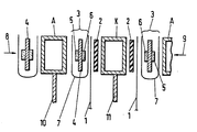
- the drawing shows a vertical section through the sealing area of a membrane electrolyzer, the parts being shown pulled apart.
- the frame of the anode A and also the cathode K consists of a square tube, but e.g. a round tube is also possible.
- a rubber seal (2) is located between the membrane (1) and the cathode compartment.
- the sealing part (3) between the membrane (1) and the anode tube consists of a flat core frame (4) made of asbestos, the two attached sealing frames (5,6) made of graphite and the foil cover (7) made of PTFE.
- the sealing frame (5) facing the anode A can also be dispensed with.
- the casing (7) ensures that the chlorine formed on the anode plates (10) does not destroy the sealing part (3).
- the hydrogen formed on the cathode plate (11) and the sodium hydroxide solution formed there are much less aggressive, so that the rubber seal (2) can be used in this area.
- the rubber seal (2) can also be replaced by a seal corresponding to the sealing part (3).
- the parts are shown pulled apart; they are pressed together in the direction of arrows (8) and (9).
- the graphite sealing frames (5, 6) ensure that no noteworthy forces act perpendicular to the contact pressure on the membrane (1) in the sealing area, which could damage the membrane.
- the rubber seal (2) on the one hand and the sealing part (3) on the other hand squeeze the membrane (1) in the sealing area so that no liquid can pass through the membrane to the outside.
- special graphite can preferably be used, which has a certain elasticity only in the direction of the arrows (8) and (9), but not perpendicular to it.
- the thickness of the graphite sealing frame (5,6) is usually in the range of 0.5 to 2 mm.
- the PTFE sleeve (7) is preferably 0.3 mm thick.
Landscapes
- Chemical & Material Sciences (AREA)
- Engineering & Computer Science (AREA)
- Chemical Kinetics & Catalysis (AREA)
- Electrochemistry (AREA)
- Materials Engineering (AREA)
- Metallurgy (AREA)
- Organic Chemistry (AREA)
- Electrolytic Production Of Non-Metals, Compounds, Apparatuses Therefor (AREA)
- Electrolytic Production Of Metals (AREA)
- Electrodes For Compound Or Non-Metal Manufacture (AREA)
- Sealing Material Composition (AREA)
- Sealing Devices (AREA)
Description
- Die Erfindung betrifft eine Dichtung für die aufeinandergepreßten Elektrodenrahmen einer Membranelektrolyse zur Erzeugung von Natronlauge, Wasserstoff und Chlor aus einer NaCI-Sole, wobei die Membran mit ihrem Rand zwischen der zweiteiligen Dichtung liegt.
- Die für diese Elektrolyse verwendete Membran hat im allgemeinen lonenaustauscheigenschaften, so daß neben dem durch die Membran wandernden Natrium auch Wasser hindurchtreten kann. Die Wassertransporteigenschaft der Membran hat zur Folge, daß bei der Abdichtung der Membranelektrolysevorrichtung Probleme auftreten können. Es muß insbesondere dafür gesorgt werden, daß kein Wasser durch die Schmalseite der Membran nach außen tritt. Um dies zu unterbinden, muß die Membran im Dichtungsbereich zusammengepreßt werden. Verwendet man auf beiden Seiten der Membran Gummidichtungen, so dehnen sich die Dichtungen unter dem Anpreßdruck parallel zur Membranfläche aus und führen durch diese Bewegung zu Beschädigungen oder Zerstörungen der Membran.
- Der Erfindung liegt die Aufgabe zugrunde, eine Dichtung zu finden, die senkrecht auf die Membran wirkende, ausreichend hohe Kräfte übertragen kann, ohne daß dabei aber eine solche Formänderung der Dichtung auftritt, welche große, parallel zur Membran wirkende Kräfte überträgt. Die Dichtung muß gleichzeitig auch gegen die in den Elektrolyseuren vorhandene Flüssigkeit beständig sein, da es sich hierbei um eine ungesättigte Kochsalzlösung handelt, die neben Chlorat und chloriger Säure bei einem pH-Wert von etwa 4,5 gelöstes und gasförmiges Chlor enthält. Erfindungsgemäß wird die Aufgabe dadurch gelöst, daß mindestens ein Dichtungsteil aus einem Kernrahmen und mindestens einseitig auf den Kernrahmen aufgesetztem Dichtungsrahmen aus Graphit besteht und der Kernrahmen und der Dichtungsrahmen mit einer Folienhülle aus Polytetrafluorethylen umgeben sind.
- Bei der erfindungsgemäßen Dichtung dient der Kernrahmen, der z.B. aus Asbest besteht, vor allem der besseren Handhabbarkeit des Dichtungsteils, da der Dichtungsrahmen aus Graphit üblicheweise dünn und schmal ausgebildet ist. Die Folienhülle sorgt für die Korrosionsbeständigkeit des Dichtungsteils.
- Zum Abdichten werden Preßdrücke im Bereich von 700 bis 2000 N/cm2 und vorzugsweise 900 bis 1500 N/cm2 angewandt. Bei diesen nicht allzu hohen Preßdrücken genügt es zumeist, nur ein Dichtungsteil der zweiteiligen, beiderseits der Membran befindlichen Dichtung in der erfindungsgemäßen Weise auszubilden und für das andere Dichtungsteil eine Gummidichtung zu verwenden. Der Dichtungsrahmen aus Graphit kann nämlich ziemlich schmal ausgebildet werden, so daß der Dichtungsbereich der Gummidichtung ebenfalls schmal ist und nicht nennenswert parallel zur Membranfläche verformt wird.
- Einzelheiten der Dichtung werden mit Hilfe der Zeichnung erläutert. Die Zeichnung zeigt 'einen senkrechten Schnitt durch den Dichtungsbereich eines Membranelektrolyseurs, wobei die Teile auseinandergezogen dargestellt sind.
- Der Rahmen der Anode A und auch der Kathode K besteht aus einem Vierkantrohr, doch ist z.B. auch ein Rundrohr möglich. Zwischen der Membran (1) und dem Kathodenraum befindet sich eine Gummidichtung (2). Der Dichtungsteil (3) zwischen der Membran (1) und dem Anodenrohr besteht aus einem flachen Kernrahmen (4) aus Asbest, den beiden aufgesetzten Dichtungsrahmen (5,6) aus Graphit und der Folienhülle (7) aus PTFE. Auf den der Anode A zugewandten Dichtungsrahmen (5) kann in manchen Fällen auch verzichtet werden. Die Hülle (7) sorgt dafür, daß das an den Anodenplatten (10) gebildete Chlor den Dichtungsteil (3) nicht zerstört. Der an der Kathodenplatte (11) gebildete Wasserstoff und auch die dort entstehende Natronlauge sind viel weniger aggressiv, so daß in diesem Bereich mit der Gummidichtung (2) gearbeitet werden kann. Die Gummidichtung (2) kann aber auch durch eine dem Dichtungsteil (3) entsprechende Dichtung ersetzt werden.
- In der Zeichnung sind die Teile auseinandergezogen dargestellt; sie werden im Betrieb in Richtung der Pfeile (8) und (9) zusammengepreßt. Die Graphitdichtungsrahmen (5,6) sorgen dafür, daß auf die Membran (1) im Dichtungsbereich keine nennenswerten Kräfte senkrecht zum Anpreßdruck wirken, welche zu Beschädigungen der Membran führen könnten. Durch die Gummidichtung (2) einerseits und das Dichtungsteil (3) andererseits wird die Membran (1) im Dichtungsbereich so abgequetscht, daß keine Flüssigkeit durch die Membran nach außen treten kann. Für die Dichtungsrahmen (5,6) aus Graphit kann man vorzugsweise speziellen Graphit verwenden, der nur in Richtung der Pfeile (8) und (9) eine gewisse Elastizität, jedoch nicht senkrecht dazu besitzt.
- Für den Kernrahmen (4) aus Asbest kann man z.B. eine Stärke von etwa 2 mm wählen, die Stärke der Graphitdichtungsrahmen (5,6) liegt zumeist im Bereich von 0,5 bis 2 mm. Die PTFE-Hülle (7) ist vorzugsweise 0,3 mm stark.
Claims (2)
Priority Applications (1)
| Application Number | Priority Date | Filing Date | Title |
|---|---|---|---|
| AT88200266T ATE57718T1 (de) | 1987-02-25 | 1988-02-13 | Dichtung fuer die elektrodenrahmen einer membranelektrolyse. |
Applications Claiming Priority (2)
| Application Number | Priority Date | Filing Date | Title |
|---|---|---|---|
| DE3705926A DE3705926C1 (de) | 1987-02-25 | 1987-02-25 | Dichtung fuer die Elektrodenrahmen einer Membranelektrolyse |
| DE3705926 | 1987-02-25 |
Publications (2)
| Publication Number | Publication Date |
|---|---|
| EP0280359A1 EP0280359A1 (de) | 1988-08-31 |
| EP0280359B1 true EP0280359B1 (de) | 1990-10-24 |
Family
ID=6321665
Family Applications (1)
| Application Number | Title | Priority Date | Filing Date |
|---|---|---|---|
| EP88200266A Expired - Lifetime EP0280359B1 (de) | 1987-02-25 | 1988-02-13 | Dichtung für die Elektrodenrahmen einer Membranelektrolyse |
Country Status (8)
| Country | Link |
|---|---|
| US (1) | US4776940A (de) |
| EP (1) | EP0280359B1 (de) |
| JP (1) | JPS63227795A (de) |
| AT (1) | ATE57718T1 (de) |
| AU (1) | AU1209988A (de) |
| BR (1) | BR8800766A (de) |
| DE (2) | DE3705926C1 (de) |
| ES (1) | ES2018333B3 (de) |
Families Citing this family (5)
| Publication number | Priority date | Publication date | Assignee | Title |
|---|---|---|---|---|
| US4940518A (en) * | 1988-09-26 | 1990-07-10 | The Dow Chemical Company | Combination seal member and membrane holder for a filter press type electrolytic cell |
| DE19750313A1 (de) * | 1997-11-13 | 1999-05-27 | Gore W L & Ass Gmbh | Elektrolysezellenanordnung und Verfahren zum Abdichten einer Elektrolysezelle |
| DE19750314A1 (de) * | 1997-11-13 | 1999-05-27 | Gore W L & Ass Gmbh | Elektrolysezellenanordnung und Verfahren zum Abdichten einer Elektrolysezelle |
| DE102004041043B3 (de) * | 2004-08-25 | 2006-03-30 | Klinger Ag | Laminiertes Dichtungsmaterial und Verfahren zu seiner Herstellung |
| CN102936736A (zh) * | 2012-11-19 | 2013-02-20 | 扬州中电制氢设备有限公司 | 包边隔膜垫片 |
Family Cites Families (10)
| Publication number | Priority date | Publication date | Assignee | Title |
|---|---|---|---|---|
| US3984304A (en) * | 1974-11-11 | 1976-10-05 | Ppg Industries, Inc. | Electrode unit |
| US4013535A (en) * | 1976-06-07 | 1977-03-22 | The B. F. Goodrich Company | Electrolyte separator tensioning device |
| US4217199A (en) * | 1979-07-10 | 1980-08-12 | Ppg Industries, Inc. | Electrolytic cell |
| US4332661A (en) * | 1980-11-05 | 1982-06-01 | Olin Corporation | Cells having gasket lubricating means |
| US4431502A (en) * | 1980-11-05 | 1984-02-14 | Olin Corporation | Sealing means for filter press cells |
| US4441977A (en) * | 1980-11-05 | 1984-04-10 | Olin Corporation | Electrolytic cell with sealing means |
| GB2098238B (en) * | 1981-05-07 | 1984-10-24 | Electricity Council | An electrochemical cell |
| US4344633A (en) * | 1981-05-22 | 1982-08-17 | Diamond Shamrock Corporation | Gasket for electrolytic cell |
| US4610765A (en) * | 1984-09-24 | 1986-09-09 | The Dow Chemical Company | Seal means for electrolytic cells |
| US4721555A (en) * | 1985-08-02 | 1988-01-26 | The Dow Chemical Company | Electrolysis cell seal means |
-
1987
- 1987-02-25 DE DE3705926A patent/DE3705926C1/de not_active Expired
-
1988
- 1988-02-13 AT AT88200266T patent/ATE57718T1/de not_active IP Right Cessation
- 1988-02-13 ES ES88200266T patent/ES2018333B3/es not_active Expired - Lifetime
- 1988-02-13 DE DE8888200266T patent/DE3860841D1/de not_active Expired - Lifetime
- 1988-02-13 EP EP88200266A patent/EP0280359B1/de not_active Expired - Lifetime
- 1988-02-16 US US07/156,370 patent/US4776940A/en not_active Expired - Fee Related
- 1988-02-24 BR BR8800766A patent/BR8800766A/pt unknown
- 1988-02-24 AU AU12099/88A patent/AU1209988A/en not_active Abandoned
- 1988-02-25 JP JP63043265A patent/JPS63227795A/ja active Pending
Also Published As
| Publication number | Publication date |
|---|---|
| BR8800766A (pt) | 1988-10-04 |
| ES2018333B3 (es) | 1991-04-01 |
| JPS63227795A (ja) | 1988-09-22 |
| DE3705926C1 (de) | 1988-08-18 |
| US4776940A (en) | 1988-10-11 |
| AU1209988A (en) | 1988-09-01 |
| ATE57718T1 (de) | 1990-11-15 |
| EP0280359A1 (de) | 1988-08-31 |
| DE3860841D1 (de) | 1990-11-29 |
Similar Documents
| Publication | Publication Date | Title |
|---|---|---|
| DE69902055T2 (de) | Hochdruck-elektrolyseeinheit | |
| DE2616614C2 (de) | Elektrolyseeinrichtung | |
| DE2646463A1 (de) | Plattenelektrode fuer eine elektrolysezelle | |
| DE2656650A1 (de) | Bipolare elektrode fuer eine elektrolysezelle | |
| DE2809332A1 (de) | Elektrolytische membranzelle | |
| DE102006020374A1 (de) | Mikrostrukturierter Isolierrahmen für Elektrolysezellen | |
| DE2735239A1 (de) | Elektrode | |
| DE2545328A1 (de) | Dichtung fuer eine elektrolytische zelle und verfahren zu ihrer herstellung | |
| DE1184329B (de) | Stabile, semipermeable, fuer Kationen selektiv durchlaessige Membran fuer Elektrolysezellen | |
| DE2855837C2 (de) | ||
| EP0280359B1 (de) | Dichtung für die Elektrodenrahmen einer Membranelektrolyse | |
| DE2222637A1 (de) | Halterahmen fuer elektroden von elektrolysevorrichtungen | |
| DE2856882A1 (de) | Vorrichtung zum elektrolysieren und verfahren zum herstellen von chlor durch elektrolysieren | |
| DE3420483A1 (de) | Bipolarer elektrolyseapparat mit gasdiffusionskathode | |
| DE3219704A1 (de) | Membran-elektrolysezelle | |
| DD250556A5 (de) | Monopolare zelle | |
| DE102012013832A1 (de) | Isolierrahmen mit Eckenkompensatoren für Elektrolysezellen | |
| DE69002545T2 (de) | Dichtungen für Filterpress-Typ-Zellen. | |
| DE2841148C2 (de) | ||
| DE1467067A1 (de) | Elektrolytische Zelle | |
| DE2923818A1 (de) | Elektrodenabteil | |
| DE2615118A1 (de) | Schutzueberzug fuer den rahmen von filterpressen-elektrolysezellen | |
| DE2821983A1 (de) | Dichtelement fuer membranen, insbesondere bei filterpressenartig angeordneten elektrolysezellen | |
| DD270934A5 (de) | Elektrolytische zelle | |
| DD152148A5 (de) | Plattieren von kathoden in einer elektrolytischen zelle!mit diaphragma oder membran |
Legal Events
| Date | Code | Title | Description |
|---|---|---|---|
| PUAI | Public reference made under article 153(3) epc to a published international application that has entered the european phase |
Free format text: ORIGINAL CODE: 0009012 |
|
| AK | Designated contracting states |
Kind code of ref document: A1 Designated state(s): AT BE CH DE ES FR GB IT LI SE |
|
| 17P | Request for examination filed |
Effective date: 19880928 |
|
| 17Q | First examination report despatched |
Effective date: 19891208 |
|
| GRAA | (expected) grant |
Free format text: ORIGINAL CODE: 0009210 |
|
| AK | Designated contracting states |
Kind code of ref document: B1 Designated state(s): AT BE CH DE ES IT LI |
|
| REF | Corresponds to: |
Ref document number: 57718 Country of ref document: AT Date of ref document: 19901115 Kind code of ref document: T |
|
| REF | Corresponds to: |
Ref document number: 3860841 Country of ref document: DE Date of ref document: 19901129 |
|
| ITF | It: translation for a ep patent filed | ||
| EN | Fr: translation not filed | ||
| PLBE | No opposition filed within time limit |
Free format text: ORIGINAL CODE: 0009261 |
|
| STAA | Information on the status of an ep patent application or granted ep patent |
Free format text: STATUS: NO OPPOSITION FILED WITHIN TIME LIMIT |
|
| 26N | No opposition filed | ||
| ITTA | It: last paid annual fee | ||
| PGFP | Annual fee paid to national office [announced via postgrant information from national office to epo] |
Ref country code: DE Payment date: 19940311 Year of fee payment: 7 |
|
| PGFP | Annual fee paid to national office [announced via postgrant information from national office to epo] |
Ref country code: AT Payment date: 19941216 Year of fee payment: 8 |
|
| PGFP | Annual fee paid to national office [announced via postgrant information from national office to epo] |
Ref country code: BE Payment date: 19950227 Year of fee payment: 8 |
|
| PGFP | Annual fee paid to national office [announced via postgrant information from national office to epo] |
Ref country code: ES Payment date: 19950228 Year of fee payment: 8 |
|
| PGFP | Annual fee paid to national office [announced via postgrant information from national office to epo] |
Ref country code: CH Payment date: 19950317 Year of fee payment: 8 |
|
| PG25 | Lapsed in a contracting state [announced via postgrant information from national office to epo] |
Ref country code: DE Effective date: 19951101 |
|
| PG25 | Lapsed in a contracting state [announced via postgrant information from national office to epo] |
Ref country code: AT Effective date: 19960213 |
|
| PG25 | Lapsed in a contracting state [announced via postgrant information from national office to epo] |
Ref country code: ES Free format text: LAPSE BECAUSE OF NON-PAYMENT OF DUE FEES Effective date: 19960214 |
|
| PG25 | Lapsed in a contracting state [announced via postgrant information from national office to epo] |
Ref country code: BE Effective date: 19960228 |
|
| PG25 | Lapsed in a contracting state [announced via postgrant information from national office to epo] |
Ref country code: LI Effective date: 19960229 Ref country code: CH Effective date: 19960229 |
|
| BERE | Be: lapsed |
Owner name: METALLGESELLSCHAFT A.G. Effective date: 19960228 |
|
| REG | Reference to a national code |
Ref country code: CH Ref legal event code: PL |
|
| REG | Reference to a national code |
Ref country code: ES Ref legal event code: FD2A Effective date: 19990405 |
|
| PG25 | Lapsed in a contracting state [announced via postgrant information from national office to epo] |
Ref country code: IT Free format text: LAPSE BECAUSE OF NON-PAYMENT OF DUE FEES;WARNING: LAPSES OF ITALIAN PATENTS WITH EFFECTIVE DATE BEFORE 2007 MAY HAVE OCCURRED AT ANY TIME BEFORE 2007. THE CORRECT EFFECTIVE DATE MAY BE DIFFERENT FROM THE ONE RECORDED. Effective date: 20050213 |