EP0279533B1 - Kraftfahrzeugrad - Google Patents
Kraftfahrzeugrad Download PDFInfo
- Publication number
- EP0279533B1 EP0279533B1 EP88300681A EP88300681A EP0279533B1 EP 0279533 B1 EP0279533 B1 EP 0279533B1 EP 88300681 A EP88300681 A EP 88300681A EP 88300681 A EP88300681 A EP 88300681A EP 0279533 B1 EP0279533 B1 EP 0279533B1
- Authority
- EP
- European Patent Office
- Prior art keywords
- rim
- vehicle wheel
- clamping
- accordance
- support rings
- Prior art date
- Legal status (The legal status is an assumption and is not a legal conclusion. Google has not performed a legal analysis and makes no representation as to the accuracy of the status listed.)
- Expired - Lifetime
Links
Images

Classifications
-
- B—PERFORMING OPERATIONS; TRANSPORTING
- B60—VEHICLES IN GENERAL
- B60C—VEHICLE TYRES; TYRE INFLATION; TYRE CHANGING; CONNECTING VALVES TO INFLATABLE ELASTIC BODIES IN GENERAL; DEVICES OR ARRANGEMENTS RELATED TO TYRES
- B60C17/00—Tyres characterised by means enabling restricted operation in damaged or deflated condition; Accessories therefor
- B60C17/04—Tyres characterised by means enabling restricted operation in damaged or deflated condition; Accessories therefor utilising additional non-inflatable supports which become load-supporting in emergency
- B60C17/06—Tyres characterised by means enabling restricted operation in damaged or deflated condition; Accessories therefor utilising additional non-inflatable supports which become load-supporting in emergency resilient
-
- B—PERFORMING OPERATIONS; TRANSPORTING
- B60—VEHICLES IN GENERAL
- B60B—VEHICLE WHEELS; CASTORS; AXLES FOR WHEELS OR CASTORS; INCREASING WHEEL ADHESION
- B60B21/00—Rims
- B60B21/12—Appurtenances, e.g. lining bands
-
- B—PERFORMING OPERATIONS; TRANSPORTING
- B60—VEHICLES IN GENERAL
- B60C—VEHICLE TYRES; TYRE INFLATION; TYRE CHANGING; CONNECTING VALVES TO INFLATABLE ELASTIC BODIES IN GENERAL; DEVICES OR ARRANGEMENTS RELATED TO TYRES
- B60C17/00—Tyres characterised by means enabling restricted operation in damaged or deflated condition; Accessories therefor
- B60C17/04—Tyres characterised by means enabling restricted operation in damaged or deflated condition; Accessories therefor utilising additional non-inflatable supports which become load-supporting in emergency
- B60C17/041—Tyres characterised by means enabling restricted operation in damaged or deflated condition; Accessories therefor utilising additional non-inflatable supports which become load-supporting in emergency characterised by coupling or locking means between rim and support
- B60C17/042—Tyres characterised by means enabling restricted operation in damaged or deflated condition; Accessories therefor utilising additional non-inflatable supports which become load-supporting in emergency characterised by coupling or locking means between rim and support preventing sliding or rotation between support and rim
Definitions
- the invention relates to a vehicle wheel comprising a multi-part rim having bead seats and lateral rim flanges, a tubeless pneumatic tyre, in particular a radial tyre and also an emergency running system which is arranged on the trim between and in contact with the tyre beads.
- the emergency running ring for this known vehicle wheel consists of rubber or other elastomeric material, is of one piece construction and sits with its foot part, which fully fills out the space between the tyre beads, on a flat base rim with an inclined shoulder.
- the emergency running ring takes on a supporting function on the one hand and prevents, on the other hand, the tyre beads from moving off the bead seats, and the vehicle thereby loosing its directional stability and steerability.
- Vehicle wheels with metallic emergency running rings are also known, wherein the emergency running rings consist of several segments and are pressed against the base of the rim, with the segments being clamped relative to one another.
- the object underlying the present invention is thus to provide a vehicle wheel of the initially named kind which the special feature that the installation is made substantially easier with a simultaneous minimisation of weight, and above all to provide troublefree torque transmission between the rim and the emergency running ring.
- the installation is, on the one hand, made decisively easier and can be carried out by means of the customary tools which are carried on board the vehicle.
- a compact assembly is provided between the rim, the tyre beads and the emergency running system by means of the clamping and spreading segments which are anchored to the rim has by means of securing elements.
- the outer peripheral surface of the clamping and spreading segments which form a composite ring in the installed state, is provided with a gripping profile, so that when the tread is a torn away and the terrain is difficult the drive power which is available can still be used as effectively as possible.
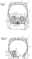
- the tyre 1 is mounted on a rim 5, which is a multi-part rim having the customary bead seats and lateral rim flanges 6.
- a wheel rim consisting of three segments is preferably used as the multi-part rim, however, in principle other desired multi-part rims can also be used, for example rims in which a rim flange or rim horn is formed as a separate part and is attached by screw means.
- An emergency running ring is mounted inside the pneumatic tyre 1 and consists of two rubber support rings 7, 8 and a wedge ring formed from metal clamping and spreading segments 9 attached centrally between the two support rings 7, 8.
- the clamping and spreading segments 9 have a wedge-shape in cross-section to press the support rings 7, 8 which consist of elastomeric rubber material, and optionally have internal reinforcement with a high contact force against the tyre beads 4 when the clamping and spreading segments are clamped against the rim 5 by means of the securing screws 10.
- This clamping together of the rim 5, beads 4, support rings 7,8 and the clamping and spreading segments 9 provides, in conjunction with the securing screws 10 which bring a direct force transmitting connection between the rim 5 and the clamping and spreading segments 9, a compact assembly which on the one hand can withstand all the loads which occur in emergency running situations, and also all external effects, to ensure an undisturbed torque transmission between the rim and emergency running system in all situations.
- the support rings 7, 8 are preferably provided with a soft elastic surface layer in the bead contacting region and the wheel rim base contacting region.
- This layer may for example be vulcanised into place, and advantageously contributes to the sealing of the pneumatic tyre and wheel assembly to allow use of a tubeless tyre.
- a sealing lip 14 expediently extends axially inwardly from each support ring 7, 8, with two sealing lips of the support rings 7, 8 overlapping each other and being pressed against the base of the rim by the clamping and spreading segments so that the required seal is ensured, even for rims which are built up from segments.
- One of the securing screws 10 is preferably simultaneously constructed and used as the valve for supplying inflation air to the tyre.
- the clamping and spreading segments In the radially outer region the clamping and spreading segments have centering projections 15 at both sides, which can also be realised by a throughgoing element which projects at both sides.
- centering projections 15 engage in guide grooves 16 which are formed in the support rings 7, 8 or vice versa.
- the support rings 7, 8 are furthermore each provided with a peripheral retaining projection 17 for the clamping and spreading segments 9. (See Figs 2 & 6)
- the vehicle wheel of the invention is above all characterised by its simple installation.
- known vehicle wheels of this kind which are equipped with emergency running rings require tyre installation presses and often also special tools
- the vehicle wheel of the invention with emergency running ring can be installed without special presses and the like solely using tools available on board the vehicle.
- field installation is also possible.
- Fig. 2 shows the pneumatic tyre 1 into which the first support ring 7 has already been introduced.
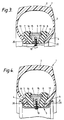
- Fig.3 shows the support rings 7, 8 and the clamping and spreading segments 9 inserted into the tyre 2.
- the tyre beads 4 are spread apart with the aid of a spreader so that sufficient space is available for the insertion and alignment of the spreading segments 9.
- this phase of the installation alignment of the clamping and spreading segments 9 relative to the support rings 7, 8 already occurs in that the centering projections 15 are disposed in the guide grooves 16 of the support rings 7, 8 so it is no longer possible for the segments 9 to fall back because of the retaining projections 17.
- This initial position makes later clamping possible.
- the installation of the multi-part rim can then take place.
- Fig.4 shows the state of the vehicle wheel after the removal of the holding bolts 18 and the installation of the multi-part rim 5, and also the screwing together of the latter with the clamping and spreading segments 9.
- stiffening ribs 19 which are provided above the rim flange region on the support rings 7, 8 at the tyre wall side are directly pressed against the inner wall of the tyre in the transition region from the bead to the sidewall. This results in an important stabilisation of the emergency running system in the radially outer region, which is very advantageous in the emergency running case.
- Channels 20 which are formed in the support rings 7, 8 facing the beads 4, and which preferably extend circumferentially, allow favourable volume compensation to be achieved during axial clamping.
- Fig.5. shows once again in schematic manner the process of axial clamping by means of the securing screws 10 which extend in the radial direction, with the right hand side of this representation showing the loose assembly between the clamping and spreading segments 9, the support ring 8, the bead 4 and the rim flange 6, whereas the final tensioned compact assembly of these elements is shown in the left hand part.
- This seal at the rim base is achieved by means of a continuous one-piece band which preferably extends over the entire rim width.
- sealing strips 21, 22 are preferably moulded onto the support rings 7, 8 and extend beneath the tyre beads 4 up to the rim flanges 6.
- Sealing strips 14 are likewise moulded onto the support rings 7, 8 and point towards the centre of the rim, with these sealing strips overlapping each other and being disposed between the rim base and the clamping and spreading segments 9.
Landscapes
- Engineering & Computer Science (AREA)
- Mechanical Engineering (AREA)
- Tires In General (AREA)
Claims (18)
Applications Claiming Priority (2)
| Application Number | Priority Date | Filing Date | Title |
|---|---|---|---|
| DE19873704830 DE3704830A1 (de) | 1987-02-16 | 1987-02-16 | Fahrzeugrad |
| DE3704830 | 1987-02-16 |
Publications (3)
| Publication Number | Publication Date |
|---|---|
| EP0279533A2 EP0279533A2 (de) | 1988-08-24 |
| EP0279533A3 EP0279533A3 (en) | 1990-02-28 |
| EP0279533B1 true EP0279533B1 (de) | 1992-03-11 |
Family
ID=6321073
Family Applications (1)
| Application Number | Title | Priority Date | Filing Date |
|---|---|---|---|
| EP88300681A Expired - Lifetime EP0279533B1 (de) | 1987-02-16 | 1988-01-27 | Kraftfahrzeugrad |
Country Status (3)
| Country | Link |
|---|---|
| EP (1) | EP0279533B1 (de) |
| JP (1) | JPS63255106A (de) |
| DE (2) | DE3704830A1 (de) |
Families Citing this family (10)
| Publication number | Priority date | Publication date | Assignee | Title |
|---|---|---|---|---|
| GB9104484D0 (en) * | 1991-03-04 | 1991-04-17 | Luest Richard | Tyre-retention device and wheel rim |
| JP4633946B2 (ja) * | 2001-02-13 | 2011-02-16 | 不二精工株式会社 | ランフラットタイヤとリムとの組立体 |
| DE10132411A1 (de) * | 2001-07-04 | 2003-02-06 | Continental Ag | Anordnung für einen schlauchlosen, auf einer mehrteiligen Felge montierten Fahrzeugluftreifen |
| US20030116245A1 (en) * | 2001-12-20 | 2003-06-26 | Hsu Shut Chen | Tire breaker and anti-knock arrangement |
| FR2843335A1 (fr) * | 2002-10-17 | 2004-02-13 | Jean Gergele | Dispositif de securite pour les pneumatiques montes sur des jantes monobloc a gorge de montage. |
| TW593000B (en) * | 2002-12-19 | 2004-06-21 | Shuei-Jen Shiu | Effectiveness-improving device for preventing piercing through and explosion of tire |
| GB0702156D0 (en) * | 2007-02-05 | 2007-03-14 | Lust Richard | Method and system for fitting a runflat assembly |
| FR2913917B1 (fr) * | 2007-03-23 | 2011-04-29 | Hutchinson | Dispositif de roulage a plat pour vehicule automobile et ensemble monte l'incorporant |
| CN101885294A (zh) * | 2010-07-08 | 2010-11-17 | 陈桂宝 | 内置式爆胎安全器 |
| DE102016122164B4 (de) | 2016-11-17 | 2018-09-06 | Krauss-Maffei Wegmann Gmbh & Co. Kg | Notlaufring |
Family Cites Families (6)
| Publication number | Priority date | Publication date | Assignee | Title |
|---|---|---|---|---|
| DE1755180A1 (de) * | 1968-04-09 | 1971-12-02 | Franz Cromm | Befestigung eines Notlauf-Stuetzringes im schlauchlosen Reifen bei Fahrzeugraedern jeder Art |
| DE1908204C3 (de) * | 1969-02-19 | 1975-09-25 | Daimler-Benz Ag, 7000 Stuttgart | Notlaufring für schlauchlose Fahrzeugbereifungen |
| JPS5123902B1 (de) * | 1969-12-30 | 1976-07-20 | ||
| JPS5043A (de) * | 1973-05-02 | 1975-01-06 | ||
| SE418481B (sv) * | 1974-03-11 | 1981-06-09 | Trelleborgs Gummifabriks Ab | Anordning vid felg for fordonshjul |
| GB1572041A (en) * | 1976-03-25 | 1980-07-23 | Ford Motor Co | Runflat system for a vehicle wheel |
-
1987
- 1987-02-16 DE DE19873704830 patent/DE3704830A1/de not_active Withdrawn
-
1988
- 1988-01-27 DE DE8888300681T patent/DE3868951D1/de not_active Expired - Fee Related
- 1988-01-27 EP EP88300681A patent/EP0279533B1/de not_active Expired - Lifetime
- 1988-02-16 JP JP63033060A patent/JPS63255106A/ja active Pending
Also Published As
| Publication number | Publication date |
|---|---|
| JPS63255106A (ja) | 1988-10-21 |
| DE3704830A1 (de) | 1988-08-25 |
| EP0279533A3 (en) | 1990-02-28 |
| EP0279533A2 (de) | 1988-08-24 |
| DE3868951D1 (de) | 1992-04-16 |
Similar Documents
| Publication | Publication Date | Title |
|---|---|---|
| AU2005202095B2 (en) | Solid rubber tire with flexible hub and replaceable tire tread | |
| US6672349B1 (en) | Vehicle wheel with a pneumatic tire | |
| US4008743A (en) | Pneumatic tire with puncture resistance internal safety structure | |
| US7946324B2 (en) | Run flat device for a motor vehicle, and a wheel assembly incorporating it | |
| EP0279533B1 (de) | Kraftfahrzeugrad | |
| US4823854A (en) | Safety tire and rim combination with safety insert | |
| US7398809B2 (en) | Run flat tire insert system | |
| US20070261774A1 (en) | Tyre for Vehicles, in Particular Motor Vehicles | |
| US4658876A (en) | Automotive vehicle tire and mounting system therefor | |
| JP2003502212A (ja) | タイヤ、リムおよびアダプタからなる組立体 | |
| US3877503A (en) | Method for anchoring a pneumatic tire to the rim and pneumatic wheel so obtained | |
| US4401144A (en) | Wheel rims for pneumatic tires | |
| US20080073017A1 (en) | Run-flat system comprising a foam support ring mounted to a rim by securing strips | |
| US4071068A (en) | Removable track belt with removable keeper bar | |
| US4408647A (en) | Vehicle wheel | |
| US5593520A (en) | Ring device for running on a flat tire | |
| CA1237056A (en) | Vehicle wheel | |
| US6109319A (en) | Run-flat support for pneumatic tired wheel | |
| US7575030B2 (en) | Runflat device for a motor vehicle, and a mounted assembly incorporating it | |
| JPH04228310A (ja) | 複タイヤ・リム・アセンブリと複リム・アセンブリ のガッタ・バンド縁部の金属疲労を減らす方法 | |
| US4108228A (en) | Vehicle wheel with rubber tire | |
| US4306603A (en) | Vehicle tire with tractive elements | |
| EP0125047A1 (de) | Fahrzeugreifen und Montageverfahren | |
| US4953291A (en) | Tire interior support system | |
| JPH0253241B2 (de) |
Legal Events
| Date | Code | Title | Description |
|---|---|---|---|
| PUAI | Public reference made under article 153(3) epc to a published international application that has entered the european phase |
Free format text: ORIGINAL CODE: 0009012 |
|
| AK | Designated contracting states |
Kind code of ref document: A2 Designated state(s): DE FR GB IT |
|
| PUAL | Search report despatched |
Free format text: ORIGINAL CODE: 0009013 |
|
| AK | Designated contracting states |
Kind code of ref document: A3 Designated state(s): DE FR GB IT |
|
| 17P | Request for examination filed |
Effective date: 19900216 |
|
| 17Q | First examination report despatched |
Effective date: 19910806 |
|
| GRAA | (expected) grant |
Free format text: ORIGINAL CODE: 0009210 |
|
| AK | Designated contracting states |
Kind code of ref document: B1 Designated state(s): DE FR GB IT |
|
| ITF | It: translation for a ep patent filed | ||
| REF | Corresponds to: |
Ref document number: 3868951 Country of ref document: DE Date of ref document: 19920416 |
|
| ET | Fr: translation filed | ||
| PLBE | No opposition filed within time limit |
Free format text: ORIGINAL CODE: 0009261 |
|
| STAA | Information on the status of an ep patent application or granted ep patent |
Free format text: STATUS: NO OPPOSITION FILED WITHIN TIME LIMIT |
|
| 26N | No opposition filed | ||
| PGFP | Annual fee paid to national office [announced via postgrant information from national office to epo] |
Ref country code: GB Payment date: 19941130 Year of fee payment: 8 |
|
| PGFP | Annual fee paid to national office [announced via postgrant information from national office to epo] |
Ref country code: FR Payment date: 19950130 Year of fee payment: 8 |
|
| PGFP | Annual fee paid to national office [announced via postgrant information from national office to epo] |
Ref country code: DE Payment date: 19950313 Year of fee payment: 8 |
|
| PG25 | Lapsed in a contracting state [announced via postgrant information from national office to epo] |
Ref country code: GB Effective date: 19960127 |
|
| GBPC | Gb: european patent ceased through non-payment of renewal fee |
Effective date: 19960127 |
|
| PG25 | Lapsed in a contracting state [announced via postgrant information from national office to epo] |
Ref country code: FR Effective date: 19960930 |
|
| PG25 | Lapsed in a contracting state [announced via postgrant information from national office to epo] |
Ref country code: DE Effective date: 19961001 |
|
| REG | Reference to a national code |
Ref country code: FR Ref legal event code: ST |
|
| PG25 | Lapsed in a contracting state [announced via postgrant information from national office to epo] |
Ref country code: IT Free format text: LAPSE BECAUSE OF NON-PAYMENT OF DUE FEES;WARNING: LAPSES OF ITALIAN PATENTS WITH EFFECTIVE DATE BEFORE 2007 MAY HAVE OCCURRED AT ANY TIME BEFORE 2007. THE CORRECT EFFECTIVE DATE MAY BE DIFFERENT FROM THE ONE RECORDED. Effective date: 20050127 |