EP0279132B1 - Vorrichtung zur Feststellung der Lage einer Vielzahl von Magnetköpfen - Google Patents
Vorrichtung zur Feststellung der Lage einer Vielzahl von Magnetköpfen Download PDFInfo
- Publication number
- EP0279132B1 EP0279132B1 EP87402849A EP87402849A EP0279132B1 EP 0279132 B1 EP0279132 B1 EP 0279132B1 EP 87402849 A EP87402849 A EP 87402849A EP 87402849 A EP87402849 A EP 87402849A EP 0279132 B1 EP0279132 B1 EP 0279132B1
- Authority
- EP
- European Patent Office
- Prior art keywords
- head
- signal
- support
- circuit
- drum
- Prior art date
- Legal status (The legal status is an assumption and is not a legal conclusion. Google has not performed a legal analysis and makes no representation as to the accuracy of the status listed.)
- Expired - Lifetime
Links
Images


Classifications
-
- G—PHYSICS
- G11—INFORMATION STORAGE
- G11B—INFORMATION STORAGE BASED ON RELATIVE MOVEMENT BETWEEN RECORD CARRIER AND TRANSDUCER
- G11B21/00—Head arrangements not specific to the method of recording or reproducing
- G11B21/02—Driving or moving of heads
- G11B21/08—Track changing or selecting during transducing operation
- G11B21/081—Access to indexed tracks or parts of continuous track
- G11B21/086—Access to indexed tracks or parts of continuous track on tapes
-
- G—PHYSICS
- G11—INFORMATION STORAGE
- G11B—INFORMATION STORAGE BASED ON RELATIVE MOVEMENT BETWEEN RECORD CARRIER AND TRANSDUCER
- G11B5/00—Recording by magnetisation or demagnetisation of a record carrier; Reproducing by magnetic means; Record carriers therefor
- G11B5/48—Disposition or mounting of heads or head supports relative to record carriers ; arrangements of heads, e.g. for scanning the record carrier to increase the relative speed
- G11B5/58—Disposition or mounting of heads or head supports relative to record carriers ; arrangements of heads, e.g. for scanning the record carrier to increase the relative speed with provision for moving the head for the purpose of maintaining alignment of the head relative to the record carrier during transducing operation, e.g. to compensate for surface irregularities of the latter or for track following
- G11B5/584—Disposition or mounting of heads or head supports relative to record carriers ; arrangements of heads, e.g. for scanning the record carrier to increase the relative speed with provision for moving the head for the purpose of maintaining alignment of the head relative to the record carrier during transducing operation, e.g. to compensate for surface irregularities of the latter or for track following for track following on tapes
- G11B5/588—Disposition or mounting of heads or head supports relative to record carriers ; arrangements of heads, e.g. for scanning the record carrier to increase the relative speed with provision for moving the head for the purpose of maintaining alignment of the head relative to the record carrier during transducing operation, e.g. to compensate for surface irregularities of the latter or for track following for track following on tapes by controlling the position of the rotating heads
- G11B5/592—Disposition or mounting of heads or head supports relative to record carriers ; arrangements of heads, e.g. for scanning the record carrier to increase the relative speed with provision for moving the head for the purpose of maintaining alignment of the head relative to the record carrier during transducing operation, e.g. to compensate for surface irregularities of the latter or for track following for track following on tapes by controlling the position of the rotating heads using bimorph elements supporting the heads
Definitions
- the present invention relates to a device for detecting the position of a recording / reading head, for example magnetic, and finds application in the field of apparatus for recording and / or reading information by a head in front which scrolls an information carrier tape, such as a magnetic tape.
- recording / playback devices of known type called "with rotating heads", in which the tape is wound helically according to an ⁇ or an ⁇ (in top view) around a cylindrical drum comprising a slot median arranged in an equatorial plane and inside which rotates a disc-shaped element carrying on its periphery a set of magnetic heads, slightly protruding from the wall of the drum; the displacement of the rotating heads and of the tape in translation means that the information is arranged on the tape along segments of parallel tracks, inclined with respect to the longitudinal axis of the tape.
- the inclination of the tracks on the strip is a function of the relative head / strip speed.
- the information recorded on the tape must therefore be read with the same relative speed as the recording, failing which the heads no longer follow the tracks which are arranged on the tape at a normalized constant inclination.
- the tape speed and / or the speed of rotation of the heads, and / or the axial position of the head relative to the tape are varied on both sides of the equatorial plane of rotation of the rotating disc.
- the axial displacement of the head in order to place it in a given position relative to the strip requires knowing at all times and in a precise manner, the effective position of the head, in order to subject the means to the real position movement of the head, consisting for example of a recessed piezoelectric bimetallic strip and whose free end carries the head.
- strain gauges arranged on a piezoelectric plate carrying the head, to detect and measure the deformation thereof, and therefore the position of the head.
- This device is relatively complex to carry out given the difficulty of having gauges on the blades.
- This device has a relatively large size, and requires to provide a relatively high height of the rotating disc, with the difficulties and mechanical stresses which result therefrom.
- the French patent application No. 2427660 discloses a device for controlling the position of a piezoelectric element taking into account the effect of the hysteresis, comprising an oscillating arm wherein said element is used itself as capacity.
- This known device is relatively complex having regard to the necessary electronic circuit.
- This known embodiment results in a complex construction of the bimetallic strip.
- the French patent application No. 2,344,912 shows a device providing alignment correction between the main head recording / reproducing and the tracks on the tape, with two lateral detector heads, arranged on either side the main head on the same piezoelectric bimetallic strip; the difference in amplitudes of the signals detected by these side heads provides an indication of the position of the main head relative to the tracks.
- This prior device requires the addition of two magnetic heads, which not only increases the cost, but above all leads to assembly difficulties and a large size.
- US Pat. No. 4,183,060 describes an optical disc recording / playback apparatus of the video type, comprising a capacitive probe, the first electrode of which is integral with a lens which it is desired to maintain at a constant distance of the disc carrying the second electrode, despite the axial displacements of the surface of the disc when the latter is rotating; two resonant circuits are provided, the sum of the output signals of which provides a position error signal.
- the respective devices differ in particular by the nature of the information medium, namely on the one hand a flexible strip, not disposed in a plane, and on which the information is carried by tracks that are mechanically immaterializable, and the on the other side a flat rigid disc on which the information can be identified by the groove.
- the present invention overcomes the aforementioned drawbacks of the prior art and proposes a device detection of reduced dimensions and simple design.
- the device for detecting the position of a plurality of rotating heads comprises the elements described in claim 1.
- the device according to the invention provides, in a simple and space-saving manner, a measurement of the axial displacements of the rotating heads; moreover, the measurement is absolute.
- the support is formed of a piezoelectric bimetallic strip, one face of which constitutes the movable armature of the variable capacitor.
- a synchronous demodulation in amplitude of a signal is carried out.
- the fixed frame consists of an annular metal layer, coaxial with the drum, and arranged on one of the lower or upper faces of the slot, and facing the path of the rotating support.
- the generator generates as many detection signals of different frequencies as there are head supports (such as piezoelectric bimetals) and each applied to a respective support, the demodulation means comprising a circuit demodulation for each support.
- head supports such as piezoelectric bimetals
- the demodulation means comprising a circuit demodulation for each support.
- the generator generates a carrier signal of given frequency and is connected to the fixed armature, the demodulation means comprising as many demodulation circuits as there are supports.
- the means for measurement include a frequency multiplexing circuit making it possible to transmit, via the means of transmission of the deflection signal, in one direction the deflection signal towards the support, and in the opposite direction the output signal from the movable armature and containing the position information of the latter to the corresponding demodulation circuit.
- This variant is very simple, both mechanically and electronically.
- each demodulation circuit comprises an amplifier connected to an input of a multiplier, the other input of which receives the carrier input signal and the output of which drives a low-pass filter itself connected to an inverter.
- the measurement means comprise a 90 ° phase shift circuit to which the carrier input signal or the modulated output signal is applied.
- the device comprises a correction circuit, comprising a reference capacity placed in the vicinity of the variable measurement capacity, said circuit being connected to said measurement means so as to deliver a correctioin signal applied to these.
- the device according to the invention is incorporated in a servo circuit connecting the control means and the head support.
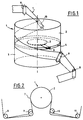
- the device of the present invention is described below in relation to an example of application to the field of recording / reading apparatuses with rotating magnetic heads, of the type known per se and as shown diagrammatically in FIGS. 1 and 2.
- a cylindrical drum 1 comprises an upper 2 and lower 3 part separated by a slot 4 substantially disposed in an equatorial plane perpendicular to the axis of the drum and halfway up the latter.
- a disc-shaped element 5 capable of being rotated around the axis of the drum; the disc carries one and generally several magnetic heads 6 arranged regularly on its periphery and projecting very slightly from the surface defining the wall of the drum.
- a magnetic strip 7 is capable of being wound helically around the drum 1, to form, in top view as shown in FIG. 2, a ⁇ .
- a set of rollers 8 to 11 guide the strip 7 and maintain it according to this configuration during its travel, from a supply reel to a take-up reel (not shown and known in themselves). The information is recorded / read on the tape in segments of tracks parallel and oblique to the axis of the tape.
- FIGS. 3 and 4 are diagrammatically represented two embodiments of the invention, in which similar elements bear the same reference of a figure to another. Only the lower part 3 of the drum 1 is shown for clarity.
- a disc-shaped element 5 carrying a plurality of elongated supports 13, 14, 15 arranged radially and angularly distributed ( preferably on a regular basis).
- the device comprises for example six or eight supports, of which only the supports 13, 14, and 15 are visible in FIGS. 3 and 4.
- Each support is provided at its free end, that is to say the distal end by relative to the axis 12, of a lug respectively 16, 17, 18.
- On each lug is fixed a magnetic head respectively 19, 20 and 21 so that these protrude slightly radially relative to the outer surface of the drum , in order to come into contact with the strip wound on the drum.
- one support is provided per head.
- the magnetic heads are capable of being displaced in an axial direction, transverse to their plane of rotation and transversely to the axis of the strip (that is to say parallel to the axis 12 of the drum) and symbolized by the arrow f, in order to follow the inclined parallel tracks carrying the information on the strip.
- each support consists of a piezoelectric bimetallic strip.
- Each bimetallic strip (as shown in FIG. 5) comprises three parallel conductive layers 22, 23, 24 separated in pairs by a strip 25, 26 in piezoelectric material; the central layer 23 is connected to ground by an impedance Z, while the upper and lower layers 22, 24 are connected together and receive a deflection signal, so that the superimposed lamellas undergo, under the effect of said signal, respectively an elongation and a shortening, causing the bending of the bimetallic strip.
- Each bimetallic strip receives a deflection signal, generated by control means 27, and transmitted in a known manner to said bimetallic strip by means of a transmission assembly 28 comprising rotating contacts 29 (in number equal to the number of bimetallic strips plus one) , a connection circuit 30, and high voltage amplifiers 31.
- the deflection signals can have a frequency of the order of 60 to 500 Hz and an amplitude of 100 to 200 Volts.
- the device according to the invention comprises, for each bimetallic strip, a position sensor with variable capacity provided with a frame movable relative to a fixed frame, constituting a reference for the detection of the axial position of the bimetallic strip.
- the movable armature is formed by the piezoelectric bimetal itself, and more precisely by one of the external metallic faces of the latter, while the fixed armature 32 is constituted by an annular planar conductive layer, centered on the axis 5 of the drum, and disposed on one of the lower or upper straight sections of the drum facing the slot 4 (see Figures 3 and 4).
- the bimetallic strips 13, 14 and 15 are always opposite the annular conductive layer 32 constituting the fixed armature.
- any axial deflection of a bimetallic strip causes its separation or its approximation of the fixed annular armature 32, and therefore modifies the variable measurement capacity C m formed by these frames.
- the fixed frame 32 is common to all the variable capacities C m formed by the combination of bimetallic strip / fixed frame.
- the annular layer 32 is arranged on the lower cross section of the drum facing the slot; it is therefore located opposite the conductive underside of each bimetallic strip; alternatively, the annular layer 32 can be fixed on the upper straight section of the drum, so as to be arranged above the bimetallic strips.
- each variable capacity sensor in other words with each bimetallic strip / fixed armature, and intended to allow the measurement of the measurement capacity C m thus formed.
- the device according to the invention is based on the principle of measuring the amplitude of an amplitude-modulated signal, subjected to a synchronous demodulation, in order to reduce the influence of spurious signals.
- An alternative input signal called a detection signal as opposed to the deflection signal, and also called hereinafter a carrier input signal, is injected into one of the reinforcements.
- An alternating electrical input signal is applied to an armature of the measurement capacitance and a modulated output signal is received on the other armature, said other armature being connected to ground by a resistive impedance called Z.
- Each capacitance Cm consists of a bimetallic strip and the fixed reference frame 32.
- the measurement means comprise a generator 33 generating a carrier input signal applied to one of the armatures, and demodulation means 34 receiving on an input the carrier input signal and whose other input receives the modulated output signal from the other frame.
- each final signal is applied to the control means 27 in order to produce a feedback loop, as shown on Figure 10.
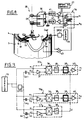
- FIGS. 3 and 4 show two respective embodiments whose specific features are described below.
- the generator 33 In the first embodiment, shown in FIG. 3, the generator 33 generates N carrier input signals (N being the number of bimetallic strips) of different carrier frequencies which are applied to each of the N bimetallic strips, which also receive the signal of deflection from the control means 27, via the high voltage amplifiers 31, the connection circuits 30 and the rotating contacts 29.
- the N carrier input signals are also applied respectively to a first input of each demodulation circuit 351 , 35 N , the second input of which receives the N modulated output signals from the annular fixed armature 32.
- the N carrier frequencies are of the order of a few hundred kHz.
- the generator 33 In a second embodiment, shown in FIG. 4, the generator 33 generates carrier input signals, of single frequency, applied to the first input of each circuit 34 and to the fixed annular armature 32 via '' a 90 ° DPHI phase shifter.
- the output signals from each movable armature are transmitted to the second input 21 of each circuit 34 i , via the rotating contacts 29 and the connection circuit 30, via multiplexing circuits 41 whose function is described below.
- the deflection signals from control means 27 are transmitted to the bimetallic strips in one direction, while the detection signals, output at the modulated carrier frequency, are transmitted from the bimetallic strips in the opposite direction.
- This second embodiment presents an optimal compromise by its simplicity of realization both mechanically and electronically and avoids the simultaneous transmission of several different signals (deflection on the one hand and detection on the other hand) on the same line .
- each bimetallic strip corresponds to an assembly as shown in FIG. 6A, with the exception of the control means 27 and of the generator 33, common to all the bimetallic strips.
- the measurement capacity C m receives on a first armature, corresponding to the fixed armature 32, by means of a DPHI phase shifter, a carrier input signal from the generator 33;
- the second armature of the capacity C m corresponding to the mobile armature (the bimetallic strip 13) is connected on the one hand to a frequency multiplexing circuit 41 by a line 42, and on the other hand to a branch connected to the mass comprising a capacitance C p (representative of the proper capacitance of the bimetallic strip and worth approximately 10 nF) and an impedance Z;
- the circuit 41 consists of a coil L receiving, by the high voltage amplifier 31, the deflection signal coming from the control means 27, and connected to an R / C filter whose midpoint, delivering the modulated signal, is connected to a first input of the demodulation circuit 35 i ; the second input of the latter is connected to the generator 33.
- the deflection signal has a frequency of 500 Hz and a voltage of approximately 150 volts and the detection signal carrying a frequency of 250 kHz.
- L 10 mH
- R 10 K ⁇
- C 680 pF
- Z 10K ⁇ .
- the coil L has a low impedance at 200 Hz and a high impedance at 250 kHz.
- the deflection signal at relative high voltage does not reach circuit 35 i thanks to the RC filter.
- the impedance Z prevents line 42 from being connected to ground.
- the final signal can be used directly, since it gives directly the value of "d" representative of the position along the vertical axis of the head carried by the corresponding bimetallic strip.
- the inverting element 39 and the amplifier 40 are shown incorporated in the demodulation circuit 35 i for reasons of clarity and simplification, although strictly speaking, these two elements are not directly linked to the demodulation operation.
- the device according to l advantageously comprises a correction circuit, described below in relation to FIGS. 9 and 10. These show an exemplary embodiment, provided with the correction circuit, and corresponding respectively to the embodiments of FIGS. 4 and 7.
- the correction circuit (cf. FIG. 9) comprises a reference capacitance C ref and a demodulation circuit 43, of which a first input e1 receives the carrier detection signal (from the generator 33) and of which the second input e rel is connected to the first frame of the reference capacity; the second armature of the latter is connected by the phase shifter DPHI to the generator 33.
- the circuit 43 comprises a multiplier 36, an amplifier 37 and a low-pass filter 38, these three elements being similar to those of the demodulation circuits 35 i associated with each measurement capacity C m .
- the output of circuit 43 is connected to an adjustment input of each of the reversing elements 39 of the respective circuits 35 i .
- FIG. 8 shows an exemplary embodiment of the reference capacity C ref comprising in two concentric cylindrical reinforcements and coaxial with the drum.
- the first frame 44 consists of a cylindrical strip of diameter equal to the inside diameter of the annular frame 32 of the measurement capacities C m ; this frame 44 is constituted by a flap (in an axial section plane) of the annular frame 32.
- the second frame cylindrical 45 is placed opposite the armature 44, at a given radial distance.
- the modulated signal coming from the armature 45 of the reference capacity C ref , undergoes a synchronous amplitude demodulation by the circuit 43 which delivers a correction signal applied to each of the reversing elements 39.
- a corrective factor is thus introduced into the value of ⁇ involved in formula (5), in order to take account of variations in ⁇ of the ambient air in which the measurement capacities C m bathe.
- the signal carrying the information relating to the distance d separating the bimetallic strip from the reference frame is injected into the deflection control means 27 to form a control loop, as described in FIG. 10, showing a shape similar in embodiment to FIG. 4.
- the similar elements in each of FIGS. 4 and 10 have the same references.
- the capacitor Cm represents the variable measurement capacitor.
- the outputs s1, ..s N of the demodulation means are connected to the bending control means 27 for bimetallic strips, so that each bending signal (coming from means 27) is corrected by the output signal incorporating the effective position of the bimetallic strip .
Claims (9)
- Einrichtung zum Erfassen der Position einer Mehrzahl von Schreib-/Leseköpfen (19, 20, 21) für ein Band (7), die für ein Schreib-/Lesegerät mit rotierenden Köpfen bestimmt ist, das versehen ist mit:- einer zylindrischen Trommel (1), deren Oberfläche vom Band (7) spiralförmig umschlungen wird, wobei die Trommel (1) in einer Äquatorialebene einen Spalt (4) aufweist;- Steuermitteln (27) zum Erzeugen von Biegesignalen; und- einer Mehrzahl von länglichen Trägern (13, 14, 15), die in Umfangsrichtung um die Mittelachse der Trommel (1) verteilt sind, wobei jeder Träger (13, 14, 15)
mit einem drehbaren Element (5) verbunden ist, das in der Äquatorialebene um die Mittelachse der Trommel (1) drehbar angebracht ist,
so beschaffen ist, das er an seinem freien Ende einen Schreib-/Lesekopf (19, 20, 21) aufnimmt, und
dazu geeignet ist, sich aufgrund eines von den Steuermitteln (27) erzeugten Biegesignals in einer Richtung (f) quer zur Richtung der relativen Kopf-/Band-Verschiebung zu biegen, derart, daß der Kopf (19, 20, 21) in der Querrichtung (f) verschoben wird;
wobei die Einrichtung umfaßt:- für jeden Träger einen Positions-Meßwertaufnehmer (Cm) mit variabler elektrischer Kapazität, der versehen ist mit:
einer festen, ringförmigen Ummantelung (32), die mit der Trommel (1) verbunden ist, zu dieser koaxial ist und allen Positions-Meßwertaufnehmern gemeinsam ist, und einer beweglichen Ummantelung (24), die mit dem jeweiligen Träger (13, 14, 15) verbunden ist; und- Meßmitteln (33, 34, 35), die auf die Reaktion der Positions-Meßwertaufnehmer ansprechen und so beschaffen sind, daß sie Signale liefern, die die Position eines jeden Trägers und folglich eines jeden Kopfes darstellen. - Einrichtung gemäß Anspruch 1, dadurch gekennzeichnet, daß jeder Träger aus einem piezoelektrischen Bimetall (13, 14, 15) gebildet ist, von dem eine Seite die bewegliche Ummantelung (24) des entsprechenden Positions- Meßwertaufnehmers (Cm) bildet.
- Einrichtung gemäß einem der Ansprüche 1 oder 2, dadurch gekennzeichnet, daß die Meßmittel einen Generator (33) für ein elektrisches "Trägerfrequenz"-Eingangswechselsignal, das über einen Zwischenverstärker (31) in eine der Ummantelungen eines jeden Meßwertaufnehmers (Cm) eingegeben wird, und Demodulationsmittel (34) aufweisen, von denen einer ihrer Eingänge mit dem Ausgang des Generators verbunden ist und von denen der Eingang mit der anderen Ummantelung eines jeden Meßwertaufnehmers verbunden ist.
- Einrichtung gemäß einem der vorangehenden Ansprüche, dadurch gekennzeichnet, daß die feste Ummantelung (32) von einer metallischen Schicht gebildet ist, die entweder an der Unterseite oder an der Oberseite des Spaltes (4) und gegenüber der Bahn der Träger (13, 14, 15) angeordnet ist.
- Einrichtung gemäß einem der Ansprüche 3 oder 4, dadurch gekennzeichnet, daß der Generator (33) so viele Signale mit unterschiedlicher Frequenz erzeugt wie Träger vorhanden sind, die jeweils in einen entsprechenden Träger eingegeben werden, und daß die Demodulationsmittel (34) eine Demodulationsschaltung (35) für die einem jeden Träger (13, 14, 15) zugeordnete Frequenz aufweisen.
- Einrichtung gemäß einem der Ansprüche 3 oder 4, dadurch gekennzeichnet, daß der Generator (33) ein Trägerfrequenz-Eingangssignal von gegebener Frequenz erzeugt und mit der festen Ummantelung (32) verbunden ist, wobei die Demodulationsmittel (35) für jeden Träger (13, 14, 15) eine Demodulationsschaltung (35i) aufweisen.
- Einrichtung gemäß 6, dadurch gekennzeichnet, daß die Meßmittel eine Frequenzmultiplexschaltung (MULTIPL) aufweisen, die es ermöglichen, über Biegesignal-Übertragungsmittel (28, 29) in Richtung zum Träger das Biegesignal und in entgegengesetzter Richtung zur entsprechenden Demodulationsschaltung (35i) das von der beweglichen Ummantelung (24) ausgegebene Ausgangssignal, das die Information bezüglich der Position der letzteren enthält, zu übertragen.
- Einrichtung gemäß einem der Ansprüche 5 bis 7, dadurch gekennzeichnet, daß die Meßmittel (33, 34, 35) eine Schaltung für eine Phasenverschiebung um 90° (DPHI) aufweisen, in die das Trägerfrequenz-Eingangssignal oder das modulierte Ausgangssignal eingegeben werden.
- Einrichtung gemäß einem der vorangehenden Ansprüche, dadurch gekennzeichnet, daß sie eine Korrekturschaltung (43) umfaßt, um den Schwankungen der Permittivität der umgebenden Luft Rechnung zu tragen, wobei die Korrekturschaltung (43) eine in der Umgebung der Positions-Meßwertaufnehmer (Cm) angeordnete Bezugskapazität (Cref) aufweist und mit den Meßmitteln (34) verbunden ist, derart, daß sie ein in diese letzteren eingegebenes Korrektursignal liefert.
Priority Applications (1)
| Application Number | Priority Date | Filing Date | Title |
|---|---|---|---|
| AT87402849T ATE74680T1 (de) | 1986-12-19 | 1987-12-15 | Vorrichtung zur feststellung der lage einer vielzahl von magnetkoepfen. |
Applications Claiming Priority (2)
| Application Number | Priority Date | Filing Date | Title |
|---|---|---|---|
| FR8617789 | 1986-12-19 | ||
| FR8617789A FR2608825B1 (fr) | 1986-12-19 | 1986-12-19 | Dispositif pour la detection de la position d'une tete magnetique |
Publications (2)
| Publication Number | Publication Date |
|---|---|
| EP0279132A1 EP0279132A1 (de) | 1988-08-24 |
| EP0279132B1 true EP0279132B1 (de) | 1992-04-08 |
Family
ID=9342073
Family Applications (1)
| Application Number | Title | Priority Date | Filing Date |
|---|---|---|---|
| EP87402849A Expired - Lifetime EP0279132B1 (de) | 1986-12-19 | 1987-12-15 | Vorrichtung zur Feststellung der Lage einer Vielzahl von Magnetköpfen |
Country Status (8)
| Country | Link |
|---|---|
| US (1) | US4910615A (de) |
| EP (1) | EP0279132B1 (de) |
| JP (1) | JPS63253518A (de) |
| AT (1) | ATE74680T1 (de) |
| DE (1) | DE3778146D1 (de) |
| ES (1) | ES2030441T3 (de) |
| FR (1) | FR2608825B1 (de) |
| GR (1) | GR3005000T3 (de) |
Families Citing this family (5)
| Publication number | Priority date | Publication date | Assignee | Title |
|---|---|---|---|---|
| JPH03288314A (ja) * | 1990-04-04 | 1991-12-18 | Sharp Corp | 回転ヘッド型磁気記録再生装置のヘッド位置検出装置 |
| US5384676A (en) * | 1991-04-19 | 1995-01-24 | Mitsubishi Denki Kabushiki Kaisha | Magnetic head position controller in a magnetic recording and reproducing apparatus |
| US6510015B2 (en) | 1999-12-10 | 2003-01-21 | Seagate Technology Llc | Magnetic disc having physical servo patterns with a magnetic carrier, and method of making and using the same |
| US20120274315A1 (en) * | 2011-04-28 | 2012-11-01 | Rhodes Michael L | Rotation Angle Measurement Assembly |
| CN114965614B (zh) * | 2022-04-28 | 2023-09-22 | 山东维璟医疗器械股份有限公司 | 一种维生素检测仪 |
Family Cites Families (14)
| Publication number | Priority date | Publication date | Assignee | Title |
|---|---|---|---|---|
| US3783196A (en) * | 1971-03-22 | 1974-01-01 | Rca Corp | High-density capacitive information records and playback apparatus therefor |
| US4093885A (en) * | 1976-03-19 | 1978-06-06 | Ampex Corporation | Transducer assembly vibration sensor |
| US4183060A (en) * | 1976-03-19 | 1980-01-08 | Rca Corporation | Capacitance distance sensor apparatus for video disc player/recorder |
| US4165523A (en) * | 1976-03-19 | 1979-08-21 | Ampex Corporation | Automatic scan tracking using an additional sensing means on a bimorph |
| JPS54307U (de) * | 1977-06-04 | 1979-01-05 | ||
| GB1580008A (en) * | 1977-06-04 | 1980-11-26 | Sony Corp | Automatic head tracking system |
| NL7805802A (nl) * | 1978-05-29 | 1979-12-03 | Philips Nv | Inrichting voor het besturen van een pieezo-elektrisch positioneringselement. |
| JPS55159681A (en) * | 1979-05-31 | 1980-12-11 | Sony Corp | Tracking unit for magnetic head |
| JPS56117326A (en) * | 1980-02-18 | 1981-09-14 | Victor Co Of Japan Ltd | Rotary head type magnetic recording and reproducing device |
| JPS56156924A (en) * | 1980-05-08 | 1981-12-03 | Sony Corp | Track following device |
| US4485414A (en) * | 1980-07-07 | 1984-11-27 | Ampex Corporation | Servo system for positioning a movable transducing head assembly |
| US4471392A (en) * | 1982-03-31 | 1984-09-11 | Rca Corporation | Automatic scan tracking with ringing control |
| JPS59104722A (ja) * | 1982-12-06 | 1984-06-16 | Hitachi Ltd | 磁気記録再生装置 |
| JPH0695377B2 (ja) * | 1985-03-12 | 1994-11-24 | ソニー株式会社 | バイモルフヘツドのバイモルフ駆動装置 |
-
1986
- 1986-12-19 FR FR8617789A patent/FR2608825B1/fr not_active Expired - Fee Related
-
1987
- 1987-12-15 AT AT87402849T patent/ATE74680T1/de active
- 1987-12-15 EP EP87402849A patent/EP0279132B1/de not_active Expired - Lifetime
- 1987-12-15 ES ES198787402849T patent/ES2030441T3/es not_active Expired - Lifetime
- 1987-12-15 DE DE8787402849T patent/DE3778146D1/de not_active Expired - Fee Related
- 1987-12-18 JP JP62321184A patent/JPS63253518A/ja active Pending
- 1987-12-21 US US07/136,483 patent/US4910615A/en not_active Expired - Fee Related
-
1992
- 1992-06-19 GR GR920401339T patent/GR3005000T3/el unknown
Also Published As
| Publication number | Publication date |
|---|---|
| DE3778146D1 (de) | 1992-05-14 |
| GR3005000T3 (de) | 1993-04-28 |
| JPS63253518A (ja) | 1988-10-20 |
| FR2608825B1 (fr) | 1994-12-30 |
| ES2030441T3 (es) | 1992-11-01 |
| US4910615A (en) | 1990-03-20 |
| EP0279132A1 (de) | 1988-08-24 |
| FR2608825A1 (fr) | 1988-06-24 |
| ATE74680T1 (de) | 1992-04-15 |
Similar Documents
| Publication | Publication Date | Title |
|---|---|---|
| EP3147673B1 (de) | Optomechanischer physikalischer sensor mit verbesserter empfindlichkeit | |
| EP0960361B1 (de) | Uhrwerk mit kapazitiver detektionsvorrichtung | |
| EP0335759A1 (de) | Ultraschallwindmesser | |
| FR2792722A1 (fr) | Capteur gyroscopique et appareil de mesure de rotation en comportant application | |
| EP0255792A1 (de) | Erkennungssystem zusammen mit einem Retroreflektor und einem Laserstrahl-Modulator | |
| EP0015820A1 (de) | Vorrichtung zum berührungslosen und markierungslosen Messen von linearen Geschwindigkeiten | |
| BE1000782A6 (fr) | Dispositif detectant la presence d'un disque et eventuellement certaines de ses caracteristiques. | |
| EP0279132B1 (de) | Vorrichtung zur Feststellung der Lage einer Vielzahl von Magnetköpfen | |
| FR2529670A1 (fr) | Element sensible pour capteur de contraintes et capteur en faisant application | |
| EP0077693B1 (de) | Opto-elektronische Vorrichtung zum Auslesen der Information eines magnetischen Aufzeichnungsträgers | |
| EP0637123B1 (de) | Akustischer Oberflächenwellenmotor | |
| FR2727778A1 (fr) | Codeur magnetique pour la lecture de marques sur une piste magnetique associee | |
| WO2001040736A1 (fr) | Capteur analogique de decalage angulaire sans contact | |
| WO1999046565A1 (fr) | Dispositif de mesure de position angulaire utilisant un capteur magnetique | |
| EP0702420B1 (de) | Akustischer Oberflächenwellenmotor | |
| US7301137B2 (en) | Cantilever light detectors having a mechanical cantilever to mechanically respond to illuminated light | |
| WO1998019133A1 (fr) | Dispositif de controle dimensionnel sans contact ultrasonore | |
| FR2485224A1 (fr) | Capteur de position de bande et dispositif de mesure de position incluant ce capteur | |
| FR2663735A1 (fr) | Dispositif de regulation de longueur de parcours pour gyrolasers et ces gyrolasers. | |
| EP0577514A1 (de) | Vorrichtung zum sehr genauen Messen der Innendurchmesser von Rohren über grosse Abstände | |
| EP2232273B1 (de) | Verfahren zum korrigieren der verstärkung einer kapazitiven einheit und vorrichtung zu dessen umsetzung | |
| EP0702418B1 (de) | Mechanischer Wanderwellenantrieb | |
| FR2879752A1 (fr) | Sonde electro-optique de mesure de champs electriques ou electromagnetiques a asservissement optique par la longueur d'onde du point de fonctionnement | |
| FR2645262A1 (fr) | Dispositif de mesure de position des faisceaux lumineux pour gyrometre a laser | |
| CH685518A5 (fr) | Détecteur interférométrique de résolution atomique, utilisation et procédés de mise en oeuvre. |
Legal Events
| Date | Code | Title | Description |
|---|---|---|---|
| PUAI | Public reference made under article 153(3) epc to a published international application that has entered the european phase |
Free format text: ORIGINAL CODE: 0009012 |
|
| AK | Designated contracting states |
Kind code of ref document: A1 Designated state(s): AT BE CH DE ES GB GR IT LI LU NL SE |
|
| 17P | Request for examination filed |
Effective date: 19890214 |
|
| 17Q | First examination report despatched |
Effective date: 19901112 |
|
| GRAA | (expected) grant |
Free format text: ORIGINAL CODE: 0009210 |
|
| AK | Designated contracting states |
Kind code of ref document: B1 Designated state(s): AT BE CH DE ES GB GR IT LI LU NL SE |
|
| REF | Corresponds to: |
Ref document number: 74680 Country of ref document: AT Date of ref document: 19920415 Kind code of ref document: T |
|
| REF | Corresponds to: |
Ref document number: 3778146 Country of ref document: DE Date of ref document: 19920514 |
|
| ITF | It: translation for a ep patent filed |
Owner name: BARZANO' E ZANARDO MILANO S.P.A. |
|
| GBT | Gb: translation of ep patent filed (gb section 77(6)(a)/1977) | ||
| REG | Reference to a national code |
Ref country code: ES Ref legal event code: FG2A Ref document number: 2030441 Country of ref document: ES Kind code of ref document: T3 |
|
| REG | Reference to a national code |
Ref country code: GR Ref legal event code: FG4A Free format text: 3005000 |
|
| PLBE | No opposition filed within time limit |
Free format text: ORIGINAL CODE: 0009261 |
|
| STAA | Information on the status of an ep patent application or granted ep patent |
Free format text: STATUS: NO OPPOSITION FILED WITHIN TIME LIMIT |
|
| 26N | No opposition filed | ||
| PGFP | Annual fee paid to national office [announced via postgrant information from national office to epo] |
Ref country code: SE Payment date: 19931027 Year of fee payment: 7 Ref country code: CH Payment date: 19931027 Year of fee payment: 7 |
|
| PGFP | Annual fee paid to national office [announced via postgrant information from national office to epo] |
Ref country code: GR Payment date: 19931111 Year of fee payment: 7 |
|
| PGFP | Annual fee paid to national office [announced via postgrant information from national office to epo] |
Ref country code: LU Payment date: 19931116 Year of fee payment: 7 |
|
| PGFP | Annual fee paid to national office [announced via postgrant information from national office to epo] |
Ref country code: ES Payment date: 19931207 Year of fee payment: 7 |
|
| PGFP | Annual fee paid to national office [announced via postgrant information from national office to epo] |
Ref country code: BE Payment date: 19931208 Year of fee payment: 7 |
|
| PGFP | Annual fee paid to national office [announced via postgrant information from national office to epo] |
Ref country code: DE Payment date: 19931223 Year of fee payment: 7 |
|
| EPTA | Lu: last paid annual fee | ||
| PGFP | Annual fee paid to national office [announced via postgrant information from national office to epo] |
Ref country code: AT Payment date: 19931230 Year of fee payment: 7 |
|
| PG25 | Lapsed in a contracting state [announced via postgrant information from national office to epo] |
Ref country code: LU Free format text: LAPSE BECAUSE OF NON-PAYMENT OF DUE FEES Effective date: 19941215 Ref country code: AT Effective date: 19941215 |
|
| PG25 | Lapsed in a contracting state [announced via postgrant information from national office to epo] |
Ref country code: SE Effective date: 19941216 Ref country code: ES Free format text: LAPSE BECAUSE OF EXPIRATION OF PROTECTION Effective date: 19941216 |
|
| PG25 | Lapsed in a contracting state [announced via postgrant information from national office to epo] |
Ref country code: LI Effective date: 19941231 Ref country code: CH Effective date: 19941231 Ref country code: BE Effective date: 19941231 |
|
| EAL | Se: european patent in force in sweden |
Ref document number: 87402849.1 |
|
| BERE | Be: lapsed |
Owner name: SCHLUMBERGER INDUSTRIES Effective date: 19941231 |
|
| PG25 | Lapsed in a contracting state [announced via postgrant information from national office to epo] |
Ref country code: GR Free format text: THE PATENT HAS BEEN ANNULLED BY A DECISION OF A NATIONAL AUTHORITY Effective date: 19950630 |
|
| REG | Reference to a national code |
Ref country code: CH Ref legal event code: PL Ref country code: GR Ref legal event code: MM2A Free format text: 3005000 |
|
| PG25 | Lapsed in a contracting state [announced via postgrant information from national office to epo] |
Ref country code: DE Effective date: 19950901 |
|
| EUG | Se: european patent has lapsed |
Ref document number: 87402849.1 |
|
| NLS | Nl: assignments of ep-patents |
Owner name: ENERTEC S.A. |
|
| REG | Reference to a national code |
Ref country code: GB Ref legal event code: 732E |
|
| PGFP | Annual fee paid to national office [announced via postgrant information from national office to epo] |
Ref country code: GB Payment date: 19971209 Year of fee payment: 11 |
|
| PG25 | Lapsed in a contracting state [announced via postgrant information from national office to epo] |
Ref country code: GB Free format text: LAPSE BECAUSE OF NON-PAYMENT OF DUE FEES Effective date: 19981215 |
|
| PGFP | Annual fee paid to national office [announced via postgrant information from national office to epo] |
Ref country code: NL Payment date: 19981231 Year of fee payment: 12 |
|
| GBPC | Gb: european patent ceased through non-payment of renewal fee |
Effective date: 19981215 |
|
| PG25 | Lapsed in a contracting state [announced via postgrant information from national office to epo] |
Ref country code: NL Free format text: LAPSE BECAUSE OF NON-PAYMENT OF DUE FEES Effective date: 20000701 |
|
| NLV4 | Nl: lapsed or anulled due to non-payment of the annual fee |
Effective date: 20000701 |
|
| REG | Reference to a national code |
Ref country code: ES Ref legal event code: FD2A Effective date: 20010301 |
|
| PG25 | Lapsed in a contracting state [announced via postgrant information from national office to epo] |
Ref country code: IT Free format text: LAPSE BECAUSE OF NON-PAYMENT OF DUE FEES;WARNING: LAPSES OF ITALIAN PATENTS WITH EFFECTIVE DATE BEFORE 2007 MAY HAVE OCCURRED AT ANY TIME BEFORE 2007. THE CORRECT EFFECTIVE DATE MAY BE DIFFERENT FROM THE ONE RECORDED. Effective date: 20051215 |