EP0279132B1 - Device for detecting the position of a plurality of magnetic heads - Google Patents
Device for detecting the position of a plurality of magnetic heads Download PDFInfo
- Publication number
- EP0279132B1 EP0279132B1 EP87402849A EP87402849A EP0279132B1 EP 0279132 B1 EP0279132 B1 EP 0279132B1 EP 87402849 A EP87402849 A EP 87402849A EP 87402849 A EP87402849 A EP 87402849A EP 0279132 B1 EP0279132 B1 EP 0279132B1
- Authority
- EP
- European Patent Office
- Prior art keywords
- head
- signal
- support
- circuit
- drum
- Prior art date
- Legal status (The legal status is an assumption and is not a legal conclusion. Google has not performed a legal analysis and makes no representation as to the accuracy of the status listed.)
- Expired - Lifetime
Links
Images


Classifications
-
- G—PHYSICS
- G11—INFORMATION STORAGE
- G11B—INFORMATION STORAGE BASED ON RELATIVE MOVEMENT BETWEEN RECORD CARRIER AND TRANSDUCER
- G11B21/00—Head arrangements not specific to the method of recording or reproducing
- G11B21/02—Driving or moving of heads
- G11B21/08—Track changing or selecting during transducing operation
- G11B21/081—Access to indexed tracks or parts of continuous track
- G11B21/086—Access to indexed tracks or parts of continuous track on tapes
-
- G—PHYSICS
- G11—INFORMATION STORAGE
- G11B—INFORMATION STORAGE BASED ON RELATIVE MOVEMENT BETWEEN RECORD CARRIER AND TRANSDUCER
- G11B5/00—Recording by magnetisation or demagnetisation of a record carrier; Reproducing by magnetic means; Record carriers therefor
- G11B5/48—Disposition or mounting of heads or head supports relative to record carriers ; arrangements of heads, e.g. for scanning the record carrier to increase the relative speed
- G11B5/58—Disposition or mounting of heads or head supports relative to record carriers ; arrangements of heads, e.g. for scanning the record carrier to increase the relative speed with provision for moving the head for the purpose of maintaining alignment of the head relative to the record carrier during transducing operation, e.g. to compensate for surface irregularities of the latter or for track following
- G11B5/584—Disposition or mounting of heads or head supports relative to record carriers ; arrangements of heads, e.g. for scanning the record carrier to increase the relative speed with provision for moving the head for the purpose of maintaining alignment of the head relative to the record carrier during transducing operation, e.g. to compensate for surface irregularities of the latter or for track following for track following on tapes
- G11B5/588—Disposition or mounting of heads or head supports relative to record carriers ; arrangements of heads, e.g. for scanning the record carrier to increase the relative speed with provision for moving the head for the purpose of maintaining alignment of the head relative to the record carrier during transducing operation, e.g. to compensate for surface irregularities of the latter or for track following for track following on tapes by controlling the position of the rotating heads
- G11B5/592—Disposition or mounting of heads or head supports relative to record carriers ; arrangements of heads, e.g. for scanning the record carrier to increase the relative speed with provision for moving the head for the purpose of maintaining alignment of the head relative to the record carrier during transducing operation, e.g. to compensate for surface irregularities of the latter or for track following for track following on tapes by controlling the position of the rotating heads using bimorph elements supporting the heads
Definitions
- the present invention relates to a device for detecting the position of a recording / reading head, for example magnetic, and finds application in the field of apparatus for recording and / or reading information by a head in front which scrolls an information carrier tape, such as a magnetic tape.
- recording / playback devices of known type called "with rotating heads", in which the tape is wound helically according to an ⁇ or an ⁇ (in top view) around a cylindrical drum comprising a slot median arranged in an equatorial plane and inside which rotates a disc-shaped element carrying on its periphery a set of magnetic heads, slightly protruding from the wall of the drum; the displacement of the rotating heads and of the tape in translation means that the information is arranged on the tape along segments of parallel tracks, inclined with respect to the longitudinal axis of the tape.
- the inclination of the tracks on the strip is a function of the relative head / strip speed.
- the information recorded on the tape must therefore be read with the same relative speed as the recording, failing which the heads no longer follow the tracks which are arranged on the tape at a normalized constant inclination.
- the tape speed and / or the speed of rotation of the heads, and / or the axial position of the head relative to the tape are varied on both sides of the equatorial plane of rotation of the rotating disc.
- the axial displacement of the head in order to place it in a given position relative to the strip requires knowing at all times and in a precise manner, the effective position of the head, in order to subject the means to the real position movement of the head, consisting for example of a recessed piezoelectric bimetallic strip and whose free end carries the head.
- strain gauges arranged on a piezoelectric plate carrying the head, to detect and measure the deformation thereof, and therefore the position of the head.
- This device is relatively complex to carry out given the difficulty of having gauges on the blades.
- This device has a relatively large size, and requires to provide a relatively high height of the rotating disc, with the difficulties and mechanical stresses which result therefrom.
- the French patent application No. 2427660 discloses a device for controlling the position of a piezoelectric element taking into account the effect of the hysteresis, comprising an oscillating arm wherein said element is used itself as capacity.
- This known device is relatively complex having regard to the necessary electronic circuit.
- This known embodiment results in a complex construction of the bimetallic strip.
- the French patent application No. 2,344,912 shows a device providing alignment correction between the main head recording / reproducing and the tracks on the tape, with two lateral detector heads, arranged on either side the main head on the same piezoelectric bimetallic strip; the difference in amplitudes of the signals detected by these side heads provides an indication of the position of the main head relative to the tracks.
- This prior device requires the addition of two magnetic heads, which not only increases the cost, but above all leads to assembly difficulties and a large size.
- US Pat. No. 4,183,060 describes an optical disc recording / playback apparatus of the video type, comprising a capacitive probe, the first electrode of which is integral with a lens which it is desired to maintain at a constant distance of the disc carrying the second electrode, despite the axial displacements of the surface of the disc when the latter is rotating; two resonant circuits are provided, the sum of the output signals of which provides a position error signal.
- the respective devices differ in particular by the nature of the information medium, namely on the one hand a flexible strip, not disposed in a plane, and on which the information is carried by tracks that are mechanically immaterializable, and the on the other side a flat rigid disc on which the information can be identified by the groove.
- the present invention overcomes the aforementioned drawbacks of the prior art and proposes a device detection of reduced dimensions and simple design.
- the device for detecting the position of a plurality of rotating heads comprises the elements described in claim 1.
- the device according to the invention provides, in a simple and space-saving manner, a measurement of the axial displacements of the rotating heads; moreover, the measurement is absolute.
- the support is formed of a piezoelectric bimetallic strip, one face of which constitutes the movable armature of the variable capacitor.
- a synchronous demodulation in amplitude of a signal is carried out.
- the fixed frame consists of an annular metal layer, coaxial with the drum, and arranged on one of the lower or upper faces of the slot, and facing the path of the rotating support.
- the generator generates as many detection signals of different frequencies as there are head supports (such as piezoelectric bimetals) and each applied to a respective support, the demodulation means comprising a circuit demodulation for each support.
- head supports such as piezoelectric bimetals
- the demodulation means comprising a circuit demodulation for each support.
- the generator generates a carrier signal of given frequency and is connected to the fixed armature, the demodulation means comprising as many demodulation circuits as there are supports.
- the means for measurement include a frequency multiplexing circuit making it possible to transmit, via the means of transmission of the deflection signal, in one direction the deflection signal towards the support, and in the opposite direction the output signal from the movable armature and containing the position information of the latter to the corresponding demodulation circuit.
- This variant is very simple, both mechanically and electronically.
- each demodulation circuit comprises an amplifier connected to an input of a multiplier, the other input of which receives the carrier input signal and the output of which drives a low-pass filter itself connected to an inverter.
- the measurement means comprise a 90 ° phase shift circuit to which the carrier input signal or the modulated output signal is applied.
- the device comprises a correction circuit, comprising a reference capacity placed in the vicinity of the variable measurement capacity, said circuit being connected to said measurement means so as to deliver a correctioin signal applied to these.
- the device according to the invention is incorporated in a servo circuit connecting the control means and the head support.
- the device of the present invention is described below in relation to an example of application to the field of recording / reading apparatuses with rotating magnetic heads, of the type known per se and as shown diagrammatically in FIGS. 1 and 2.
- a cylindrical drum 1 comprises an upper 2 and lower 3 part separated by a slot 4 substantially disposed in an equatorial plane perpendicular to the axis of the drum and halfway up the latter.
- a disc-shaped element 5 capable of being rotated around the axis of the drum; the disc carries one and generally several magnetic heads 6 arranged regularly on its periphery and projecting very slightly from the surface defining the wall of the drum.
- a magnetic strip 7 is capable of being wound helically around the drum 1, to form, in top view as shown in FIG. 2, a ⁇ .
- a set of rollers 8 to 11 guide the strip 7 and maintain it according to this configuration during its travel, from a supply reel to a take-up reel (not shown and known in themselves). The information is recorded / read on the tape in segments of tracks parallel and oblique to the axis of the tape.
- FIGS. 3 and 4 are diagrammatically represented two embodiments of the invention, in which similar elements bear the same reference of a figure to another. Only the lower part 3 of the drum 1 is shown for clarity.
- a disc-shaped element 5 carrying a plurality of elongated supports 13, 14, 15 arranged radially and angularly distributed ( preferably on a regular basis).
- the device comprises for example six or eight supports, of which only the supports 13, 14, and 15 are visible in FIGS. 3 and 4.
- Each support is provided at its free end, that is to say the distal end by relative to the axis 12, of a lug respectively 16, 17, 18.
- On each lug is fixed a magnetic head respectively 19, 20 and 21 so that these protrude slightly radially relative to the outer surface of the drum , in order to come into contact with the strip wound on the drum.
- one support is provided per head.
- the magnetic heads are capable of being displaced in an axial direction, transverse to their plane of rotation and transversely to the axis of the strip (that is to say parallel to the axis 12 of the drum) and symbolized by the arrow f, in order to follow the inclined parallel tracks carrying the information on the strip.
- each support consists of a piezoelectric bimetallic strip.
- Each bimetallic strip (as shown in FIG. 5) comprises three parallel conductive layers 22, 23, 24 separated in pairs by a strip 25, 26 in piezoelectric material; the central layer 23 is connected to ground by an impedance Z, while the upper and lower layers 22, 24 are connected together and receive a deflection signal, so that the superimposed lamellas undergo, under the effect of said signal, respectively an elongation and a shortening, causing the bending of the bimetallic strip.
- Each bimetallic strip receives a deflection signal, generated by control means 27, and transmitted in a known manner to said bimetallic strip by means of a transmission assembly 28 comprising rotating contacts 29 (in number equal to the number of bimetallic strips plus one) , a connection circuit 30, and high voltage amplifiers 31.
- the deflection signals can have a frequency of the order of 60 to 500 Hz and an amplitude of 100 to 200 Volts.
- the device according to the invention comprises, for each bimetallic strip, a position sensor with variable capacity provided with a frame movable relative to a fixed frame, constituting a reference for the detection of the axial position of the bimetallic strip.
- the movable armature is formed by the piezoelectric bimetal itself, and more precisely by one of the external metallic faces of the latter, while the fixed armature 32 is constituted by an annular planar conductive layer, centered on the axis 5 of the drum, and disposed on one of the lower or upper straight sections of the drum facing the slot 4 (see Figures 3 and 4).
- the bimetallic strips 13, 14 and 15 are always opposite the annular conductive layer 32 constituting the fixed armature.
- any axial deflection of a bimetallic strip causes its separation or its approximation of the fixed annular armature 32, and therefore modifies the variable measurement capacity C m formed by these frames.
- the fixed frame 32 is common to all the variable capacities C m formed by the combination of bimetallic strip / fixed frame.
- the annular layer 32 is arranged on the lower cross section of the drum facing the slot; it is therefore located opposite the conductive underside of each bimetallic strip; alternatively, the annular layer 32 can be fixed on the upper straight section of the drum, so as to be arranged above the bimetallic strips.
- each variable capacity sensor in other words with each bimetallic strip / fixed armature, and intended to allow the measurement of the measurement capacity C m thus formed.
- the device according to the invention is based on the principle of measuring the amplitude of an amplitude-modulated signal, subjected to a synchronous demodulation, in order to reduce the influence of spurious signals.
- An alternative input signal called a detection signal as opposed to the deflection signal, and also called hereinafter a carrier input signal, is injected into one of the reinforcements.
- An alternating electrical input signal is applied to an armature of the measurement capacitance and a modulated output signal is received on the other armature, said other armature being connected to ground by a resistive impedance called Z.
- Each capacitance Cm consists of a bimetallic strip and the fixed reference frame 32.
- the measurement means comprise a generator 33 generating a carrier input signal applied to one of the armatures, and demodulation means 34 receiving on an input the carrier input signal and whose other input receives the modulated output signal from the other frame.
- each final signal is applied to the control means 27 in order to produce a feedback loop, as shown on Figure 10.
- FIGS. 3 and 4 show two respective embodiments whose specific features are described below.
- the generator 33 In the first embodiment, shown in FIG. 3, the generator 33 generates N carrier input signals (N being the number of bimetallic strips) of different carrier frequencies which are applied to each of the N bimetallic strips, which also receive the signal of deflection from the control means 27, via the high voltage amplifiers 31, the connection circuits 30 and the rotating contacts 29.
- the N carrier input signals are also applied respectively to a first input of each demodulation circuit 351 , 35 N , the second input of which receives the N modulated output signals from the annular fixed armature 32.
- the N carrier frequencies are of the order of a few hundred kHz.
- the generator 33 In a second embodiment, shown in FIG. 4, the generator 33 generates carrier input signals, of single frequency, applied to the first input of each circuit 34 and to the fixed annular armature 32 via '' a 90 ° DPHI phase shifter.
- the output signals from each movable armature are transmitted to the second input 21 of each circuit 34 i , via the rotating contacts 29 and the connection circuit 30, via multiplexing circuits 41 whose function is described below.
- the deflection signals from control means 27 are transmitted to the bimetallic strips in one direction, while the detection signals, output at the modulated carrier frequency, are transmitted from the bimetallic strips in the opposite direction.
- This second embodiment presents an optimal compromise by its simplicity of realization both mechanically and electronically and avoids the simultaneous transmission of several different signals (deflection on the one hand and detection on the other hand) on the same line .
- each bimetallic strip corresponds to an assembly as shown in FIG. 6A, with the exception of the control means 27 and of the generator 33, common to all the bimetallic strips.
- the measurement capacity C m receives on a first armature, corresponding to the fixed armature 32, by means of a DPHI phase shifter, a carrier input signal from the generator 33;
- the second armature of the capacity C m corresponding to the mobile armature (the bimetallic strip 13) is connected on the one hand to a frequency multiplexing circuit 41 by a line 42, and on the other hand to a branch connected to the mass comprising a capacitance C p (representative of the proper capacitance of the bimetallic strip and worth approximately 10 nF) and an impedance Z;
- the circuit 41 consists of a coil L receiving, by the high voltage amplifier 31, the deflection signal coming from the control means 27, and connected to an R / C filter whose midpoint, delivering the modulated signal, is connected to a first input of the demodulation circuit 35 i ; the second input of the latter is connected to the generator 33.
- the deflection signal has a frequency of 500 Hz and a voltage of approximately 150 volts and the detection signal carrying a frequency of 250 kHz.
- L 10 mH
- R 10 K ⁇
- C 680 pF
- Z 10K ⁇ .
- the coil L has a low impedance at 200 Hz and a high impedance at 250 kHz.
- the deflection signal at relative high voltage does not reach circuit 35 i thanks to the RC filter.
- the impedance Z prevents line 42 from being connected to ground.
- the final signal can be used directly, since it gives directly the value of "d" representative of the position along the vertical axis of the head carried by the corresponding bimetallic strip.
- the inverting element 39 and the amplifier 40 are shown incorporated in the demodulation circuit 35 i for reasons of clarity and simplification, although strictly speaking, these two elements are not directly linked to the demodulation operation.
- the device according to l advantageously comprises a correction circuit, described below in relation to FIGS. 9 and 10. These show an exemplary embodiment, provided with the correction circuit, and corresponding respectively to the embodiments of FIGS. 4 and 7.
- the correction circuit (cf. FIG. 9) comprises a reference capacitance C ref and a demodulation circuit 43, of which a first input e1 receives the carrier detection signal (from the generator 33) and of which the second input e rel is connected to the first frame of the reference capacity; the second armature of the latter is connected by the phase shifter DPHI to the generator 33.
- the circuit 43 comprises a multiplier 36, an amplifier 37 and a low-pass filter 38, these three elements being similar to those of the demodulation circuits 35 i associated with each measurement capacity C m .
- the output of circuit 43 is connected to an adjustment input of each of the reversing elements 39 of the respective circuits 35 i .
- FIG. 8 shows an exemplary embodiment of the reference capacity C ref comprising in two concentric cylindrical reinforcements and coaxial with the drum.
- the first frame 44 consists of a cylindrical strip of diameter equal to the inside diameter of the annular frame 32 of the measurement capacities C m ; this frame 44 is constituted by a flap (in an axial section plane) of the annular frame 32.
- the second frame cylindrical 45 is placed opposite the armature 44, at a given radial distance.
- the modulated signal coming from the armature 45 of the reference capacity C ref , undergoes a synchronous amplitude demodulation by the circuit 43 which delivers a correction signal applied to each of the reversing elements 39.
- a corrective factor is thus introduced into the value of ⁇ involved in formula (5), in order to take account of variations in ⁇ of the ambient air in which the measurement capacities C m bathe.
- the signal carrying the information relating to the distance d separating the bimetallic strip from the reference frame is injected into the deflection control means 27 to form a control loop, as described in FIG. 10, showing a shape similar in embodiment to FIG. 4.
- the similar elements in each of FIGS. 4 and 10 have the same references.
- the capacitor Cm represents the variable measurement capacitor.
- the outputs s1, ..s N of the demodulation means are connected to the bending control means 27 for bimetallic strips, so that each bending signal (coming from means 27) is corrected by the output signal incorporating the effective position of the bimetallic strip .
Abstract
Description
La présente invention concerne un dispositif pour la détection de la position d'une tête d'enregistrement/lecture, par exemple magnétique, et trouve application dans le domaine des appareils pour l'enregistrement et/ou la lecture d'informations par une tête devant laquelle défile une bande-support d'informations, telle qu'une bande magnétique.The present invention relates to a device for detecting the position of a recording / reading head, for example magnetic, and finds application in the field of apparatus for recording and / or reading information by a head in front which scrolls an information carrier tape, such as a magnetic tape.
Elle s'applique aux appareils d'enregistrement/lecture, de type connu appelé "à têtes tournantes", dans lesquels la bande est enroulée hélicoïdalement selon un Ω ou un α (en vue de dessus) autour d'un tambour cylindrique comprenant une fente médiane disposée dans un plan équatorial et à l'intérieur de laquelle tourne un élément en forme de disque portant sur sa périphérie un ensemble de têtes magnétiques, dépassant légèrement de la paroi du tambour; le déplacement des têtes en rotation et de la bande en translation fait que les informations sont disposées sur la bande selon des segments de pistes parallèles, inclinés par rapport à l'axe longitudinal de la bande.It applies to recording / playback devices, of known type called "with rotating heads", in which the tape is wound helically according to an Ω or an α (in top view) around a cylindrical drum comprising a slot median arranged in an equatorial plane and inside which rotates a disc-shaped element carrying on its periphery a set of magnetic heads, slightly protruding from the wall of the drum; the displacement of the rotating heads and of the tape in translation means that the information is arranged on the tape along segments of parallel tracks, inclined with respect to the longitudinal axis of the tape.
L'inclinaison des pistes sur la bande est fonction de la vitesse relative tête/bande. Les informations enregistrées sur la bande doivent donc être lues avec la même vitesse relative qu'à l'enregistrement, faute de quoi les têtes ne suivent plus les pistes qui sont disposées sur la bande selon une inclinaison constante normalisée. Afin d'obtenir une vitesse relative identique entre l'enregristrement et la lecture, on fait varier la vitesse de bande et/ou la vitesse de rotation des tête, et/ou la position axiale de la tête par rapport à la bande, de part et d'autre du plan équatorial de rotation du disque rotatif.The inclination of the tracks on the strip is a function of the relative head / strip speed. The information recorded on the tape must therefore be read with the same relative speed as the recording, failing which the heads no longer follow the tracks which are arranged on the tape at a normalized constant inclination. In order to get an identical relative speed between recording and reading, the tape speed and / or the speed of rotation of the heads, and / or the axial position of the head relative to the tape, are varied on both sides of the equatorial plane of rotation of the rotating disc.
Or, le déplacement axial de la tête afin de la placer dans une position donnée par rapport à la bande, nécessite de connaître à tout instant et de façon précise, la position effective de la tête, afin d'asservir à la position réelle les moyens de déplacement de la tête, constitués par exemple d'un bilame piézoélectrique encastré et dont l'extrêmité libre porte la tête.However, the axial displacement of the head in order to place it in a given position relative to the strip, requires knowing at all times and in a precise manner, the effective position of the head, in order to subject the means to the real position movement of the head, consisting for example of a recessed piezoelectric bimetallic strip and whose free end carries the head.
Il existe à ce jour plusieurs dispositifs destinés à la détection de la position d'une tête magnétique d'un appareil d'enregistrement/lecture.To date, there are several devices intended for detecting the position of a magnetic head of a recording / reading apparatus.
Selon un premier dispositif de détection connu, tel que décrit par exemple dans la demande de brevet français No 2.458.125, des jauges de contrainte, disposées sur une lame piézoélectrique portant la tête, permettent de détecter et mesurer la déformation de ce dernier, et donc la position de la tête.According to a first known detection device, as described for example in French patent application No. 2458125, strain gauges, arranged on a piezoelectric plate carrying the head, to detect and measure the deformation thereof, and therefore the position of the head.
Ce dispositif est relativement complexe de réalisation compte-tenu de la difficulté de disposer des jauges sur les lames.This device is relatively complex to carry out given the difficulty of having gauges on the blades.
Par ailleurs, on connait par la demande de brevet français No 2.512.247, un dispositif disposé à l'intérieur du disque tournant portant les têtes, et comprenant une bobine solidaire du disque entourant un noyau en ferrite solidaire de la tête ; la bobine est reliée à une capacité de manière à constituer un circuit oscillant dont la fréquence d'oscillation est déterminée par la position du noyau dans la bobine, donc de la position de la tête par rapport au disque tournant.Furthermore, it is known from the French patent application No. 2,512,247, a device disposed within the bearing heads rotating disc and comprising a coil secured to the disc surrounding a core integral ferrite of the head ; the coil is connected to a capacitor so as to constitute an oscillating circuit, the oscillation frequency of which is determined by the position of the core in the coil, therefore the position of the head relative to the rotating disc.
Ce dispositif présente un encombrement relativement important, et oblige à prévoir une hauteur du disque tournant relative grande, avec les difficultés et contraintes mécaniques qui en découlent.This device has a relatively large size, and requires to provide a relatively high height of the rotating disc, with the difficulties and mechanical stresses which result therefrom.
La demande de brevet français No 2.427.660 décrit un dispositif pour la commande en position d'un élément piézoélectrique tenant compte de l'effet de l'hystérésis, comportant une branche d'oscillation dans laquelle ledit élément est utilisé lui-même comme capacité.The French patent application No. 2427660 discloses a device for controlling the position of a piezoelectric element taking into account the effect of the hysteresis, comprising an oscillating arm wherein said element is used itself as capacity.
Ce dispositif connu est relativement complexe eu égard au circuit électronique nécessaire.This known device is relatively complex having regard to the necessary electronic circuit.
On a également proposé, de façon connue, un autre type de dispositif (voir par exemple la demande de brevet français No 2.345.050), dans lequel on détecte les déformations et vibrations d'un bilame piézoélectrique (portant la tête) grâce au signal électrique délivré par ce dernier par suite de l'effet inverse piézoélectrique; le bilame comprend à sa partie supérieure une première couche conductrice destinée à commander de déformation du bilame, et une seconde couche conductrice (séparée de la première par une couche de diélectrique) pour le "générateur" de signaux représentatifs de la déformation.It was also proposed, in known manner, another type of device (see for example French Patent Application No. 2,345,050), wherein the deformations and vibrations of a piezoelectric bimetallic strip is detected (on the head) with the electrical signal delivered by the latter as a result of the reverse piezoelectric effect; the bimetallic strip comprises at its upper part a first conductive layer intended to control deformation of the bimetallic strip, and a second conductive layer (separated from the first by a layer of dielectric) for the "generator" of signals representative of the deformation.
Cette forme de réalisation connue entraîne une construction complexe du bilame.This known embodiment results in a complex construction of the bimetallic strip.
La demande de brevet français No 2.344.912 montre un dispositif assurant la correction d'alignement entre la tête principale d'enregistrement/lecture et les pistes sur la bande, grâce à deux têtes de détection latérales, disposées de part et d'autre de la tête principale sur le même bilame piézoélectrique ; la différence des amplitudes des signaux détectés par ces têtes latérales fournit une indication de la position de la tête principale par rapport aux pistes.The French patent application No. 2,344,912 shows a device providing alignment correction between the main head recording / reproducing and the tracks on the tape, with two lateral detector heads, arranged on either side the main head on the same piezoelectric bimetallic strip; the difference in amplitudes of the signals detected by these side heads provides an indication of the position of the main head relative to the tracks.
Ce dispositif antérieur nécessite l'adjonction de deux têtes magnétiques, ce qui, non seulement augmente le coût, mais surtout conduit à des difficultés de montage et à un encombrement important.This prior device requires the addition of two magnetic heads, which not only increases the cost, but above all leads to assembly difficulties and a large size.
En outre, la plupart des dispositifs connus mentionnés ci-dessus ont en commun l'inconvénient de ne fournir qu'une mesure relative, puisque effectuée par référence à l'élément porteur de la tête lui-même. De plus, ces dispositifs antérieurs obligent à prévoir des liaisons électriques supplémentaires entre la partie fixe du tambour et le disque tournant, ce qui augmente le coût et l'encombrement de l'appareil d'enregistrement/lecture.In addition, most of the known devices mentioned above have in common the disadvantage of only providing a relative measurement, since it is carried out by reference to the carrier element of the head itself. In addition, these prior devices make it necessary to provide additional electrical connections between the fixed part of the drum and the rotating disc, which increases the cost and the size of the recording / reading apparatus.
On comprend que le besoin se fasse sentir d'un dispositif de détection de la position axiale d'une tête tournante d'enregistrement/lecture défilant devant une bande, qui soit simple et peu encombrant (ceci est important dans la mesure où les têtes et leurs organes de commande sont disposés dans un espace réduit où la place est comptée), et permettant d'effectuer une mesure absolue, c'est-à-dire en référence à un élément fixe, afin d'augmenter la précision et la fiabilité de la mesure.It is understood that the need arises for a device for detecting the axial position of a rotating recording / playback head moving past a strip, which is simple and compact (this is important insofar as the heads and their control members are arranged in a reduced space where space is counted), and making it possible to perform an absolute measurement, that is to say with reference to a fixed element, in order to increase the precision and the reliability of measurement.
On connait également, d'après le brevet anglais No. 1 580 008 un appareil d'enregistrement/lecture à une seule tête tournante, à laquelle est associé un capteur de position à capacité électrique variable ; ce capteur est formé de deux électrodes : l'une fixe, et l'autre mobile, solidaire du support de la tête tournante.There is also known from English patent No. 1,580,008 a recording / reading apparatus with a single rotating head, with which is associated a position sensor with variable electrical capacity; this sensor is formed by two electrodes: one fixed, and the other mobile, secured to the support of the rotating head.
Ce dispositif antérieur, généralisé à un appareil d'enregistrement/lecture à plusieurs têtes tournantes, conduit à des difficultés de montage liées à la connectique, et par conséquent à un encombrement important.This prior device, generalized to a recording / reading apparatus with several rotating heads, leads to assembly difficulties linked to the connections, and consequently to a considerable bulk.
Par ailleurs, on connait, dans une application différente, relative à un appareil d'enregistrement/lecture sur disques du type vidéo, par exemple par le brevet US N° 3.783.196, un dispositif dans lequel une tête de lecture suit par contact un sillon en spirale prévu dans le disque, les inégalités de hauteur variable disposées au fond du sillon constituant l'information; le dispositif détecte la hauteur variable séparant le sommet des inégalités et la tête qui reste, elle, à hauteur constante. la détection repose sur le principe de variation de capacité entre une première électrode solidaire de la tête et une seconde électrode reliée au plateau tourne-disque.Furthermore, there is known, in a different application, relating to a recording / playback apparatus on video type discs, for example from US Patent No. 3,783,196, a device in which a read head follows by contact a spiral groove provided in the disc, the unevenness of variable height arranged at the bottom of the groove constituting the information; the device detects the variable height separating the top of the inequalities and the head, which remains at a constant height. detection is based on the principle of varying capacity between a first electrode secured to the head and a second electrode connected to the turntable.
En outre, le brevet US N° 4.183.060 décrit un appareil d'enregistrement/lecture optique sur disque du type vidéo, comprenant une sonde capacitive dont la première électrode est solidaire d'une lentille que l'on désire maintenir à une distance constante du disque portant la seconde électrode, et ce malgré les déplacements axiaux de la surface du disque lorsque ce dernier est en rotation; il est prévu deux circuits résonants dont la somme des signaux de sortie fournit un signal d'erreur de position.In addition, US Pat. No. 4,183,060 describes an optical disc recording / playback apparatus of the video type, comprising a capacitive probe, the first electrode of which is integral with a lens which it is desired to maintain at a constant distance of the disc carrying the second electrode, despite the axial displacements of the surface of the disc when the latter is rotating; two resonant circuits are provided, the sum of the output signals of which provides a position error signal.
Ces deux derniers dispositifs connus, outre leur relative complexité résultant de l'utilisation de circuits électroniques à oscillateur pour exploiter un signal de sortie en fréquence, sont relatifs à un domaine où le problème que l'on cherche à résoudre se pose en des termes différents de celui du domaine de l'enregistrement/lecture sur bande.These last two known devices, in addition to their relative complexity resulting from the use of electronic circuits with oscillator to exploit a frequency output signal, relate to a field where the problem which one seeks to solve arises in different terms from that of the field of tape recording / playback.
En effet, les dispositifs respectifs diffèrent notamment par la nature du support d'informations, à savoir d'un coté une bande souple, non disposée dans un plan, et sur laquelle les informations sont portées par des pistes immatérialisables mécaniquement, et de l'autre coté un disque rigide plan sur lequel les informations sont repérables par le sillon.Indeed, the respective devices differ in particular by the nature of the information medium, namely on the one hand a flexible strip, not disposed in a plane, and on which the information is carried by tracks that are mechanically immaterializable, and the on the other side a flat rigid disc on which the information can be identified by the groove.
De plus, les utilisations respectives sont différentes; le dispositif du brevet US 4.183.060 réalise un mesure "de zéro" qui ne concerne que des variations minimes d'écart de la tête autour d'une position fixe de référence, et le dispositif du brevet US 3.783.196 réalise une mesure liée au signal portant l'information elle-même, alors que pour l'enregistrement/lecture sur bande, on s'interèsse à la position absolue de la tête susceptible de varier dans une plage relativement grande.In addition, the respective uses are different; the device of US Pat. No. 4,183,060 performs a "zero" measurement which concerns only minimal variations in the deviation of the head around a fixed reference position, and the device of US Pat. No. 3,783,196 performs a linked measurement to the signal carrying the information itself, whereas for the recording / reading on tape, one is interested in the absolute position of the head likely to vary within a relatively large range.
La présente invention remédie aux inconvénients précités de l'art antérieur et propose un dispositif de détection d'encombrement réduit et de conception simple.The present invention overcomes the aforementioned drawbacks of the prior art and proposes a device detection of reduced dimensions and simple design.
A cette fin, selon l'invention, le dispositif pour détecter la position d'une pluralité de têtes tournantes comprend les éléments décrits dans la revendication 1.To this end, according to the invention, the device for detecting the position of a plurality of rotating heads comprises the elements described in
Ainsi, le dispositif selon l'invention procure, de façon simple et peu emcombrante, une mesure des déplacements axiaux des têtes tournantes ; de plus, la mesure est absolue.Thus, the device according to the invention provides, in a simple and space-saving manner, a measurement of the axial displacements of the rotating heads; moreover, the measurement is absolute.
Selon un aspect de l'invention, le support est formé d'un bilame piézoélectrique dont une face constitue l'armature mobile du condensateur variable.According to one aspect of the invention, the support is formed of a piezoelectric bimetallic strip, one face of which constitutes the movable armature of the variable capacitor.
La technique de déplacement axial de têtes par bilame piézoélectrique est largement utilisée dans le domaine des têtes tournantes. L'invention se prête particulièrement bien à ce mode de réalisation, car aucune adjonction d'électrode sur le transducteur n'est alors nécessaire et l'on supprime ainsi les contraintes d'encombrement et d'isolation électrique liées à une telle adjonction.The technique of axial displacement of heads by piezoelectric bimetallic strip is widely used in the field of rotating heads. The invention lends itself particularly well to this embodiment, since no addition of an electrode to the transducer is then necessary and this eliminates the constraints of space and electrical insulation linked to such an addition.
De plus, avantageusement, en transmettant les signaux appliqués à l'armature mobile ou reçus de cette dernière par les moyens de transmission du signal de fléchissement du bilame, on évite l'adjonction de liaisons électriques supplémentaires .In addition, advantageously, by transmitting the signals applied to the mobile armature or received from the latter by the means for transmitting the bending signal of the bimetallic strip, the addition of additional electrical connections is avoided.
Dans le but d'obtenir une mesure fiable et la moins sensible possible aux signaux parasites, on réalise une démodulation synchrone en amplitude d'un signal électrique alternatif d'entrée "porteur", engendré par un générateur relié d'une part à l'une des entrées de moyens de démodulation dont l'autre entrée est reliée à l'une des armatures de la capacité variable, et d'autre part à l'autre armature de cette dernière par l'intermédiaire d'un amplificateur.In order to obtain a reliable measurement and the least sensitive possible to parasitic signals, a synchronous demodulation in amplitude of a signal is carried out. alternating electrical input "carrier", generated by a generator connected on the one hand to one of the inputs of demodulation means whose other input is connected to one of the armatures of the variable capacity, and on the other share to the other armature of the latter via an amplifier.
Conformément à un exemple de réalisation simple, l'armature fixe est constituée d'une couche métallique annulaire, coaxiale au tambour, et disposée sur l'une des faces inférieure ou supérieure de la fente, et en regard du trajet du support tournant.According to a simple embodiment, the fixed frame consists of an annular metal layer, coaxial with the drum, and arranged on one of the lower or upper faces of the slot, and facing the path of the rotating support.
Selon une première forme de réalisation, le générateur engendre autant de signaux de détection de fréquences différentes qu'il y a de support de têtes (tels que des bilames piézoélectriques) et appliqués chacun à un support respectif, les moyens de démodulation comprenant un circuit de démodulation pour chaque support. Ainsi, à chaque capacité variable (c'est-à-dire à chaque support) correspond une "fréquence porteuse" donnée.According to a first embodiment, the generator generates as many detection signals of different frequencies as there are head supports (such as piezoelectric bimetals) and each applied to a respective support, the demodulation means comprising a circuit demodulation for each support. Thus, to each variable capacity (that is to say to each support) corresponds a given "carrier frequency".
Selon un autre mode de réalisation, le générateur engendre un signal porteur de fréquence donnée et est relié à l'armature fixe, les moyens de démodulation comprenant autant de circuits de démodulation que de supports.According to another embodiment, the generator generates a carrier signal of given frequency and is connected to the fixed armature, the demodulation means comprising as many demodulation circuits as there are supports.
De préférence, selon cet autre mode dans le cas où les signaux appliqués à, ou reçus de l'armature mobile, sont transmis par les moyens de transmission du signal de fléchissement du support, et sont de fréquence différente de ce dernier, les moyens de mesure comprennent un circuit de multiplexage en fréquence permettant de transmettre, via les moyens de transmission du signal de fléchissement, dans un sens le signal de fléchissement vers le support, et dans le sens inverse le signal de sortie issu de l'armature mobile et contenant l'information de position de cette dernière vers le circuit de démodulation correspondant.Preferably, according to this other mode in the case where the signals applied to, or received from the movable armature, are transmitted by the means for transmitting the deflection signal of the support, and are of frequency different from the latter, the means for measurement include a frequency multiplexing circuit making it possible to transmit, via the means of transmission of the deflection signal, in one direction the deflection signal towards the support, and in the opposite direction the output signal from the movable armature and containing the position information of the latter to the corresponding demodulation circuit.
Cette variante présente une grande simplicité tant sur le plan mécanique que sur le plan électronique.This variant is very simple, both mechanically and electronically.
Avantageusement, chaque circuit de démodulation comprend un amplificateur relié à une entrée d'un multiplieur dont l'autre entrée reçoit le signal d'entrée porteur et dont la sortie attaque un filtre passe-bas relié lui-même à un inverseur.Advantageously, each demodulation circuit comprises an amplifier connected to an input of a multiplier, the other input of which receives the carrier input signal and the output of which drives a low-pass filter itself connected to an inverter.
De préférence, les moyens de mesure comprennent un circuit déphaseur de 90° auquel est appliqué le signal d'entrée porteur ou le signal de sortie modulé.Preferably, the measurement means comprise a 90 ° phase shift circuit to which the carrier input signal or the modulated output signal is applied.
Afin de tenir compte des variations de la permitivité de l'air ambiant, le dispositif comprend un circuit de correction, comportant une capacité de référence placée au voisinage de la capacité variable de mesure, ledit circuit étant relié auxdits moyens de mesure de manière à délivrer un signal de correctioin appliqués à ces derniers.In order to take account of variations in the permissibility of ambient air, the device comprises a correction circuit, comprising a reference capacity placed in the vicinity of the variable measurement capacity, said circuit being connected to said measurement means so as to deliver a correctioin signal applied to these.
Préférentiellement, le dispositif selon l'invention est incorporé dans un circuit d'asservissement reliant les moyens de commande et le support de têtes.Preferably, the device according to the invention is incorporated in a servo circuit connecting the control means and the head support.
L'invention sera bien comprise à la lumière des dessins annexés, dans lesquels :
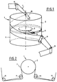
- La figure 1 est une vue schématique en perspective d'une bande enroulée selon un Ω autour d'un tambour ;
- La figure 2 est une vue de dessus de l'ensemble de la figure 1 ;
- Les figures 3 et 4 montrent schématiquement en perspective deux modes de réalisation respectifs de l'invention ;
- La figure 5 montre un schéma d'un bilame;
- La figure 6A est un schéma électrique équivalent du montage de la figure 4 ;
- La figure 6B est un schéma électrique équivalent à celui de la figure 6A, pour un signal porteur de fréquence de 250 kHz ;
- La figure 7 est un schéma synoptique d'un circuit de démodulation associé à une capacité variable ;
- La figure 8 montre en perspective le mode de réalisation de la figure 4 auquel est ajouté le circuit de correction de permitivité ;
- La figure 9 est un schéma synoptique montrant la relation des circuits de démodulation respectifs des capacités variables de mesure et de la capacité de référence ; et
- La figure 10 est un schéma montrant une boucle d'asservissement incorporant le capteur selon l'invention.
- Figure 1 is a schematic perspective view of a strip wound in an Ω around a drum;
- Figure 2 is a top view of the assembly of Figure 1;
- Figures 3 and 4 schematically show in perspective two respective embodiments of the invention;
- Figure 5 shows a diagram of a bimetallic strip;
- Figure 6A is an equivalent electrical diagram of the assembly of Figure 4;
- FIG. 6B is an electrical diagram equivalent to that of FIG. 6A, for a signal carrying a frequency of 250 kHz;
- Figure 7 is a block diagram of a demodulation circuit associated with a variable capacity;
- Figure 8 shows in perspective the embodiment of Figure 4 to which is added the permissiveness correction circuit;
- FIG. 9 is a block diagram showing the relationship of the respective demodulation circuits of the variable measurement capacities and of the reference capacity; and
- FIG. 10 is a diagram showing a control loop incorporating the sensor according to the invention.
La dispositif de la présente invention est décrit ci-après en relation avec un exemple d'application au domaine des appareils d'enregistrement/lecture à têtes magnétiques tournantes, du type connu en soi et tels que représenté schématiquement sur les figures 1 et 2.The device of the present invention is described below in relation to an example of application to the field of recording / reading apparatuses with rotating magnetic heads, of the type known per se and as shown diagrammatically in FIGS. 1 and 2.
Un tambour cylindrique 1 comprend une partie supérieure 2 et inférieure 3 séparées par une fente 4 sensiblement disposée dans un plan équatorial perpendiculaire à l'axe du tambour et à mi-hauteur de ce dernier. Dans cette fente, est prévu un élément en forme de disque 5 susceptible d'être animé d'un mouvement rotatif autour de l'axe du tambour; le disque est porteur d'une et généralement plusieurs têtes magnétiques 6 disposées régulièrement sur sa périphérie et faisant très légèrement saillie par rapport à la surface définissant la paroi du tambour. Une bande magnétique 7 est susceptible de s'enrouler hélicoïdalement autour du tambour 1, pour former, en vue de dessus comme montré sur la figure 2, un Ω. Un ensemble de galets 8 à 11 guident la bande 7 et la maintiennent selon cette configuration pendant son défilement, depuis une bobine débitrice vers une bobine réceptrice (non représentées et connues en elles-mêmes). Les informations sont enregistrées/lues sur la bande selon des segments de pistes parallèles et obliques par rapport à l'axe de la bande.A
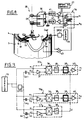
Sur les figures 3 et 4 sont représentés schématiquement deux modes de réalisation de l'invention, dans lesquels les éléments similaires portent la même référence d'une figure à l'autre. Seule la partie inférieure 3 du tambour 1 est représentée pour plus de clarté.In FIGS. 3 and 4 are diagrammatically represented two embodiments of the invention, in which similar elements bear the same reference of a figure to another. Only the
Dans la fente médiane 4 séparant les deux parties du tambour, est monté à rotation, autour de l'axe 12 du tambour, un élément en forme de disque 5 portant une pluralité de supports allongés 13, 14, 15 disposés radialement et répartis angulairement (de préférence de façon régulière). Le dispositif comporte par exemple six ou huit supports, dont seuls les supports 13, 14, et 15 sont visibles sur les figures 3 et 4. Chaque support est pourvu à son extrémité libre, c'est-à-dire l'extrémité distale par rapport à l'axe 12, d'une patte respectivement 16, 17, 18. Sur chaque patte est fixée une tête magnétique respectivement 19, 20 et 21 de façon que celles-ci fassent légèrement saillie radialement par rapport à la surface extérieure du tambour, afin de venir en contact avec la bande enroulée sur le tambour. Ainsi, il est prévu un support par tête.In the central slot 4 separating the two parts of the drum, there is mounted in rotation, around the
Les têtes magnétiques sont susceptibles d'être déplacées suivant une direction axiale, transversale à leur plan de rotation et transversalement à l'axe de la bande (c'est-à-dire parallèle à l'axe 12 du tambour) et symbolisée par la flèche f, afin de suivre les pistes parallèles inclinées portant les informations sur la bande.The magnetic heads are capable of being displaced in an axial direction, transverse to their plane of rotation and transversely to the axis of the strip (that is to say parallel to the
De manière connue, le mouvement axial de chaque tête est réalisé par le flèchissement, suivant cette même direction, du support correspondant. A cette fin, et conformément à l'exemple des figures, chaque support est constitué d'un bilame piézoélectrique. Chaque bilame (comme montré sur la figure 5) comprend trois couches conductrices parallèles 22, 23, 24 séparées deux à deux par une lamelle 25, 26 en matériau piézoélectrique; la couche centrale 23 est reliée à la masse par une impédance Z, tandis que les couches supérieure et inférieure 22, 24 sont reliées entre elles et recoivent un signal de fléchissement, de manière que les lamelles superposées subissent, sous l'effet dudit signal, respectivement un allongement et un raccourcissement, provoquant le flèchissement du bilame.In known manner, the axial movement of each head is achieved by the deflection, in this same direction, of the corresponding support. To this end, and in accordance with the example of the figures, each support consists of a piezoelectric bimetallic strip. Each bimetallic strip (as shown in FIG. 5) comprises three parallel
Chaque bilame reçoit un signal de fléchissement, engendré par des moyens de commande 27, et transmis de façon connue audit bilame par l'intermédiaire d'un ensemble de transmission 28 comportant des contacts tournants 29 (en nombre égal au nombre de bilames plus un), un circuit de connection 30, et des amplificateurs haute tension 31. A titre indicatif, les signaux de fléchissement peuvent avoir une fréquence de l'ordre de 60 à 500 Hz et une amplitude de 100 à 200 Volts.Each bimetallic strip receives a deflection signal, generated by control means 27, and transmitted in a known manner to said bimetallic strip by means of a
Il est maintenant décrit ci-après en détail, les exemples représentés aux dessins du dispositif selon l'invention, permettant de connaître à chaque instant la position axiale réelle occupée par chaque tête magnétique.The examples shown in the drawings of the device according to the invention are now described below in detail, making it possible to know at all times the real axial position occupied by each magnetic head.
Le dispositif selon l'invention comporte, pour chaque bilame, un capteur de position à capacité variable pourvu d'une armature mobile par rapport à une armature fixe, constituant une référence pour la détection de la position axiale du bilame.The device according to the invention comprises, for each bimetallic strip, a position sensor with variable capacity provided with a frame movable relative to a fixed frame, constituting a reference for the detection of the axial position of the bimetallic strip.
L'armature mobile est constituée par le bilame piézoélectrique lui-même, et plus précisément par l'une des faces métalliques externes de celui-ci, tandis que l'armature fixe 32 est constituée d'une couche conductrice plane annulaire, centrée sur l'axe 5 du tambour, et disposée sur l'une des sections droites inférieure ou supérieure du tambour faisant face à la fente 4 (cf. figures 3 et 4). Ainsi, pendant leur rotation, les bilames 13, 14 et 15 sont toujours en regard de la couche conductrice annulaire 32 constituant l'armature fixe.The movable armature is formed by the piezoelectric bimetal itself, and more precisely by one of the external metallic faces of the latter, while the fixed
On comprend que tout fléchissement axial d'un bilame, sous l'effet d'un signal de fléchissement donné, entraine son écartement ou son rapprochement de l'armature annulaire fixe 32, et modifie donc la capacité de mesure variable Cm formée par ces armatures.It is understood that any axial deflection of a bimetallic strip, under the effect of a given deflection signal, causes its separation or its approximation of the fixed
Il est à noter que l'armature fixe 32 est commune à toutes les capacités variables Cm formées par l'association bilame/armature fixe. Sur les figures 3 et 4, la couche annulaire 32 est disposée sur la section droite inférieure du tambour faisant face à la fente; elle se trouve donc en regard de la face inférieure conductrice de chaque bilame ; en variante, la couche annulaire 32 peut être fixée sur la section droite supérieure du tambour, de manière à être disposée au dessus des bilames.It should be noted that the fixed
Sont décrits ci-après les moyens de mesure associés à chaque capteur à capacité variable, autrement dit à chaque couple bilame/armature fixe, et destinés à permettre la mesure de la capacité de mesure Cm ainsi formée.Are described below the measurement means associated with each variable capacity sensor, in other words with each bimetallic strip / fixed armature, and intended to allow the measurement of the measurement capacity C m thus formed.
Le dispositif selon l'invention repose sur le principe de la mesure de l'amplitude d'un signal modulé en amplitude, soumis à une démodulation synchrone, afin de réduire l'influence de signaux parasites. On injecte à l'une des armatures un signal d'entrée alternatif, dit de détection par opposition au signal de fléchissement, et également appelé ci-après signal d'entrée porteur, et dont la fréquence "fp" joue le rôle de fréquence porteuse, soit V = Vp sin 2 π fpt. Un signal électrique alternatif d'entrée est appliqué à une armature de la capacité de mesure et l'on reçoit sur l'autre armature un signal de sortie modulé, ladite autre armature étant reliée à la masse par une impédance résistive appelée Z. Chaque capacité de mesure Cm est constituée d'un bilame et de l'armature fixe de référence 32.The device according to the invention is based on the principle of measuring the amplitude of an amplitude-modulated signal, subjected to a synchronous demodulation, in order to reduce the influence of spurious signals. An alternative input signal, called a detection signal as opposed to the deflection signal, and also called hereinafter a carrier input signal, is injected into one of the reinforcements. frequency "f p " plays the role of carrier frequency, ie V = V p sin 2 π f p t. An alternating electrical input signal is applied to an armature of the measurement capacitance and a modulated output signal is received on the other armature, said other armature being connected to ground by a resistive impedance called Z. Each capacitance Cm consists of a bimetallic strip and the fixed
Le signal de détection de sortie (ou encore signal de sortie modulé par opposition à un signal d'entrée porteur) présente un amplitude (avec 2 π fp = wp):
Cm étant fonction de "d", distance séparant les armatures de chaque capacité, Vs est de la forme
![]()
où f(d) est la fonction de "d" visée à la formule 1.The output detection signal (or alternatively modulated output signal as opposed to a carrier input signal) has an amplitude (with 2 π f p = w p ):
Cm being a function of "d", distance separating the reinforcements from each capacity, V s is of the form
![]()
where f (d) is the function of "d" referred to in
La mesure de l'amplitude du signal de sortie permet de calculer la valeur de "d" représentative de la position de la tête magnétique. En se référant aux figures 3 à 5 et 7, les moyens de mesure comprennent un générateur 33 engendrant un signal d'entrée porteur appliqué à l'une des armatures, et des moyens de démodulation 34 recevant sur une entrée le signal d'entrée porteur et dont l'autre entrée reçoit le signal de sortie modulé issu de l'autre armature. Les moyens de démodulation 34 comportent un circuit de démodulation 35₁, ..., 35N pour chaque bilame ; chaque circuit de démodulation 35i (i = 1,..,N) comprend (cf figure 7) un multiplieur 36 à deux entrées (e₁ et e₂) reliées respectivement au générateur 33i et par un amplificateur 37, à l'une des armatures du condensateur variable de mesure Cm ; la sortie du multiplieur 36 est appliquée à un filtre passe-bas 38 dont la sortie est reliée à un inverseur analogique 39, dont la fonction est de délivrer un signal de sortie inverse du signal d'entrée, lui-même suivi d'un amplificateur 40 ; la sortie si délivre un signal final représentatif de la position du bilame par rapport à l'armature fixe annulaire 32. De préférence, chaque signal final est appliqué aux moyens de commande 27 afin de réaliser une boucle de contre-réaction, comme montré sur la figure 10.Measuring the amplitude of the output signal makes it possible to calculate the value of "d" representative of the position of the magnetic head. With reference to FIGS. 3 to 5 and 7, the measurement means comprise a
Les figures 3 et 4 montrent deux formes respectives de réalisation dont les particularités propres sont ci-après décrites.Figures 3 and 4 show two respective embodiments whose specific features are described below.
Dans la première forme de réalisation, montrée sur la figure 3, le générateur 33 engendre N signaux d'entrée porteurs (N étant le nombre de bilames) de fréquences porteuses différentes qui sont appliqués à chacun des N bilames, qui reçoivent aussi le signal de fléchissement issu des moyens de commande 27, par l'intermédiaire des amplificateurs haute tension 31, des circuits de connection 30 et des contacts tournants 29. Les N signaux d'entrée porteurs sont également appliqués respectivement à une première entrée de chaque circuit de démodulation 35₁,35N, dont la seconde entrée reçoit les N signaux de sortie modulé provenant de l'armature fixe annulaire 32. A titre indicatif, les N fréquences porteuses sont de l'ordre de quelques centaines de kHz.In the first embodiment, shown in FIG. 3, the
Dans une seconde forme de réalisation, montrée sur la figure 4, le générateur 33 engendre des signaux d'entrée porteurs, de fréquence unique, appliqués à la première entrée de chaque circuit 34 et à l'armature annulaire fixe 32 par l'intermédiaire d'un déphaseur DPHI de 90°. Les signaux de sortie, issus de chaque armature mobile (chaque bilame) sont transmis à la seconde entrée 21 de chaque circuit 34i, via les contacts tournants 29 et le circuit connection 30, par l'intermédiaire de circuits de multiplexage 41 dont la fonction est décrite ci-après. Ainsi, les signaux de fléchissement issus de moyens de commande 27 sont transmis vers les bilames dans un sens, tandis que les signaux de détection, de sortie à la fréquence porteuse modulée, sont transmis depuis les bilames dans le sens inverse.In a second embodiment, shown in FIG. 4, the
Cette seconde forme de réalisation présente un compromis optimal par sa simplicité de réalisation tant sur le plan mécanique qu'électronique et évite la transmission simultanée de plusieurs signaux différents (de fléchissement d'une part et de détection d'autre part) sur la même ligne.This second embodiment presents an optimal compromise by its simplicity of realization both mechanically and electronically and avoids the simultaneous transmission of several different signals (deflection on the one hand and detection on the other hand) on the same line .
Le multiplexage en fréquence par le circuit 41 est décrit ci-après en référence aux figures 6A et 6B montrant chacune un schéma électronique correspondant au dispositif de la figure 4 et pour une capacité de mesure Cm, c'est-à-dire un bilame. Il est entendu qu'à chaque bilame correspond un montage tel que représenté à la figure 6A, à l'exception des moyens de commande 27 et du générateur 33, communs à tous les bilames.Frequency multiplexing by
En référence à la figure 6A, la capacité de mesure Cm reçoit sur une première armature, correspondant à l'armature fixe 32, par l'intermédiaire d'un déphaseur DPHI, un signal d'entrée porteur issu du générateur 33 ; la seconde armature de la capacité Cm, correspondant à l'armature mobile (le bilame 13) est reliée d'une part à un circuit de multiplexage en fréquence 41 par une ligne 42, et d'autre part à une branche reliée à la masse comprenant une capacité Cp (représentative de la capacité propre du bilame et valant environ 10 nF) et une impédance Z ; le circuit 41 est constitué d'une bobine L recevant, par l'amplificateur haute tension 31, le signal de fléchissement issu des moyens de commande 27, et reliée à un filtre R/C dont le point milieu, délivrant le signal modulé, est relié à une première entrée du circuit de démodulation 35i ; la seconde entrée de ce dernier est reliée au générateur 33. On suppose que le signal de fléchissement a une fréquence de 500 Hz et une tension d'environ 150 Volts et le signal de détection porteur une fréquence de 250 kHz. A titre indicatif, L = 10 mH , R = 10 KΩ, C = 680 pF et Z = 10KΩ.With reference to FIG. 6A, the measurement capacity C m receives on a first armature, corresponding to the fixed
La bobine L présente une impédance faible à 200 Hz et une impédance forte à 250 kHz. Le signal de fléchissement à relative haute tension ne parvient pas au circuit 35i grâce au filtre RC. A noter que l'impédance Z évite à la ligne 42 d'être reliée à la masse.The coil L has a low impedance at 200 Hz and a high impedance at 250 kHz. The deflection signal at relative high voltage does not reach
La figure 6B est un schéma équivalent de celui de la figure 7A à la fréquence du signal de détection porteur de 250 kHz. C et Cp sont considérés comme des court-circuits, car les termes correspondants 1/C w et 1/Cp w sont néglibeables devant respectivement R et Z ; la bobine L est ramenée à la masse et présente une impédance grande devant R en parallèle sur Z (R \\ Z). Soit Zeq = R \\ Z, le signal de sortie modulé "V", provenant de l'armature mobile (bilame) et délivré à sortie du circuit 41, est de la forme
où wp correspond à la fréquence du signal d'entrée porteur et Ap est l'amplitude du signal porteur ; en faisant l'hypothèse que Zeq Cm wp < < 1. (Compte tenu des valeurs respectives de ces grandeurs) on obtient un signal de sortie modulé
![]()
qui est injecté dans le circuit 35i ; son amplitude est
![]()
avec
- ε :
- permitivité de l'air
- S :
- surface des armatures en regard
- d :
- distance séparant les armatures
where w p corresponds to the frequency of the carrier input signal and A p is the amplitude of the carrier signal; by assuming that Z eq C m w p <<1. (Taking into account the respective values of these quantities) we obtain a modulated output signal
which is injected into
with
- ε:
- air permeability
- S:
- facing reinforcement area
- d:
- distance between the reinforcements
L'élément inverseur 39 de chaque circuit de démodulation 35i (cf. figure 7) inverse le signal reçu afin de délivrer un signal dont l'amplitude est de la forme
![]()
et qui est ensuite soumis à une amplification par l'amplificateur 40. Le signal final est directement exploitable, car donnant directement la valeur de "d" représentative de la position suivant l'axe vertical de la tête portée par le bilame correspondant.The inverting
![]()
and which is then subjected to amplification by the
L'élément inverseur 39 et l'amplificateur 40 sont représentés incorporés dans le circuit de démodulation 35i pour des raisons de clarté et de simplification, bien que strictement parlant, ces deux éléments ne soient pas directement liés à l'opération de démodulation.The inverting
Afin de tenir compte des variations de permitivité de l'air, (suite à un changement de température, salinité, hygrométrie), dont la valeur ε intervient dans la formule du calcul de la distance "d" séparant les armatures, le dispositif selon l'invention comprend avantageusement un circuit de correction, décrit ci-après en relation avec les figures 9 et 10. Celles-ci montrent un exemple de réalisation, pourvu du circuit de correction, et correspondant respectivement aux réalisations des figures 4 et 7.In order to take account of the variations in air permeability, (following a change in temperature, salinity, hygrometry), whose value ε intervenes in the formula for calculating the distance "d" separating the reinforcements, the device according to l The invention advantageously comprises a correction circuit, described below in relation to FIGS. 9 and 10. These show an exemplary embodiment, provided with the correction circuit, and corresponding respectively to the embodiments of FIGS. 4 and 7.
Le circuit de correction (cf figure 9) comporte une capacité de référence Cref et un circuit de démodulation 43, dont une première entrée e₁ reçoit le signal de détection porteur (depuis le générateur 33) et dont la seconde entrée e₂ est reliée à la première armature de la capacité de référence ; la seconde armature de cette dernière est reliée par le déphaseur DPHI au générateur 33.The correction circuit (cf. FIG. 9) comprises a reference capacitance C ref and a demodulation circuit 43, of which a first input e₁ receives the carrier detection signal (from the generator 33) and of which the second input e rel is connected to the first frame of the reference capacity; the second armature of the latter is connected by the phase shifter DPHI to the
Le circuit 43 comporte un multiplieur 36, un amplificateur 37 et un filtre passe-bas 38, ces trois éléments étant similaires à ceux des circuits de démodulation 35i associée à chaque capacité de mesure Cm. La sortie du circuit 43 est reliée à une entrée d'ajustement de chacun des éléments inverseurs 39 des circuits 35i respectifs.The circuit 43 comprises a
La figure 8 montre un exemple de réalisation de la capacité de référence Cref comprenant en deux armatures cylindriques concentriques et coaxiales au tambour. La première armature 44 est constituée d'une bande cylindrique de diamètre égal au diamètre intérieur de l'armature annulaire 32 des capacités de mesure Cm ; cette armature 44 est constituée par un rabat (dans un plan de section axiale) de l'armature annulaire 32. La seconde armature cylindrique 45 est placée en regard de l'armature 44, à une distance radiale donnée.FIG. 8 shows an exemplary embodiment of the reference capacity C ref comprising in two concentric cylindrical reinforcements and coaxial with the drum. The
A l'instar des N capacités de mesure Cm, le signal modulé, issu de l'armature 45 de la capacité de référence Cref, subit une démodulation synchrone en amplitude par le circuit 43 qui délivre un signal de correction appliqué à chacun des éléments inverseurs 39. Est ainsi introduit un facteur correctif dans la valeur de ε intervenant dans la formule (5), afin de tenir compte des variations de ε de l'air ambiant dans lequel baignent les capacités de mesure Cm.Like the N measurement capacities C m , the modulated signal, coming from the
Avantageusement, le signal portant l'information relative à la distance d séparant le bilame de l'armature de référence est injecté dans les moyens 27 de commande de fléchissement pour former une boucle d'asservissement, comme décrit sur la figure 10, montrant une forme de réalisation similaire à la variante de la figure 4. Les éléments similaires de chacune des figures 4 et 10 portent les mêmes références.Advantageously, the signal carrying the information relating to the distance d separating the bimetallic strip from the reference frame is injected into the deflection control means 27 to form a control loop, as described in FIG. 10, showing a shape similar in embodiment to FIG. 4. The similar elements in each of FIGS. 4 and 10 have the same references.
Le condensateur Cm représente le condensateur variable de mesure. Les sorties s₁, ..sN des moyens de démodulation sont reliées aux moyens 27 de commande de fléchissement des bilames, de manière que chaque signal de fléchissement (issus des moyens 27) soit corrigé par le signal de sortie incorporant la position effective du bilame.The capacitor Cm represents the variable measurement capacitor. The outputs s₁, ..s N of the demodulation means are connected to the bending control means 27 for bimetallic strips, so that each bending signal (coming from means 27) is corrected by the output signal incorporating the effective position of the bimetallic strip .
Claims (9)
- A device for detecting the positions of a plurality of recording/read heads (19, 20, 21) for use with a tape (7), said device being for use in rotating-head recording/read apparatus comprising:
a cylindrical drum (1) against whose surface said tape (7) is helically wound, said drum (1) having a slot (4) in an equatorial plane of said drum (1);
control means (27) for generating bending signals; and
a plurality of elongate supports (13, 14, 15) angularly distributed around the axis of the drum (1), each support (13, 14, 15):
being secured to a rotary component (5) mounted to rotate in said equatorial plane about the said axis of the drum (1); being adapted to receive a recording/read head (19, 20, 21) at its free end; and being capable of responding to a bending signal generated by said control means (7), by bending in a direction (f) transverse to the direction of relative displacement between the head and the tape, in such a manner as to displace the head (19, 20, 21) in said transverse direction (f);
said device comprising:
for each support, a variable capacitance position sensor (Cm) comprising:
both an annular fixed plate (32) secured to the drum (1), coaxial therewith, and common to all of the position sensors; and a moving plate (24) secured to the corresponding support (13, 14, 15);
and measuring means (33, 34, 35) sensitive to the response of the position sensors and adapted to provide signals representative of the position of each support, and consequently of each head. - A device according to claim 1, characterized in that the head support comprises a piezoelectric bimorph strip (13, 14, 15) having one of its faces constituting the moving plate (24) of the variable capacitance (Cm).
- A device according to claim 1 or 2, characterized in that the measurement means comprise an alternating electric signal generator (33) for generating a "carrier" input alternating electrical signal which is applied to one of the plates of the variable capacitance (Cm) by means of an amplifier (31), and demodulation means (34) having one input connected to the output from the generator and having its other input connected to the other plate of the variable capacitance.
- A device according to any preceding claim, characterized in that the fixed plate (32) is constituted by a metal layer which is disposed on one of the bottom or top faces of said slot (4), and facing the path of the rotating head support (13, 14, 15).
- A device according to claim 3 or 4, characterized in that the generator (33) generates as many signals at different frequencies as there are head supports and applies each of said signals to a respective one of the supports, and in that the demodulation means (34) comprise a demodulation circuit (35) for each frequency associated with a head support (13, 14, 15).
- A device according to claim 3 or 4, characterized in that the generator (33) generates a carrier input signal of given frequency and is connected to the fixed plate (32), the demodulation means (35) including a demodulation circuit (35i) for each head support (13, 14, 15).
- A device according to claim 6, characterized in that the measurement means include a frequency multiplexer circuit (MULTIPL) for transmitting the bending signal to the support in one direction via bending signal transmission means (28, 29) and the output signal from the moving plate (24) in the opposite direction via said bending signal transmission means, said output signal containing position information relating to the moving plate for onward transmission to the corresponding demodulation circuit (35i).
- A device according to any one of claims 5 to 7, characterized in that the measurement means (33, 34, 35) comprise a 90° phase shifter circuit (DPHI) to which the carrier input signal or the modulated output signal is applied.
- A device according to any preceding claim, characterized in that it includes a correction circuit (43) for taking account of variations in the permitivity of ambient air, said circuit comprising a reference capacitance (Cref) placed in the vicinity of the variable capacitance (Cm), said circuit being connected to said measurement means (34) in such a manner as to deliver a correction signal which is applied thereto.
Priority Applications (1)
| Application Number | Priority Date | Filing Date | Title |
|---|---|---|---|
| AT87402849T ATE74680T1 (en) | 1986-12-19 | 1987-12-15 | DEVICE FOR DETECTING THE POSITION OF A NUMBER OF MAGNETIC HEADS. |
Applications Claiming Priority (2)
| Application Number | Priority Date | Filing Date | Title |
|---|---|---|---|
| FR8617789A FR2608825B1 (en) | 1986-12-19 | 1986-12-19 | DEVICE FOR DETECTING THE POSITION OF A MAGNETIC HEAD |
| FR8617789 | 1986-12-19 |
Publications (2)
| Publication Number | Publication Date |
|---|---|
| EP0279132A1 EP0279132A1 (en) | 1988-08-24 |
| EP0279132B1 true EP0279132B1 (en) | 1992-04-08 |
Family
ID=9342073
Family Applications (1)
| Application Number | Title | Priority Date | Filing Date |
|---|---|---|---|
| EP87402849A Expired - Lifetime EP0279132B1 (en) | 1986-12-19 | 1987-12-15 | Device for detecting the position of a plurality of magnetic heads |
Country Status (8)
| Country | Link |
|---|---|
| US (1) | US4910615A (en) |
| EP (1) | EP0279132B1 (en) |
| JP (1) | JPS63253518A (en) |
| AT (1) | ATE74680T1 (en) |
| DE (1) | DE3778146D1 (en) |
| ES (1) | ES2030441T3 (en) |
| FR (1) | FR2608825B1 (en) |
| GR (1) | GR3005000T3 (en) |
Families Citing this family (5)
| Publication number | Priority date | Publication date | Assignee | Title |
|---|---|---|---|---|
| JPH03288314A (en) * | 1990-04-04 | 1991-12-18 | Sharp Corp | Head position detector for rotary head type magnetic recording and reproducing device |
| US5384676A (en) * | 1991-04-19 | 1995-01-24 | Mitsubishi Denki Kabushiki Kaisha | Magnetic head position controller in a magnetic recording and reproducing apparatus |
| US6510015B2 (en) | 1999-12-10 | 2003-01-21 | Seagate Technology Llc | Magnetic disc having physical servo patterns with a magnetic carrier, and method of making and using the same |
| US20120274315A1 (en) * | 2011-04-28 | 2012-11-01 | Rhodes Michael L | Rotation Angle Measurement Assembly |
| CN114965614B (en) * | 2022-04-28 | 2023-09-22 | 山东维璟医疗器械股份有限公司 | Vitamin detector |
Family Cites Families (14)
| Publication number | Priority date | Publication date | Assignee | Title |
|---|---|---|---|---|
| US3783196A (en) * | 1971-03-22 | 1974-01-01 | Rca Corp | High-density capacitive information records and playback apparatus therefor |
| US4165523A (en) * | 1976-03-19 | 1979-08-21 | Ampex Corporation | Automatic scan tracking using an additional sensing means on a bimorph |
| US4093885A (en) * | 1976-03-19 | 1978-06-06 | Ampex Corporation | Transducer assembly vibration sensor |
| US4183060A (en) * | 1976-03-19 | 1980-01-08 | Rca Corporation | Capacitance distance sensor apparatus for video disc player/recorder |
| JPS54307U (en) * | 1977-06-04 | 1979-01-05 | ||
| GB1580008A (en) * | 1977-06-04 | 1980-11-26 | Sony Corp | Automatic head tracking system |
| NL7805802A (en) * | 1978-05-29 | 1979-12-03 | Philips Nv | DEVICE FOR CONTROLLING A PIEEZO ELECTRICAL POSITIONING ELEMENT. |
| JPS55159681A (en) * | 1979-05-31 | 1980-12-11 | Sony Corp | Tracking unit for magnetic head |
| JPS56117326A (en) * | 1980-02-18 | 1981-09-14 | Victor Co Of Japan Ltd | Rotary head type magnetic recording and reproducing device |
| JPS56156924A (en) * | 1980-05-08 | 1981-12-03 | Sony Corp | Track following device |
| US4485414A (en) * | 1980-07-07 | 1984-11-27 | Ampex Corporation | Servo system for positioning a movable transducing head assembly |
| US4471392A (en) * | 1982-03-31 | 1984-09-11 | Rca Corporation | Automatic scan tracking with ringing control |
| JPS59104722A (en) * | 1982-12-06 | 1984-06-16 | Hitachi Ltd | Magnetic recording and reproducing device |
| JPH0695377B2 (en) * | 1985-03-12 | 1994-11-24 | ソニー株式会社 | Bimorph drive for bimorph heads |
-
1986
- 1986-12-19 FR FR8617789A patent/FR2608825B1/en not_active Expired - Fee Related
-
1987
- 1987-12-15 AT AT87402849T patent/ATE74680T1/en active
- 1987-12-15 DE DE8787402849T patent/DE3778146D1/en not_active Expired - Fee Related
- 1987-12-15 EP EP87402849A patent/EP0279132B1/en not_active Expired - Lifetime
- 1987-12-15 ES ES198787402849T patent/ES2030441T3/en not_active Expired - Lifetime
- 1987-12-18 JP JP62321184A patent/JPS63253518A/en active Pending
- 1987-12-21 US US07/136,483 patent/US4910615A/en not_active Expired - Fee Related
-
1992
- 1992-06-19 GR GR920401339T patent/GR3005000T3/el unknown
Also Published As
| Publication number | Publication date |
|---|---|
| FR2608825B1 (en) | 1994-12-30 |
| EP0279132A1 (en) | 1988-08-24 |
| US4910615A (en) | 1990-03-20 |
| ES2030441T3 (en) | 1992-11-01 |
| FR2608825A1 (en) | 1988-06-24 |
| ATE74680T1 (en) | 1992-04-15 |
| GR3005000T3 (en) | 1993-04-28 |
| DE3778146D1 (en) | 1992-05-14 |
| JPS63253518A (en) | 1988-10-20 |
Similar Documents
| Publication | Publication Date | Title |
|---|---|---|
| EP3147673B1 (en) | Optomechanical physical sensor with improved sensitivity | |
| EP0335759B1 (en) | Ultrasonic anemometer | |
| EP0960361B1 (en) | Wheel work part comprising a capacitive sensing device | |
| EP0255792A1 (en) | Identification system using a retroreflection assembly and a laser beam modulator | |
| EP0015820A1 (en) | Device for measuring linear speeds without contact and without marking | |
| BE1000782A6 (en) | Device detecting the presence of a disc and possibly some of its features. | |
| EP0279132B1 (en) | Device for detecting the position of a plurality of magnetic heads | |
| FR2529670A1 (en) | SENSITIVE ELEMENT FOR CONSTRAINTS SENSOR AND SENSOR BY APPLYING | |
| EP0077693B1 (en) | Optoelectronic device for reproducing information carried on a magnetic record carrier | |
| EP0637123B1 (en) | Surface acoustic wave motor | |
| FR2727778A1 (en) | MAGNETIC ENCODER FOR READING MARKS ON AN ASSOCIATED MAGNETIC TRACK | |
| WO2001040736A1 (en) | Analog sensor for contact-free angular offset sensing | |
| WO1999046565A1 (en) | Device for measuring angular position using a magnetic sensor | |
| EP0702420B1 (en) | Surface acoustic wave motor | |
| US7301137B2 (en) | Cantilever light detectors having a mechanical cantilever to mechanically respond to illuminated light | |
| WO1998019133A1 (en) | Dimensional inspection device without ultrasonic contact | |
| EP1674878A1 (en) | Electro-optical probe for measuring electrical or electromagnetic fields with control of the wavelength of the working point | |
| FR2485224A1 (en) | BAND POSITION SENSOR AND POSITION MEASURING DEVICE INCLUDING SENSOR | |
| FR2663735A1 (en) | DEVICE FOR REGULATING LENGTH OF COURSE FOR GYROLASERS AND THESE GYROLASERS. | |
| EP0577514A1 (en) | Apparatus for the precision measurement of internal tube diameter over a long distance | |
| EP2232273B1 (en) | Method of correcting the gain of a capacitive unit and device for implementing same | |
| EP0702418B1 (en) | Progressive mechanical wave transducer | |
| WO1997018438A1 (en) | Method and device for measuring axial deviation in a tautwire alignment system | |
| FR2645262A1 (en) | LIGHT BEAM POSITION MEASURING DEVICE FOR LASER GYROMETER | |
| CH685518A5 (en) | interferometric sensor atomic resolution, use and implementation processes. |
Legal Events
| Date | Code | Title | Description |
|---|---|---|---|
| PUAI | Public reference made under article 153(3) epc to a published international application that has entered the european phase |
Free format text: ORIGINAL CODE: 0009012 |
|
| AK | Designated contracting states |
Kind code of ref document: A1 Designated state(s): AT BE CH DE ES GB GR IT LI LU NL SE |
|
| 17P | Request for examination filed |
Effective date: 19890214 |
|
| 17Q | First examination report despatched |
Effective date: 19901112 |
|
| GRAA | (expected) grant |
Free format text: ORIGINAL CODE: 0009210 |
|
| AK | Designated contracting states |
Kind code of ref document: B1 Designated state(s): AT BE CH DE ES GB GR IT LI LU NL SE |
|
| REF | Corresponds to: |
Ref document number: 74680 Country of ref document: AT Date of ref document: 19920415 Kind code of ref document: T |
|
| REF | Corresponds to: |
Ref document number: 3778146 Country of ref document: DE Date of ref document: 19920514 |
|
| ITF | It: translation for a ep patent filed |
Owner name: BARZANO' E ZANARDO MILANO S.P.A. |
|
| GBT | Gb: translation of ep patent filed (gb section 77(6)(a)/1977) | ||
| REG | Reference to a national code |
Ref country code: ES Ref legal event code: FG2A Ref document number: 2030441 Country of ref document: ES Kind code of ref document: T3 |
|
| REG | Reference to a national code |
Ref country code: GR Ref legal event code: FG4A Free format text: 3005000 |
|
| PLBE | No opposition filed within time limit |
Free format text: ORIGINAL CODE: 0009261 |
|
| STAA | Information on the status of an ep patent application or granted ep patent |
Free format text: STATUS: NO OPPOSITION FILED WITHIN TIME LIMIT |
|
| 26N | No opposition filed | ||
| PGFP | Annual fee paid to national office [announced via postgrant information from national office to epo] |
Ref country code: SE Payment date: 19931027 Year of fee payment: 7 Ref country code: CH Payment date: 19931027 Year of fee payment: 7 |
|
| PGFP | Annual fee paid to national office [announced via postgrant information from national office to epo] |
Ref country code: GR Payment date: 19931111 Year of fee payment: 7 |
|
| PGFP | Annual fee paid to national office [announced via postgrant information from national office to epo] |
Ref country code: LU Payment date: 19931116 Year of fee payment: 7 |
|
| PGFP | Annual fee paid to national office [announced via postgrant information from national office to epo] |
Ref country code: ES Payment date: 19931207 Year of fee payment: 7 |
|
| PGFP | Annual fee paid to national office [announced via postgrant information from national office to epo] |
Ref country code: BE Payment date: 19931208 Year of fee payment: 7 |
|
| PGFP | Annual fee paid to national office [announced via postgrant information from national office to epo] |
Ref country code: DE Payment date: 19931223 Year of fee payment: 7 |
|
| EPTA | Lu: last paid annual fee | ||
| PGFP | Annual fee paid to national office [announced via postgrant information from national office to epo] |
Ref country code: AT Payment date: 19931230 Year of fee payment: 7 |
|
| PG25 | Lapsed in a contracting state [announced via postgrant information from national office to epo] |
Ref country code: LU Free format text: LAPSE BECAUSE OF NON-PAYMENT OF DUE FEES Effective date: 19941215 Ref country code: AT Effective date: 19941215 |
|
| PG25 | Lapsed in a contracting state [announced via postgrant information from national office to epo] |
Ref country code: SE Effective date: 19941216 Ref country code: ES Free format text: LAPSE BECAUSE OF EXPIRATION OF PROTECTION Effective date: 19941216 |
|
| PG25 | Lapsed in a contracting state [announced via postgrant information from national office to epo] |
Ref country code: LI Effective date: 19941231 Ref country code: CH Effective date: 19941231 Ref country code: BE Effective date: 19941231 |
|
| EAL | Se: european patent in force in sweden |
Ref document number: 87402849.1 |
|
| BERE | Be: lapsed |
Owner name: SCHLUMBERGER INDUSTRIES Effective date: 19941231 |
|
| PG25 | Lapsed in a contracting state [announced via postgrant information from national office to epo] |
Ref country code: GR Free format text: THE PATENT HAS BEEN ANNULLED BY A DECISION OF A NATIONAL AUTHORITY Effective date: 19950630 |
|
| REG | Reference to a national code |
Ref country code: CH Ref legal event code: PL Ref country code: GR Ref legal event code: MM2A Free format text: 3005000 |
|
| PG25 | Lapsed in a contracting state [announced via postgrant information from national office to epo] |
Ref country code: DE Effective date: 19950901 |
|
| EUG | Se: european patent has lapsed |
Ref document number: 87402849.1 |
|
| NLS | Nl: assignments of ep-patents |
Owner name: ENERTEC S.A. |
|
| REG | Reference to a national code |
Ref country code: GB Ref legal event code: 732E |
|
| PGFP | Annual fee paid to national office [announced via postgrant information from national office to epo] |
Ref country code: GB Payment date: 19971209 Year of fee payment: 11 |
|
| PG25 | Lapsed in a contracting state [announced via postgrant information from national office to epo] |
Ref country code: GB Free format text: LAPSE BECAUSE OF NON-PAYMENT OF DUE FEES Effective date: 19981215 |
|
| PGFP | Annual fee paid to national office [announced via postgrant information from national office to epo] |
Ref country code: NL Payment date: 19981231 Year of fee payment: 12 |
|
| GBPC | Gb: european patent ceased through non-payment of renewal fee |
Effective date: 19981215 |
|
| PG25 | Lapsed in a contracting state [announced via postgrant information from national office to epo] |
Ref country code: NL Free format text: LAPSE BECAUSE OF NON-PAYMENT OF DUE FEES Effective date: 20000701 |
|
| NLV4 | Nl: lapsed or anulled due to non-payment of the annual fee |
Effective date: 20000701 |
|
| REG | Reference to a national code |
Ref country code: ES Ref legal event code: FD2A Effective date: 20010301 |
|
| PG25 | Lapsed in a contracting state [announced via postgrant information from national office to epo] |
Ref country code: IT Free format text: LAPSE BECAUSE OF NON-PAYMENT OF DUE FEES;WARNING: LAPSES OF ITALIAN PATENTS WITH EFFECTIVE DATE BEFORE 2007 MAY HAVE OCCURRED AT ANY TIME BEFORE 2007. THE CORRECT EFFECTIVE DATE MAY BE DIFFERENT FROM THE ONE RECORDED. Effective date: 20051215 |