EP0278624A1 - Trockene Abtrennung von Feststoffen - Google Patents
Trockene Abtrennung von Feststoffen Download PDFInfo
- Publication number
- EP0278624A1 EP0278624A1 EP88300620A EP88300620A EP0278624A1 EP 0278624 A1 EP0278624 A1 EP 0278624A1 EP 88300620 A EP88300620 A EP 88300620A EP 88300620 A EP88300620 A EP 88300620A EP 0278624 A1 EP0278624 A1 EP 0278624A1
- Authority
- EP
- European Patent Office
- Prior art keywords
- solids
- path
- trough
- fluidised
- air
- Prior art date
- Legal status (The legal status is an assumption and is not a legal conclusion. Google has not performed a legal analysis and makes no representation as to the accuracy of the status listed.)
- Granted
Links
- 239000007787 solid Substances 0.000 title claims description 45
- 238000000926 separation method Methods 0.000 title claims description 9
- 238000005192 partition Methods 0.000 claims abstract description 12
- 239000000463 material Substances 0.000 claims description 28
- 238000000034 method Methods 0.000 claims description 8
- 239000011236 particulate material Substances 0.000 claims description 6
- 238000005243 fluidization Methods 0.000 claims description 3
- 230000000630 rising effect Effects 0.000 claims description 2
- 238000000638 solvent extraction Methods 0.000 claims description 2
- 238000011144 upstream manufacturing Methods 0.000 claims description 2
- 239000004576 sand Substances 0.000 abstract description 13
- 239000003923 scrap metal Substances 0.000 abstract description 2
- 239000012528 membrane Substances 0.000 description 4
- 239000002245 particle Substances 0.000 description 4
- 230000033001 locomotion Effects 0.000 description 3
- 229910052751 metal Inorganic materials 0.000 description 3
- 239000002184 metal Substances 0.000 description 3
- 238000005188 flotation Methods 0.000 description 2
- 150000002739 metals Chemical class 0.000 description 2
- 229910001369 Brass Inorganic materials 0.000 description 1
- -1 Ferrous metals Chemical class 0.000 description 1
- FYYHWMGAXLPEAU-UHFFFAOYSA-N Magnesium Chemical compound [Mg] FYYHWMGAXLPEAU-UHFFFAOYSA-N 0.000 description 1
- HCHKCACWOHOZIP-UHFFFAOYSA-N Zinc Chemical compound [Zn] HCHKCACWOHOZIP-UHFFFAOYSA-N 0.000 description 1
- 239000004411 aluminium Substances 0.000 description 1
- 229910052782 aluminium Inorganic materials 0.000 description 1
- XAGFODPZIPBFFR-UHFFFAOYSA-N aluminium Chemical compound [Al] XAGFODPZIPBFFR-UHFFFAOYSA-N 0.000 description 1
- 239000010951 brass Substances 0.000 description 1
- 238000007599 discharging Methods 0.000 description 1
- 239000000428 dust Substances 0.000 description 1
- 239000011521 glass Substances 0.000 description 1
- 229910052500 inorganic mineral Inorganic materials 0.000 description 1
- 229910052749 magnesium Inorganic materials 0.000 description 1
- 239000011777 magnesium Substances 0.000 description 1
- 239000011707 mineral Substances 0.000 description 1
- 239000000203 mixture Substances 0.000 description 1
- 239000004033 plastic Substances 0.000 description 1
- 239000005060 rubber Substances 0.000 description 1
- 230000007704 transition Effects 0.000 description 1
- 239000002699 waste material Substances 0.000 description 1
- 239000011701 zinc Substances 0.000 description 1
- 229910052725 zinc Inorganic materials 0.000 description 1
Images
Classifications
-
- B—PERFORMING OPERATIONS; TRANSPORTING
- B03—SEPARATION OF SOLID MATERIALS USING LIQUIDS OR USING PNEUMATIC TABLES OR JIGS; MAGNETIC OR ELECTROSTATIC SEPARATION OF SOLID MATERIALS FROM SOLID MATERIALS OR FLUIDS; SEPARATION BY HIGH-VOLTAGE ELECTRIC FIELDS
- B03B—SEPARATING SOLID MATERIALS USING LIQUIDS OR USING PNEUMATIC TABLES OR JIGS
- B03B5/00—Washing granular, powdered or lumpy materials; Wet separating
- B03B5/28—Washing granular, powdered or lumpy materials; Wet separating by sink-float separation
- B03B5/46—Washing granular, powdered or lumpy materials; Wet separating by sink-float separation using dry heavy media; Devices therefor
Definitions
- the present invention relates to a method and apparatus for dry separation of solids such as mineral ores, waste material or scrap metal.
- a method of dry separation of solids comprising: vibration-driving a particulate material, finer than the solids, to flow round a defined endless generally horizontal path; fluidising the material for a length of the path; adding the solids to the top of the flowing material; and depthwise partitioning the flowing material downstream of the solids-addition point and within the fluidised length, whereby to separate the solids which have not settled beyond the depth of the partition from those which settled faster.
- the invention also provides a solid separator, comprising a trough defining an endless generally horizontal path, the trough having an air-permeable base over a length of the path; a distributor for solids onto the trough; and a depthwise partition in said trough at a point on said length.
- a solid separator comprising a trough defining an endless generally horizontal path, the trough having an air-permeable base over a length of the path; a distributor for solids onto the trough; and a depthwise partition in said trough at a point on said length.
- Preferably means are provided to vibrate the separator with simultaneous horizontal and vertical components.
- the separator in use contains a particulate material as an entraining medium, and preferably the partition is perforated (to retain partitioned solids but to pass any entraining medium).
- An air supply upwardly through said base is in use present, to fluidise the medium.
- the solids-addition point (the distributor) is upstream of the fluidised length, which preferably starts with an onset zone over which fluidisation progressively increases.
- the defined path is rotary.
- the rotary path is circular and the material and medium are constrained to move in the defined circular path by upstanding wall members.
- the medium is fluidised over only a length of the rotary path.
- the slower-settling material is preferably extracted by means of the partition, which is in the form of a first ramp positioned along the rotary path at a position downstream from the commencement of the fluidised portion of the rotary path, and the faster-settling material is preferably extracted by means of a second ramp starting lower than the partition and preferably positioned along the rotary path at a position downstream from the first ramp.
- the second ramp is positioned after the end of the fluidised length.
- Each ramp is preferably perforated such as to retain partitioned solids but to pass the particulate material, which can thereby continue flowing along said defined path.
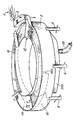
- the apparatus which as will be seen can be considered as a flowing media jigging separator, has a horizontal annular circular trough 2 which is vibrated through spring-supported mounts 4 with a motion which is clockwise-and-up/anticlockwise-and-down.
- the diameter is 2m.
- the motion derives from eccentric cams or, preferably, two exciter units attached to diagrammatically opposite mounts 4 vibrating with opposed horizontal (i.e. net rotational) and in-phase vertical components, giving a reciprocating screw-twist rising and falling at for example a resultant 45° to the horizontal.
- the frequency and amplitude of vibration of the exciter units are selected according to the size and intended throughput of the separator apparatus but again merely as a guide could be of the order of 50 Hz and 3mm.
- the apparatus is fed by a chute 6 leading to a perforated track 8 adjoining part of the trough 2 at a higher level.
- the track 8 feeds a distributor 12 for discharging feed at a single angular location into the trough 2.
- the distributor 12 Underneath the distributor 12 is an adjustable horizontal radial straight-edge (not shown) for levelling the contents of the trough 2.
- a helical upwards perforated ramp 14 occupies the trough, starting with a strictly radial and horizontal splitter edge 14a.
- the edge is about half-way down the depth of the trough; its exact height and distance from the distributor are determined by trial and error.
- a second perforated and upward helical ramp 16 occupies the trough, starting at its base, at a (non-critical) later clockwise position. Both ramps 14 and 16 rise to the top of the trough and discharge their respective streams of material over the side to different collectors.
- the base of the trough from a point somewhat clockwise of the distributor 12 to a point somewhat clockwise of the splitter edge 14a, is an air-permeable membrane, the rest of the base being solid.
- the membrane passes air upwardly from a manifold 20a fed by a compressed air line 20.
- a transition zone At the anticlockwise end of the membrane is a transition zone whereby the onset of fluidisation (to be described) is graduated over an area.
- the trough is filled to a level well above the splitter edge 14a but below the brim with a dry particulate medium which is fine in comparison with the solids to be separated and which, unlike the solids, can pass through the perforated ramps 14 and 16.
- Sand is suitable, the particle size and type being selected by trial and error to suit the specific separation.
- the operational sequence of the separation apparatus is as follows.
- Typical solids to be separated comprise pieces of various materials obtained, for example, by crushing and fragmentising scrap cars, machines, 'white goods' and television sets.
- Ferrous metals are removed magnetically, leaving dust or dirt particles; rubber, plastic and glass; and pieces of light metals (magnesium, aluminium) and denser metals (zinc, brass).
- the solids are screened to exclude oversize chunks and then fed by the chute 6 to the track 8.
- the exciter units are activated and their vibratory action causes the material to move in a clockwise direction along the perforated track 8, where undersize solids are lost, shaken through the perforations.
- the perforations may lose solids of volumes up to 100 times the volume of a grain of sand.
- the remaining solids drop off the lid of the distributor 12 into the trough 2.
- the sand here has been levelled by the straight-edge and is not fluidised.
- Air through the line 20 fluidises the sand in the arc above the membrane, to a modest bed expansion (a few tens of percent) starting gradually over an area at the anticlockwise end.
- the vibratory action simultaneously causes all the sand in the trough 2 to advance slowly clockwise.
- the solids are entrained in this advance, and the very lightest solids "float" on the surface of the fluidised and advancing sand, while the remaining solids sink at varying rates, according to a phenomenon known as hindered settling induced by the combination of vertical (fluidised and vibrated) and horizontal (vibrated) motions.
- the rest therefore moves up the ramp 14 (which is also being vibrated) and is discharged over the side, for example into an annular picking tray (not shown) round which those solids move, allowing unwanted material to be hand picked therefrom.
- the ramp 14 being perforated, the sand falls through back into the trough 2 and thereby continues on round the trough to be used again in the separation process.
- the faster-settling solids are conveyed under the splitter edge 14a and along or near the base of the trough 2 until they meet the second ramp 16 the end of which is at or close to the bottom of the trough.
- These solids move up the ramp 16 which is perforated to allow the sand to be shaken through, leaving these solids to proceed up the ramp to an outlet chute (not shown).
- That chute may lead to a picking tray (e.g. a further section of the said annular picking tray, for hand picking), and thence to a collecting hopper.
- the bottom of this ramp 16 is in the non-fluidised section of the trough.
- the sand flows on round the trough 2 as shown by the hollow arrows to receive a fresh load of solids from 12 in its turn.
- two apparati can operate in series, the second receiving as feed one of the exiting solids streams of the first, and the two apparati operating with appropriately differing parameters such as splitter edge depth or grade of sand.
Landscapes
- Combined Means For Separation Of Solids (AREA)
- Separation Of Solids By Using Liquids Or Pneumatic Power (AREA)
Applications Claiming Priority (4)
| Application Number | Priority Date | Filing Date | Title |
|---|---|---|---|
| GB8702166 | 1987-01-30 | ||
| GB878702166A GB8702166D0 (en) | 1987-01-30 | 1987-01-30 | Dry media separator |
| GB878709501A GB8709501D0 (en) | 1987-04-22 | 1987-04-22 | Dry separation of solids |
| GB8709501 | 1987-04-22 |
Publications (2)
| Publication Number | Publication Date |
|---|---|
| EP0278624A1 true EP0278624A1 (de) | 1988-08-17 |
| EP0278624B1 EP0278624B1 (de) | 1991-02-27 |
Family
ID=26291854
Family Applications (1)
| Application Number | Title | Priority Date | Filing Date |
|---|---|---|---|
| EP88300620A Expired EP0278624B1 (de) | 1987-01-30 | 1988-01-26 | Trockene Abtrennung von Feststoffen |
Country Status (7)
| Country | Link |
|---|---|
| US (1) | US4857177A (de) |
| EP (1) | EP0278624B1 (de) |
| JP (1) | JPH0624644B2 (de) |
| AU (2) | AU605542B2 (de) |
| CA (1) | CA1326648C (de) |
| DE (1) | DE3861799D1 (de) |
| GB (1) | GB2200859B (de) |
Families Citing this family (5)
| Publication number | Priority date | Publication date | Assignee | Title |
|---|---|---|---|---|
| US5048693A (en) * | 1989-06-28 | 1991-09-17 | World Agrosearch, Ltd. | Method and apparatus for sorting articles with small density differences utilizing a flotation stream |
| GB2256819B (en) * | 1991-06-21 | 1996-01-03 | Multiserv Int Ltd | Separation |
| US5975442A (en) * | 1998-09-02 | 1999-11-02 | Purser; Brian | Cable granulator |
| JP5868184B2 (ja) * | 2012-01-05 | 2016-02-24 | 永田エンジニアリング株式会社 | 乾式分離方法、及び乾式分離装置 |
| CN114939475A (zh) * | 2022-05-19 | 2022-08-26 | 华侨大学 | 一种基于颗粒介质的报废汽车高效干式分选智能设备 |
Citations (4)
| Publication number | Priority date | Publication date | Assignee | Title |
|---|---|---|---|---|
| GB1085810A (en) * | 1964-05-06 | 1967-10-04 | Nat Res Dev | Gravity separation of particulate material |
| US3444996A (en) * | 1966-03-14 | 1969-05-20 | Nat Res Dev | Dry separation of mixtures of solid materials |
| US4035288A (en) * | 1973-08-06 | 1977-07-12 | Francois Gibert | Fluidized bed seed separator |
| DE2848474A1 (de) * | 1977-11-08 | 1979-05-10 | Cable Communication Access | Verfahren und vorrichtung zum trennen von partikelfoermigen materialien |
Family Cites Families (12)
| Publication number | Priority date | Publication date | Assignee | Title |
|---|---|---|---|---|
| FR528091A (fr) * | 1920-06-03 | 1921-11-05 | Henri Chabal | Procédé pour le lavage et le classement de matériaux par grosseur et par densité |
| US1801195A (en) * | 1927-10-31 | 1931-04-14 | Hydrotator Company | Process of and apparatus for separating mixed materials |
| US2007190A (en) * | 1931-12-21 | 1935-07-09 | Fraser Thomas | Process of and apparatus for separating mixed materials |
| FR898197A (fr) * | 1939-08-05 | 1945-04-12 | Krupp Fried Grusonwerk Ag | Procédé et appareil pour communiquer à des agents de classement en grains fins la propriété d'un liquide |
| US2303367A (en) * | 1939-10-23 | 1942-12-01 | Adamson Stephens Mfg Co | Coal cleaner |
| US2910179A (en) * | 1955-06-03 | 1959-10-27 | Svensson Karl Jonas Valter | Procedure and means for the separation of solid materials of different specific gravities according to the sink-and-float method |
| GB946480A (en) * | 1961-07-11 | 1964-01-15 | James Blackwood Greenshields | Solid-solid separating apparatus |
| AU3780572A (en) * | 1972-01-11 | 1973-07-12 | Wilhelm Henrik Ducker Bennet Carl | A method anda device for separating solid materials |
| JPS507156A (de) * | 1973-05-24 | 1975-01-24 | ||
| JPS5752103A (en) * | 1980-09-16 | 1982-03-27 | Hitachi Ltd | Voltage nonlinear resistor |
| JPS59189948A (ja) * | 1983-04-08 | 1984-10-27 | Masayoshi Nakamura | 固体粒を媒介とした比重分類法 |
| DE3520570C2 (de) * | 1985-06-07 | 1987-03-19 | Schönert, Klaus, Prof. Dr.-Ing., 3392 Clausthal-Zellerfeld | Setzverfahren und -Vorrichtung zur Dichtesortierung im Fein- und Feinstkornbereich |
-
1988
- 1988-01-26 GB GB8801705A patent/GB2200859B/en not_active Expired - Lifetime
- 1988-01-26 DE DE8888300620T patent/DE3861799D1/de not_active Expired - Lifetime
- 1988-01-26 EP EP88300620A patent/EP0278624B1/de not_active Expired
- 1988-01-28 US US07/149,591 patent/US4857177A/en not_active Expired - Lifetime
- 1988-01-28 AU AU10923/88A patent/AU605542B2/en not_active Ceased
- 1988-01-28 JP JP63018474A patent/JPH0624644B2/ja not_active Expired - Lifetime
- 1988-01-29 CA CA000557646A patent/CA1326648C/en not_active Expired - Fee Related
-
1989
- 1989-04-12 AU AU32697/89A patent/AU615533B2/en not_active Ceased
Patent Citations (4)
| Publication number | Priority date | Publication date | Assignee | Title |
|---|---|---|---|---|
| GB1085810A (en) * | 1964-05-06 | 1967-10-04 | Nat Res Dev | Gravity separation of particulate material |
| US3444996A (en) * | 1966-03-14 | 1969-05-20 | Nat Res Dev | Dry separation of mixtures of solid materials |
| US4035288A (en) * | 1973-08-06 | 1977-07-12 | Francois Gibert | Fluidized bed seed separator |
| DE2848474A1 (de) * | 1977-11-08 | 1979-05-10 | Cable Communication Access | Verfahren und vorrichtung zum trennen von partikelfoermigen materialien |
Also Published As
| Publication number | Publication date |
|---|---|
| AU605542B2 (en) | 1991-01-17 |
| JPH0624644B2 (ja) | 1994-04-06 |
| EP0278624B1 (de) | 1991-02-27 |
| GB2200859B (en) | 1990-11-14 |
| AU1092388A (en) | 1988-08-04 |
| US4857177A (en) | 1989-08-15 |
| GB8801705D0 (en) | 1988-02-24 |
| AU615533B2 (en) | 1991-10-03 |
| CA1326648C (en) | 1994-02-01 |
| AU3269789A (en) | 1989-08-10 |
| GB2200859A (en) | 1988-08-17 |
| JPS63194752A (ja) | 1988-08-11 |
| DE3861799D1 (de) | 1991-04-04 |
Similar Documents
| Publication | Publication Date | Title |
|---|---|---|
| JP7812237B2 (ja) | 乾式分離方法、及び乾式分離装置 | |
| US2310894A (en) | Dry flotation, and media and apparatus therefor | |
| US4128474A (en) | Process for cleaning and dewatering fine coal | |
| US2356648A (en) | Classifying process and apparatus | |
| US2209618A (en) | Preparing bulk material and apparatus therefor | |
| Mijał et al. | Development of dry coal gravity separation techniques | |
| US3945915A (en) | Method of and apparatus for assorting particles according to the physical characteristics thereof | |
| AU2017306575B2 (en) | An apparatus and method for the dry separation of particles | |
| US3367501A (en) | Dry-cleaning of large or small coal or other particulate materials containing components of different specific gravities | |
| US3674144A (en) | Gravity separation of granular materials | |
| US4857177A (en) | Dry separation of solids | |
| US4319995A (en) | Process and apparatus for separating particles by relative density | |
| JP7265747B2 (ja) | 乾式分離方法、及び乾式分離装置 | |
| US3904517A (en) | Method of and apparatus for assorting particles according to the physical characteristics thereof | |
| US3467594A (en) | Separating method and apparatus | |
| US5586660A (en) | Process and apparatus for screening a stream of bulk material | |
| US3599791A (en) | Hydraulic sorting apparatus | |
| US4584094A (en) | Method and apparatus for reclaiming coal | |
| US2279590A (en) | Apparatus for separating particulate materials | |
| US1315880A (en) | Process of and apparatus for sizing and separating comminuted material | |
| Chelgani et al. | Gravity separation | |
| US2999596A (en) | Method and apparatus for the segregation of particulate material | |
| RU2842380C1 (ru) | Классификатор и способ классификации | |
| US12240016B2 (en) | Classifier and method of classifying | |
| Dodbiba et al. | Air tabling—a dry gravity solid–solid separation technique |
Legal Events
| Date | Code | Title | Description |
|---|---|---|---|
| PUAI | Public reference made under article 153(3) epc to a published international application that has entered the european phase |
Free format text: ORIGINAL CODE: 0009012 |
|
| AK | Designated contracting states |
Kind code of ref document: A1 Designated state(s): BE DE FR IT NL |
|
| 17P | Request for examination filed |
Effective date: 19881107 |
|
| 17Q | First examination report despatched |
Effective date: 19900221 |
|
| GRAA | (expected) grant |
Free format text: ORIGINAL CODE: 0009210 |
|
| AK | Designated contracting states |
Kind code of ref document: B1 Designated state(s): BE DE FR IT NL |
|
| ITF | It: translation for a ep patent filed | ||
| ET | Fr: translation filed | ||
| REF | Corresponds to: |
Ref document number: 3861799 Country of ref document: DE Date of ref document: 19910404 |
|
| PLBE | No opposition filed within time limit |
Free format text: ORIGINAL CODE: 0009261 |
|
| STAA | Information on the status of an ep patent application or granted ep patent |
Free format text: STATUS: NO OPPOSITION FILED WITHIN TIME LIMIT |
|
| 26N | No opposition filed | ||
| ITPR | It: changes in ownership of a european patent |
Owner name: CESSIONE;BRITISH TECHNOLOGY GROUP LIMITED |
|
| REG | Reference to a national code |
Ref country code: FR Ref legal event code: TP |
|
| NLS | Nl: assignments of ep-patents |
Owner name: BRITISH TECHNOLOGY GROUP LTD TE LONDEN, GROOT-BRIT |
|
| PGFP | Annual fee paid to national office [announced via postgrant information from national office to epo] |
Ref country code: NL Payment date: 20011206 Year of fee payment: 15 |
|
| PGFP | Annual fee paid to national office [announced via postgrant information from national office to epo] |
Ref country code: FR Payment date: 20011210 Year of fee payment: 15 |
|
| PGFP | Annual fee paid to national office [announced via postgrant information from national office to epo] |
Ref country code: BE Payment date: 20020226 Year of fee payment: 15 |
|
| PG25 | Lapsed in a contracting state [announced via postgrant information from national office to epo] |
Ref country code: BE Free format text: LAPSE BECAUSE OF NON-PAYMENT OF DUE FEES Effective date: 20030131 |
|
| PG25 | Lapsed in a contracting state [announced via postgrant information from national office to epo] |
Ref country code: NL Free format text: LAPSE BECAUSE OF NON-PAYMENT OF DUE FEES Effective date: 20030801 |
|
| PG25 | Lapsed in a contracting state [announced via postgrant information from national office to epo] |
Ref country code: FR Free format text: LAPSE BECAUSE OF NON-PAYMENT OF DUE FEES Effective date: 20030930 |
|
| NLV4 | Nl: lapsed or anulled due to non-payment of the annual fee |
Effective date: 20030801 |
|
| REG | Reference to a national code |
Ref country code: FR Ref legal event code: ST |
|
| PG25 | Lapsed in a contracting state [announced via postgrant information from national office to epo] |
Ref country code: IT Free format text: LAPSE BECAUSE OF NON-PAYMENT OF DUE FEES;WARNING: LAPSES OF ITALIAN PATENTS WITH EFFECTIVE DATE BEFORE 2007 MAY HAVE OCCURRED AT ANY TIME BEFORE 2007. THE CORRECT EFFECTIVE DATE MAY BE DIFFERENT FROM THE ONE RECORDED. Effective date: 20050126 |
|
| PGFP | Annual fee paid to national office [announced via postgrant information from national office to epo] |
Ref country code: DE Payment date: 20060119 Year of fee payment: 19 |
|
| PG25 | Lapsed in a contracting state [announced via postgrant information from national office to epo] |
Ref country code: DE Free format text: LAPSE BECAUSE OF NON-PAYMENT OF DUE FEES Effective date: 20070801 |