EP0278564B1 - Dispositif pour fours à micro-ondes - Google Patents
Dispositif pour fours à micro-ondes Download PDFInfo
- Publication number
- EP0278564B1 EP0278564B1 EP88200181A EP88200181A EP0278564B1 EP 0278564 B1 EP0278564 B1 EP 0278564B1 EP 88200181 A EP88200181 A EP 88200181A EP 88200181 A EP88200181 A EP 88200181A EP 0278564 B1 EP0278564 B1 EP 0278564B1
- Authority
- EP
- European Patent Office
- Prior art keywords
- oven
- cavity
- arrangement
- microwave
- reflecting element
- Prior art date
- Legal status (The legal status is an assumption and is not a legal conclusion. Google has not performed a legal analysis and makes no representation as to the accuracy of the status listed.)
- Expired
Links
- 239000003989 dielectric material Substances 0.000 claims description 5
- 239000004020 conductor Substances 0.000 claims description 4
- 230000005855 radiation Effects 0.000 claims description 3
- 238000004519 manufacturing process Methods 0.000 description 3
- 238000005452 bending Methods 0.000 description 2
- 238000009826 distribution Methods 0.000 description 2
- 238000010438 heat treatment Methods 0.000 description 2
- 239000004743 Polypropylene Substances 0.000 description 1
- 239000000470 constituent Substances 0.000 description 1
- 239000000463 material Substances 0.000 description 1
- 239000002184 metal Substances 0.000 description 1
- 238000000034 method Methods 0.000 description 1
- -1 polypropylene Polymers 0.000 description 1
- 229920001155 polypropylene Polymers 0.000 description 1
- 238000003466 welding Methods 0.000 description 1
Images
Classifications
-
- H—ELECTRICITY
- H05—ELECTRIC TECHNIQUES NOT OTHERWISE PROVIDED FOR
- H05B—ELECTRIC HEATING; ELECTRIC LIGHT SOURCES NOT OTHERWISE PROVIDED FOR; CIRCUIT ARRANGEMENTS FOR ELECTRIC LIGHT SOURCES, IN GENERAL
- H05B6/00—Heating by electric, magnetic or electromagnetic fields
- H05B6/64—Heating using microwaves
- H05B6/6426—Aspects relating to the exterior of the microwave heating apparatus, e.g. metal casing, power cord
-
- H—ELECTRICITY
- H05—ELECTRIC TECHNIQUES NOT OTHERWISE PROVIDED FOR
- H05B—ELECTRIC HEATING; ELECTRIC LIGHT SOURCES NOT OTHERWISE PROVIDED FOR; CIRCUIT ARRANGEMENTS FOR ELECTRIC LIGHT SOURCES, IN GENERAL
- H05B6/00—Heating by electric, magnetic or electromagnetic fields
- H05B6/64—Heating using microwaves
- H05B6/76—Prevention of microwave leakage, e.g. door sealings
Definitions
- the invention relates to an arrangement in a microwave oven that comprises an oven cavity bounded by a plurality of conductive walls, a reclosable oven door giving access to the oven cavity and a microwave source mounted external of the oven cavity for feeding microwave energy into the interior of the oven cavity.
- the oven cavity is a rectangular parallelepiped that has a highly symmetrical shape.
- the shape of the oven cavity must have a certain degree of unsymmetry for reasons of manufacturing. This applies for instance to ovens of the "single-wall" type, in which at least one cavity wall also forms a part of the outer envelope wall of the oven. At the front of such an oven the wall common to cavity and outer envelope must be bent for producing an access section cooperating with the oven door to provide a microwave seal, and also for producing a front having a sufficient mechanical stability.
- an elongated groove-shaped wall recess will be formed that has an open side facing the oven cavity and that leads to an unsymmetry of the microwave field in the oven cavity, which unsymmetry is attributable to the fact that such a recess will involve a discontinuity of the microwave field boundary constituted by the oven cavity wall.
- Such groove-shaped recesses will aggravate the object of achieving a good microwave field distribution and thereby a uniform heating of the load in the oven cavity, in particular because the geometry and the size of the load will vary.
- the invention relates to a microwave oven having an oven cavity, at the manufacturing of which such groove-shaped recesses leading to unsymmetries of the microwave field have been formed in at least one of the cavity walls, and it is an object of the invention to substantially eliminate the influence of these recesses on the microwave field in a simple manner so that the oven cavity, as regards its microwave aspects, operates as a space having a highly symmetrical shape.
- this object is achieved in that reflecting elements of conductive material are provided at the open side of the recesses facing the oven cavity, the reflecting elements covering a part of the open recess side and being dimensioned and disposed so as to substantially reflect all incident radiation at the operational frequency of the microwave oven.
- the influence of the recesses on the microwave field will be substantially eliminated in a very simple manner without using a complete metallic covering of the recesses by means of conductive material, such a covering requiring an effective galvanic contact, made by seam-welding or the like, between the covering material and the cavity wall parts surrounding the recesses in order to avoid sparking.
- the reflecting element has the shape of a substantially plane conductive strip having an essentially rectangular form.
- the width and the length of this strip as well as its position in the recess will be decisive for its functioning in reflecting incident microwave energy, that is to say in adapting the actual shape of the oven cavity to the shape of a space producing the best possible microwave field distribution and heating, which space has a highly symmetrical shape.
- the reflecting element is completely or partly covered by dielectric material, for example polypropylene.
- the dielectric material can be shaped as a plate covering the entrance opening of the recess and simultaneously supporting the reflecting element at its rear side.
- the dimensioning of the reflecting element in the shape of a conductive strip for achieving the desired function will then be influenced by the dielectric properties of the plate and also by the presence of an air gap, if any, between the plate and the element.
- Such a dielectric plate will also serve as protection against dirt which could penetrate into the recess.
- this strip has bent longer side portions so that the element will have a substantially U-shaped cross section.
- the reflecting element has no galvanic contact with the oven cavity walls.
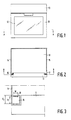
- reference numeral 10 designates a microwave oven cavity
- reference numeral 11 designates a door for closing an opening giving acess to the cavity
- reference numeral 12 designates a window in the door 11
- reference numeral 13 designates an operation and control unit comprising all electrical components that are necessary for the operation of the oven.
- the microwave oven is of the "single-wall" type and in particular the side walls 14, 15 of the oven cavity 10 also forms a part of the outer envelope of the oven.
- the oven cavity 10 is manufactured by bending a metallic sheet.
- the oven front which is adapted to cooperate with the door 11, is made as an integral constituent part of the cavity walls 14, 15 and is formed by bent portions of these walls.
- Elongated recesses or grooves 16 and 17, which are open towards the interior of the oven cavity, will then be formed at the oven front on each side of the access opening. These recesses involve an unsymmetry in the shape of the oven cavity and will disturb the microwave field pattern in this oven cavity.
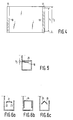
- elongated matching or reflecting elements 18, 19 of metallic conductive material are arranged in accordance with the invention in a position that substantially coincides with the entrance opening of the recesses.
- the reflecting elements are in the shape of rectanfular strips that have a given length l1 related to the length l2 of the recess and a given width w, and that are disposed at a given distance d1 from the bottom of the recess related to the overall depth d2 of the recess.
- the entrance of the recess is covered by a dielectric plate 20 that at the same time serves as support for the reflecting element 18. If desired, there can be a small distance d3 between the plate 20 and the element 18. This air gap d3 has also an influence on the optimal dimensioning of the reflecting element 18.
- the reflecting element consists of a plane part 21 and two bent side portions 22, 23. These portions can, for example, have a height of 2mm.
- a variant of this embodiment in which the reflecting element 24 almost fills the whole recess, is shown in Fig. 6b.
- a further embodiment of the reflecting element is shown in Fig. 6a, where the element consists of two oblique conductive strips 25, 26 so that it will have a V-shaped cross section.
- the ends of the reflective element may be shaped in various ways, e.g. these ends may be rounded in order to minimize the risk of sparking.
- the dielectric properties of this plate can be selected in such a manner that the element, at an optimal dimensioning, will have a length and width that minimize the risk of sparking between the element and adjacent metal wall surfaces.
- Such a dimensioning of the reflecting element, providing a sufficiently wide gap between the element and adjacent cavity walls, is also important from the viewpoint of avoiding tolerance problems at the manufacturing and assembling.
- the reflecting element does not need to be vertical but can make a certain slight angle with the vertical, e.g. in order to achieve adaption to the load that is always placed near the bottom of the oven cavity.
Landscapes
- Physics & Mathematics (AREA)
- Electromagnetism (AREA)
- Electric Ovens (AREA)
- Constitution Of High-Frequency Heating (AREA)
Claims (7)
- Dispositif pour four à micro-ondes qui comprend une cavité de four (10) délimitée par plusieurs parois conductrices (14, 15) et une source de micro-ondes montée à l'extérieur de la cavité de four pour introduire de l'énergie de micro-ondes à l'intérieur de la cavité de four (10), au moins une des parois conductrices de la cavité comportant un ou plusieurs évidements en forme de rainure (16, 17) qui comportent un côté ouvert tourné vers la cavité de four et qui perturbent la configuration du champ de micro-ondes à l'intérieur de la cavité de four, caractérisé en ce que des éléments réfléchissants (18) en matière conductrice sont prévus aux côtés ouverts des évidements tournés vers la cavité de four, ces éléments réfléchissants couvrant une partie du côté ouvert de l'évidement et étant dimensionnés et positionnés de manière à réfléchir en substance tout le rayonnement incident à la fréquence de fonctionnement du four à micro-ondes.
- Dispositif suivant la revendication 1, caractérisé en ce que l'élément réfléchissant (18) est au moins partiellement couvert par de la matière diélectrique (20).
- Dispositif suivant la revendication 2, caractérisé en ce qu'une plaque de matière diélectrique couvre complètement l'orifice d'entrée de l'évidement, vu à partir de la cavité de four, et supporte simultanément l'élément réfléchissant.
- Dispositif suivant l'une quelconque des revendications 1 à 3, caractérisé en ce que l'élément réfléchissant a la forme d'une bande conductrice en substance plane (18) présentant une forme essentiellement rectangulaire.
- Dispositif suivant la revendication 4, caractérisé en ce que la bande conductrice comporte des parties latérales allongées coudées, de sorte que la bande (21, 24) présente une section transversale en substance en forme de U.
- Dispositif suivant l'une quelconque des revendications 1 à 5, caractérisé en ce que l'élément réfléchissant (18) ne présente aucun contact galvanique avec les parois (14, 15) de la cavité.
- Application d'un dispositif suivant l'une quelconque des revendications 1 à 6 dans un four à micro-ondes du type à paroi simple comportant au moins une paroi (14, 15) de la cavité qui fait également partie de l'enveloppe extérieure du four, les évidements en forme de rainure (16,17) étant formés par des parties coudées en U des parois latérales de la cavité à l'avant du four.
Applications Claiming Priority (2)
| Application Number | Priority Date | Filing Date | Title |
|---|---|---|---|
| SE8700453A SE458815B (sv) | 1987-02-06 | 1987-02-06 | Anordning vid en mikrovaagsugn samt anvaendning av anordningen |
| SE8700453 | 1987-02-06 |
Publications (2)
| Publication Number | Publication Date |
|---|---|
| EP0278564A1 EP0278564A1 (fr) | 1988-08-17 |
| EP0278564B1 true EP0278564B1 (fr) | 1991-12-18 |
Family
ID=20367415
Family Applications (1)
| Application Number | Title | Priority Date | Filing Date |
|---|---|---|---|
| EP88200181A Expired EP0278564B1 (fr) | 1987-02-06 | 1988-02-03 | Dispositif pour fours à micro-ondes |
Country Status (5)
| Country | Link |
|---|---|
| US (1) | US4855554A (fr) |
| EP (1) | EP0278564B1 (fr) |
| JP (1) | JPS63252383A (fr) |
| DE (1) | DE3866889D1 (fr) |
| SE (1) | SE458815B (fr) |
Family Cites Families (7)
| Publication number | Priority date | Publication date | Assignee | Title |
|---|---|---|---|---|
| BE757877A (fr) * | 1969-10-24 | 1971-04-01 | Amana Refrigeration Inc | Four a hyperfrequence |
| US3789178A (en) * | 1972-10-18 | 1974-01-29 | Sage Laboratories | Microwave heating apparatus |
| US4144437A (en) * | 1977-07-29 | 1979-03-13 | Litton Systems, Inc. | Microwave oven energy stirrer |
| JPS6035992Y2 (ja) * | 1980-11-11 | 1985-10-25 | 株式会社東芝 | 高周波加熱装置 |
| US4390768A (en) * | 1980-09-24 | 1983-06-28 | Raytheon Company | Cook-by-weight microwave oven |
| DE3047112C2 (de) * | 1980-12-13 | 1982-12-02 | G. Bauknecht Gmbh, 7000 Stuttgart | Elektrischer Ofen mit einer Mikrowellenheizeinrichtung und weiteren elektrischen Heizeinrichtungen |
| JPS614393U (ja) * | 1984-06-15 | 1986-01-11 | シャープ株式会社 | 電子レンジのドアの構造 |
-
1987
- 1987-02-06 SE SE8700453A patent/SE458815B/sv not_active IP Right Cessation
-
1988
- 1988-02-01 US US07/151,141 patent/US4855554A/en not_active Expired - Fee Related
- 1988-02-03 JP JP63022139A patent/JPS63252383A/ja active Pending
- 1988-02-03 DE DE8888200181T patent/DE3866889D1/de not_active Expired - Lifetime
- 1988-02-03 EP EP88200181A patent/EP0278564B1/fr not_active Expired
Also Published As
| Publication number | Publication date |
|---|---|
| SE8700453D0 (sv) | 1987-02-06 |
| EP0278564A1 (fr) | 1988-08-17 |
| JPS63252383A (ja) | 1988-10-19 |
| SE8700453L (sv) | 1988-08-07 |
| SE458815B (sv) | 1989-05-08 |
| DE3866889D1 (de) | 1992-01-30 |
| US4855554A (en) | 1989-08-08 |
Similar Documents
| Publication | Publication Date | Title |
|---|---|---|
| EP1515589B1 (fr) | Porte pour un four à micro-ondes | |
| EP2031938B1 (fr) | Système de support à ondes pour porte de four à micro-ondes | |
| US4471194A (en) | Electromagnetic energy seal for high frequency heating apparatus | |
| EP2208254B1 (fr) | Couvre-antenne pour fours à micro-ondes | |
| JPH05199012A (ja) | 誘電体フィルタおよびフィルタ集合体 | |
| US4816632A (en) | Multi-resonant microwave oven having an improved microwave distribution | |
| CA1291797C (fr) | Dispositif d'etancheite pour four a micro-ondes | |
| KR900008074B1 (ko) | 초고주파 가열장치 | |
| GB2106360A (en) | Microwave heating apparatus | |
| US6538241B1 (en) | Microwave oven with microwave seal | |
| EP0278564B1 (fr) | Dispositif pour fours à micro-ondes | |
| GB2058529A (en) | Microwave heating apparatus | |
| JPH1068529A (ja) | 電子レンジ | |
| US4146768A (en) | Door for a microwave oven | |
| GB2187617A (en) | Microwave oven | |
| US6153866A (en) | Microwave oven with a grilling device | |
| JP2563573B2 (ja) | ヒータ付高周波加熱調理装置 | |
| EP0374520A1 (fr) | Four à micro-ondes équipé en option d'un élément chauffant à résistance | |
| KR100896311B1 (ko) | 전자레인지의 그릴히터 장치 | |
| US12171052B2 (en) | Oven having multiple chokes | |
| KR200150292Y1 (ko) | 전자레인지의 도파관 구조 | |
| KR100324507B1 (ko) | 전자레인지 | |
| GB2089649A (en) | Toaster | |
| JPS61292891A (ja) | 高周波加熱装置 | |
| HK1026109A (en) | Grill element |
Legal Events
| Date | Code | Title | Description |
|---|---|---|---|
| PUAI | Public reference made under article 153(3) epc to a published international application that has entered the european phase |
Free format text: ORIGINAL CODE: 0009012 |
|
| AK | Designated contracting states |
Kind code of ref document: A1 Designated state(s): DE FR GB IT SE |
|
| 17P | Request for examination filed |
Effective date: 19890215 |
|
| 17Q | First examination report despatched |
Effective date: 19901212 |
|
| GRAA | (expected) grant |
Free format text: ORIGINAL CODE: 0009210 |
|
| AK | Designated contracting states |
Kind code of ref document: B1 Designated state(s): DE FR GB IT SE |
|
| PG25 | Lapsed in a contracting state [announced via postgrant information from national office to epo] |
Ref country code: SE Effective date: 19911218 |
|
| ITF | It: translation for a ep patent filed | ||
| REF | Corresponds to: |
Ref document number: 3866889 Country of ref document: DE Date of ref document: 19920130 |
|
| ET | Fr: translation filed | ||
| PLBE | No opposition filed within time limit |
Free format text: ORIGINAL CODE: 0009261 |
|
| STAA | Information on the status of an ep patent application or granted ep patent |
Free format text: STATUS: NO OPPOSITION FILED WITHIN TIME LIMIT |
|
| 26N | No opposition filed | ||
| PGFP | Annual fee paid to national office [announced via postgrant information from national office to epo] |
Ref country code: FR Payment date: 19930317 Year of fee payment: 6 |
|
| PGFP | Annual fee paid to national office [announced via postgrant information from national office to epo] |
Ref country code: GB Payment date: 19930318 Year of fee payment: 6 |
|
| PGFP | Annual fee paid to national office [announced via postgrant information from national office to epo] |
Ref country code: DE Payment date: 19930428 Year of fee payment: 6 |
|
| PG25 | Lapsed in a contracting state [announced via postgrant information from national office to epo] |
Ref country code: GB Effective date: 19940203 |
|
| GBPC | Gb: european patent ceased through non-payment of renewal fee |
Effective date: 19940203 |
|
| PG25 | Lapsed in a contracting state [announced via postgrant information from national office to epo] |
Ref country code: FR Effective date: 19941031 |
|
| PG25 | Lapsed in a contracting state [announced via postgrant information from national office to epo] |
Ref country code: DE Effective date: 19941101 |
|
| REG | Reference to a national code |
Ref country code: FR Ref legal event code: ST |
|
| PG25 | Lapsed in a contracting state [announced via postgrant information from national office to epo] |
Ref country code: IT Free format text: LAPSE BECAUSE OF NON-PAYMENT OF DUE FEES Effective date: 20050203 |