EP0277878B1 - Verbindungsvorrichtung für optische Fasern - Google Patents
Verbindungsvorrichtung für optische Fasern Download PDFInfo
- Publication number
- EP0277878B1 EP0277878B1 EP19880400219 EP88400219A EP0277878B1 EP 0277878 B1 EP0277878 B1 EP 0277878B1 EP 19880400219 EP19880400219 EP 19880400219 EP 88400219 A EP88400219 A EP 88400219A EP 0277878 B1 EP0277878 B1 EP 0277878B1
- Authority
- EP
- European Patent Office
- Prior art keywords
- assembly
- centering
- tubular
- fibre
- sub
- Prior art date
- Legal status (The legal status is an assumption and is not a legal conclusion. Google has not performed a legal analysis and makes no representation as to the accuracy of the status listed.)
- Expired - Lifetime
Links
Images


Classifications
-
- G—PHYSICS
- G02—OPTICS
- G02B—OPTICAL ELEMENTS, SYSTEMS OR APPARATUS
- G02B6/00—Light guides; Structural details of arrangements comprising light guides and other optical elements, e.g. couplings
- G02B6/24—Coupling light guides
- G02B6/36—Mechanical coupling means
- G02B6/38—Mechanical coupling means having fibre to fibre mating means
- G02B6/3807—Dismountable connectors, i.e. comprising plugs
- G02B6/3809—Dismountable connectors, i.e. comprising plugs without a ferrule embedding the fibre end, i.e. with bare fibre end
-
- G—PHYSICS
- G02—OPTICS
- G02B—OPTICAL ELEMENTS, SYSTEMS OR APPARATUS
- G02B6/00—Light guides; Structural details of arrangements comprising light guides and other optical elements, e.g. couplings
- G02B6/24—Coupling light guides
- G02B6/36—Mechanical coupling means
- G02B6/38—Mechanical coupling means having fibre to fibre mating means
- G02B6/3801—Permanent connections, i.e. wherein fibres are kept aligned by mechanical means
- G02B6/3803—Adjustment or alignment devices for alignment prior to splicing
- G02B6/3805—Adjustment or alignment devices for alignment prior to splicing with a fibre-supporting member inclined to the bottom surface of the alignment means
-
- G—PHYSICS
- G02—OPTICS
- G02B—OPTICAL ELEMENTS, SYSTEMS OR APPARATUS
- G02B6/00—Light guides; Structural details of arrangements comprising light guides and other optical elements, e.g. couplings
- G02B6/24—Coupling light guides
- G02B6/36—Mechanical coupling means
- G02B6/38—Mechanical coupling means having fibre to fibre mating means
- G02B6/3807—Dismountable connectors, i.e. comprising plugs
- G02B6/3833—Details of mounting fibres in ferrules; Assembly methods; Manufacture
- G02B6/3834—Means for centering or aligning the light guide within the ferrule
- G02B6/3841—Means for centering or aligning the light guide within the ferrule using rods, balls for light guides
-
- G—PHYSICS
- G02—OPTICS
- G02B—OPTICAL ELEMENTS, SYSTEMS OR APPARATUS
- G02B6/00—Light guides; Structural details of arrangements comprising light guides and other optical elements, e.g. couplings
- G02B6/24—Coupling light guides
- G02B6/36—Mechanical coupling means
- G02B6/38—Mechanical coupling means having fibre to fibre mating means
- G02B6/3807—Dismountable connectors, i.e. comprising plugs
- G02B6/3833—Details of mounting fibres in ferrules; Assembly methods; Manufacture
- G02B6/3847—Details of mounting fibres in ferrules; Assembly methods; Manufacture with means preventing fibre end damage, e.g. recessed fibre surfaces
- G02B6/3849—Details of mounting fibres in ferrules; Assembly methods; Manufacture with means preventing fibre end damage, e.g. recessed fibre surfaces using mechanical protective elements, e.g. caps, hoods, sealing membranes
-
- G—PHYSICS
- G02—OPTICS
- G02B—OPTICAL ELEMENTS, SYSTEMS OR APPARATUS
- G02B6/00—Light guides; Structural details of arrangements comprising light guides and other optical elements, e.g. couplings
- G02B6/24—Coupling light guides
- G02B6/36—Mechanical coupling means
- G02B6/38—Mechanical coupling means having fibre to fibre mating means
- G02B6/3807—Dismountable connectors, i.e. comprising plugs
- G02B6/381—Dismountable connectors, i.e. comprising plugs of the ferrule type, e.g. fibre ends embedded in ferrules, connecting a pair of fibres
- G02B6/3818—Dismountable connectors, i.e. comprising plugs of the ferrule type, e.g. fibre ends embedded in ferrules, connecting a pair of fibres of a low-reflection-loss type
- G02B6/382—Dismountable connectors, i.e. comprising plugs of the ferrule type, e.g. fibre ends embedded in ferrules, connecting a pair of fibres of a low-reflection-loss type with index-matching medium between light guides
-
- G—PHYSICS
- G02—OPTICS
- G02B—OPTICAL ELEMENTS, SYSTEMS OR APPARATUS
- G02B6/00—Light guides; Structural details of arrangements comprising light guides and other optical elements, e.g. couplings
- G02B6/24—Coupling light guides
- G02B6/36—Mechanical coupling means
- G02B6/38—Mechanical coupling means having fibre to fibre mating means
- G02B6/3807—Dismountable connectors, i.e. comprising plugs
- G02B6/389—Dismountable connectors, i.e. comprising plugs characterised by the method of fastening connecting plugs and sockets, e.g. screw- or nut-lock, snap-in, bayonet type
- G02B6/3893—Push-pull type, e.g. snap-in, push-on
Definitions
- the invention relates to a connection device for optical fibers, and in particular for individual optical fibers.
- connection devices were then produced in which the optical fibers are fitted with end pieces of the same type, which facilitates both the manufacture and the mounting of the end pieces.
- Such devices are described for example in patent GB-A 2,022,284.
- the end of the stripped fiber is covered with a body held by gluing; however if this body protects the fiber, in particular before mounting, this protection is to the detriment of the transmission of optical signals, due to the poor quality of the contact between the fiber, the contact surface not being reduced to the section fibers but in the fiber + protective body section.
- GB-A 2 070 799 which describes a connection device for optical fibers, which comprises a symmetrical connection box, a fiber centering sub-assembly in the central part of said box, and two identical end pieces, is known in this connection, each crossed by a fiber to be connected.
- the end pieces are cylindrical and comprise a hollow ferrule in which the cable is crimped, the ferrule carrying at its end a fixing nut on the housing; the fiber is protected by a tube which slides in the shell between two positions under the action of a spring.
- the invention aims to simplify devices of this type, allowing simpler and faster assembly.
- connection device for optical fibers as defined in claim 1.
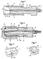
- connection device essentially consists of three parts: first, for each of the two optical fibers to be connected, a tip 1, and then a connection box 2, symmetrical, having in its center a centering sub-assembly 19 and receiving the two end pieces 1.
- a particularity of this connection box 2 is that in the absence of end piece, it is provided with plugs protection 3.
- the connection box carries an end piece 1 and a protective plug 3.
- connection box, the end caps and the protective caps are advantageously made of plastic and produced by injection molding.
- Each end piece 1 is of generally cylindrical shape (FIG. 2), and comprises at the front a cylindrical ring 4 for protecting the end of the fiber 9 and, sliding in the ring, a end piece body 10 with at the rear a cylindrical end 5 of reduced diameter to allow crimping, at 6 on the mechanical coating of the optical cable 7, and at 8 on the optical fiber 9 itself, which is provided with a protective elastomer 50.
- the tip body 10 is provided with an interior chamber 11, traversed longitudinally by the optical fiber 9 which has been stripped, and which projects beyond the end of the tip body 10 d 'a predetermined length.
- the fiber 9 is cut very precisely to a length L from the front end 51.
- the tip body has an annular shoulder 54 on which the arms 53 abut when the ring moves forward, so that, when the ring 4 is in the protective position, the rib 41 being in abutment against the end 51, the ring is immobilized longitudinally and cannot escape from the tip body 10. This position is called "protection locking".
- the ring comprises an elastically deformable arm and provided at its outward end with a pawl 17 for locking on the housing.
- connection box 2 is symmetrical with respect to its median transverse plane. It comprises a cylindrical part 12, intended to receive the end piece 1 whose longitudinal axis is slightly inclined at an angle ⁇ relative to the longitudinal axis of the centering sub-assembly 19. Preferably, this angle is small and of the order of 2 °.
- the fitting of the end piece 1 is carried out as follows:
- the protective ring 4 is inserted in the locked position, in the cylindrical part 12.
- the pawl 17 maintains the ring 4 on the housing 2 and the latter can be unlocked from its position by rotation of the tip body 10.
- the tip body slides inside the latter until the end 51 abuts on the bottom 15, and the pawls 18 then hold the tip body in position connected.
- a connection box 2 according to the invention is fitted with protective plugs 3 on its two inputs after its manufacture. Each of these plugs will not be removed until the fitting of a nozzle. Thus, in the case of FIG. 1, the box 2 has received a single end piece 1, and the plug 13 provides protection for the standby channel.
- each endpiece with respect to the axis of the centering sub-assembly 19 allows the two fibers in contact to end up on the same side of the centering element, which very significantly reduces the axial misalignment due to the differences in the diameter of the optical fibers, as well as differences in concentricity and cylindricity.
- Figure 1 there is shown at 20 the position that would have the fiber 7 if the other tip was in place.
- the centering sub-assembly 19 essentially consists of a cylindrical casing 27 inside which are means for centering the fibers, such as artificial rubies, balls, machined rods, or in V and a liquid 23 index adapter.
- This liquid with an index between 1.4 and 1.5, has a very high viscosity to ensure sufficient retention in the cavity of the centering sub-assembly 19, by the surface tensions.
- This cylindrical envelope 27 is housed in a cavity 22 of the housing 2.
- a lateral opening 46 is made in the housing to set up said cylindrical envelope. This opening allows access to the centering sub-assembly at any time, and to easily replace the sub-assembly in place with another or its elements arranged inside. This opening is closed by a removable plate or the like 47.
- the centering sub-assembly is made up of a tube 27 (FIG. 6), of fixed external diameter to ensure the interchangeability of the sub-assembly, and of centering elements arranged inside the tube.
- These centering elements can be of several kinds.
- two centralizers or synthetic rubies 26, each having an axial passage and a tapered cone face facing outward in order to facilitate guiding the ends of the bare fibers 9, are spaced apart in order to '' admit between them a reserve of liquid 23.
- the support plane 21 bathes the optical faces of the two fibers in connection, and the angle of inclination of the end pieces, therefore of the fiber ensures that the fibers are supported on the same generator.
- FIG. 6 The exemplary embodiment of FIG. 6 is well suited when the fibers have a diameter greater than approximately 85 ⁇ m, that is to say when they are large core fibers.
- the centering sub-assembly of FIG. 7 with four centralizers, the support plane 21 being always in the middle, and two centralizers 26 being provided for each fiber end 9. These two centralizers are identical, offset from each other and separated by the viscous liquid 23 which fills practically all the free space in the tube 27.
- the internal diameter of the centralizers is determined during construction as a function of the diameter of the optical fibers which must be connected.
- the third embodiment of the centering sub-assembly uses a set of eighteen identical centering balls 28 arranged inside the bore 30 of the tube 27.
- the balls are distributed in six layers of three marbles each. In each layer, each ball has a point of contact 29 with the other two. In the center, there is an interstitial space 31 for the passage of the fibers 9.
- Two adjacent layers of balls are offset by 60 ° so that all the layers are fixed and self-centered. Due to the symmetry of the assembly, the fiber 9 can no longer be blocked, during its insertion, in a hypocycloidal space such as 32. In addition, the stacking of the beads being very regular, can be easily automated.
- the support plane 21 of the two fiber ends is located in a zone 33 between the radial median planes of two layers of balls, which ensures the presence of the liquid 23, l angel of inclination ⁇ ensuring a better connection in that the two fibers in contact are on the same side of the space.
- the fourth embodiment uses as centering means, not balls but rods 34 machined, of general shape cylindrical, regularly distributed in the tube 27, with their axes parallel to the axis of the tube 27. Their outer surfaces 35 are in pairs and each contact with the inner surface of the tube, so that in the axis of the tube 27 an interstitial space 36 is provided for the insertion of the optical fibers.
- each rod 34 is provided with three constrictions regularly distributed over the length: one 39 in the middle, and the other two 40 on either side (FIG. 10).
- the space between the three rods and the tube 27 is filled with the adapter liquid of index 23.
- the ends of the rods and the connecting parts between the large diameter parts 37 and the throttles 39, 40 are frustoconical to facilitate the fiber guidance.
- the transverse dimensions of the rods can vary as a function of the outside diameter of the optical fibers to be connected.
- the fifth embodiment uses as a centralized means a longitudinal V43 provided at each end with three balls 28, in order to correctly guide the ball at the time of connection.
- This V is preferably molded, and has a volume 44 of triangular section for retaining the liquid 23 in the connection area.
- the angle of inclination ⁇ allows perfect alignment by the support of the two fibers on the two inclined planes of the V.
- connection box 2 has on its underside a base 24 provided with pawls 25, capable of being fixed on a rail or any other plate, not shown, intended to receive a series of similar boxes 2.
Landscapes
- Physics & Mathematics (AREA)
- General Physics & Mathematics (AREA)
- Optics & Photonics (AREA)
- Mechanical Coupling Of Light Guides (AREA)
Claims (12)
- Verbindungsvorrichtung für optische Fasern, bei der zwei identische Ansatzteile (1) von allgemein rohrförmiger Gestalt zur Aufnahme jeweils einer der zu verbindenden Fasern und ein symmetrisches Verbindungsgehäuse (2), das in seinem Mittelbereich mit einer Unterbaugruppe (19) zum Zentrieren versehen ist, zur beidseitigen Aufnahme der die beiden zu verbindenden Fasern tragenden Ansatzteile vorgesehen sind, wobei jedes Ansatzteil einen ringförmigen Ansatzteil-Körper mit einem ringförmigen, rückseitigen Ende mit verkleinertem Außendurchmesser zum Sicherstellen einer Befestigung an dem Schutzmantel und/oder den Schutzmänteln für die betreffende Faser und ferner einen Ring zur Befestigung auf dem Verbindungsgehäuse sowie eine rohrförmige Schutzeinrichtung für die Faser aufweist, wobei die Schutzeinrichtung am vordere Ende (51) des Ansatzteil-Körpers (10) verschiebbar zwischen einer vorderen Längsposition, in der sie zum Schutz des abgemantelten Faserendes (9) vor der Verbindung dient, und einer rückwärtigen Längsposition, in der sie zum Freilegen des abgemantelten Endes der Faser während des Einsetzens des Ansatzteils (1) in das Verbindungsgehäuse bestimmt ist, angebracht ist, und wobei der genannte Körper mit einer ringförmigen Schulter (54) zur Begrenzung des Ausfahrweges der Schutzeinrichtung in der vorderen Längsposition versehen ist, dadurch gekennzeichnet, daß der Befestigungsring und die Schutzeinrichtung als ein gemeinsames rohrförmiges Teil (4) ausgebildet sind, das beweglich um den Ansatzteil-Körper herum montiert ist und erste Rastmittel (17) zu seiner Befestigung am Verbindungsgehäuse in der Verbindungsposition sowie zweite Rastmittel (18) zum Zusammenwirken mit einer äußeren ringförmigen Rippe (52) des Ansatzteil-Körpers (10) in der rückwärtigen Längsposition des rohrförmigen Teiles derart aufweist, daß dieser Körper in der Verbindungsposition festgehalten wird.
- Verbindungsvorrichtung für optische Fasern nach Anspruch 1, dadurch gekennzeichnet, daß das rohrförmige Schutz/Befestigungsteil (4) mit in rückwärtiger Richtung elastisch verformbaren Armen (53) versehen ist, die nach innen weisende Rasten (18) aufweisen, welche einerseits geeignet sind, in der rückwärtigen Längsposition mit der Rippe (52) zusammenzuwirken, und andererseits in der vorderen Längsposition an der Schulter (54) zur Anlage bringbar sind, wobei diese Resten (18) die zweiten Rastmittel bilden.
- Vorrichtung nach Anspruch 1, dadurch gekennzeichnet, daß das rohrförmige Schutz/Bestigungsteil (4) in seinem Inneren eine Längsrippe (41) zum Gleiten in einer entsprechenden Längsnut (42) aufweist, die vorne am Ansetzteil-Körper (10) auf dessen Außenumfang ausgebildet ist.
- Vorrichtung nach Anspruch 2, bei der das Verbindungsgehäuse (2) eine zylindrische Ausnehmung (12) zur Aufnehme des Ansatzteils (1) aufweist, die sich in einem konischen Teil (16) und einem axialen, in die Unterbaugruppe zum Zentrieren mündenden Durchgang (45) fortsetzt, dadurch gekennzeichnet, daß der Ansatzstück-Körper (10) in Anschlag gegen die Bodenwand (15) der zylindrischen Aussparung (12) bringbar ist und der axiale Durchgang (45) einen verkleinerten Durchmesser aufweist, durch den nur eine einzige abgemantelte Faser hindurchlaufen kann.
- Vorrichtung nach Anspruch 4, dadurch gekennzeichnet, daß die Längsachse der zylindrischen Aussparung (12) um einen kleinen Winkel gegenüber der Längsachse der Unterbaugruppe (19) zum Zentrieren geneigt ist.
- Vorrichtung nach Anspruch 5, dadurch gekennzeichnet, daß der Nejgungswinkel (α) in der Größenordnung von 2° ist.
- Vorrichtung nach Anspruch 1, bei der das Verbindungsgehäuse eine zum Unterbringen der Unterbaugruppe zum Zentrieren bestimmte Ausnehmung aufweist, dadurch gekennzeichnet, daß das Gehäuse (2) seitlich eine Öffnung (46) zum Einführen dieser Unterbaugruppe ausbildet.
- Vorrichtung nach Anspruch 1, dadurch gekennzeichnet, daß die Unterbaugruppe (19) zum Zentrieren mechanische Zentriermittel und eine viskose Adapterflüssigkeit (23) für eine Anzeige aufweist.
- Vorrichtung nach Anspruch 8, dadurch gekennzeichnet, daß die Zentriermittel von drei bearbeiteten Stäben (34) einer im wesentlichen zylindrischen Form gebildet sind, die mit Querschnittseinschnürungen (39, 40) versehen sind.
- Vorrichtung nach Anspruch 9, dadurch gekennzeichnet daß die Stäbe (34) konische Enden zur Führung der Fasern (9) und zum Zurückhalten der Adapterflüssigkeit (23) für die Anzeige aufweisen.
- Vorrichtung nach Anspruch 8, dadurch gekennzeichnet, daß die Zentriermittel von einer Form-Längsnut mit V-förmigem Querschnitt (43) gebildet werden, bei der an jedem Ende drei Kugeln zur Führung der Faser in dem V angebracht sind.
- Vorrichtung nach Anspruch 1, dadurch gekennzeichnet, daß das Verbindungsgehäuse (2) unten einen Ansatz (24) aufweist, der mit geeigneten Rasten (25) zur Befestigung auf einem schienenförmigen Träger für die Aufnahme einer Reihe von Gehäusen versehen ist.
Applications Claiming Priority (2)
| Application Number | Priority Date | Filing Date | Title |
|---|---|---|---|
| FR8701252 | 1987-02-03 | ||
| FR8701252A FR2610419B1 (fr) | 1987-02-03 | 1987-02-03 | Dispositif de connexion pour fibres optiques |
Publications (3)
| Publication Number | Publication Date |
|---|---|
| EP0277878A2 EP0277878A2 (de) | 1988-08-10 |
| EP0277878A3 EP0277878A3 (en) | 1990-05-30 |
| EP0277878B1 true EP0277878B1 (de) | 1994-10-12 |
Family
ID=9347514
Family Applications (1)
| Application Number | Title | Priority Date | Filing Date |
|---|---|---|---|
| EP19880400219 Expired - Lifetime EP0277878B1 (de) | 1987-02-03 | 1988-02-01 | Verbindungsvorrichtung für optische Fasern |
Country Status (3)
| Country | Link |
|---|---|
| EP (1) | EP0277878B1 (de) |
| DE (1) | DE3851765T2 (de) |
| FR (1) | FR2610419B1 (de) |
Families Citing this family (4)
| Publication number | Priority date | Publication date | Assignee | Title |
|---|---|---|---|---|
| US8985867B2 (en) | 2011-09-07 | 2015-03-24 | Adc Telecommunications, Inc. | Optical fiber connection system |
| US8985864B2 (en) | 2011-09-07 | 2015-03-24 | Adc Telecommunications, Inc. | Optical fiber alignment device and method |
| EP2753962A4 (de) * | 2011-09-07 | 2015-08-19 | Adc Telecommunications Inc | Glasfaserverbindungssystem |
| US8979395B2 (en) | 2011-09-07 | 2015-03-17 | Adc Telecommunications, Inc. | Tools and methods for preparing a ferrule-less optical fiber connector |
Family Cites Families (6)
| Publication number | Priority date | Publication date | Assignee | Title |
|---|---|---|---|---|
| NL7802230A (nl) * | 1978-03-01 | 1979-09-04 | Tekade Felten & Guilleaume | Losneembare stekkerverbinding, alsmede stekker en con- trastekker voor het koppelen van een lichtgeleidende vezel aan een verdere lichtgeleidende vezel of aan een lichtbron/detektor. |
| CA1093873A (en) * | 1978-06-05 | 1981-01-20 | Helmut H. Lukas | Optical fibre connector |
| EP0009211B1 (de) * | 1978-09-20 | 1986-07-23 | Nippon Telegraph And Telephone Corporation | Justiermechanismus für Lichtleiter und ihn verwendender Verbinder |
| FR2469725A1 (fr) * | 1979-11-08 | 1981-05-22 | Lyonnaise Transmiss Optiques | Connecteur pour fibres optiques |
| US4378145A (en) * | 1980-03-03 | 1983-03-29 | Thomas & Betts Corporation | Method and apparatus for joining optical elements |
| CH640354A5 (fr) * | 1981-03-24 | 1983-12-30 | Seitz Sa | Centreur pour connecteur de fibres optiques. |
-
1987
- 1987-02-03 FR FR8701252A patent/FR2610419B1/fr not_active Expired - Lifetime
-
1988
- 1988-02-01 EP EP19880400219 patent/EP0277878B1/de not_active Expired - Lifetime
- 1988-02-01 DE DE19883851765 patent/DE3851765T2/de not_active Expired - Fee Related
Also Published As
| Publication number | Publication date |
|---|---|
| FR2610419B1 (fr) | 1991-08-30 |
| FR2610419A1 (fr) | 1988-08-05 |
| DE3851765T2 (de) | 1995-06-08 |
| EP0277878A2 (de) | 1988-08-10 |
| EP0277878A3 (en) | 1990-05-30 |
| DE3851765D1 (de) | 1994-11-17 |
Similar Documents
| Publication | Publication Date | Title |
|---|---|---|
| EP0097575B1 (de) | Stecker für faseroptisches Verbindungsstück und Verbindungsstück mit solchem Stecker | |
| EP0462907B1 (de) | Faseroptischer Stecker mit schneller Verriegelung und Entriegelung | |
| EP0008329B1 (de) | Vorrichtung zum Verbinden optischer Fasern | |
| EP0051519B1 (de) | Zwinge für einen Verbinder für optische Fasern und Verbinder mit einer solchen Zwinge | |
| FR2477290A1 (fr) | Procede et appareil pour joindre des elements optiques tels que des fibres optiques | |
| FR2553199A1 (fr) | Connecteur de fibres optiques | |
| FR2485754A1 (fr) | Connecteur de fibres optiques | |
| EP2793063B1 (de) | Adapter mit Haltekäfig für einen Multikontakt-Steckverbinder und entsprechender Multikontakt-Steckverbinder | |
| FR2699689A1 (fr) | Connecteur de fibres optiques. | |
| FR2748576A1 (fr) | Dispositif pour lover des rubans ou des micro-gaines de fibres optiques, et leurs epissures ou coupleurs de raccordement | |
| EP0051510A1 (de) | Einrichtung für die optische Fasereinstellung in einer aus einem Stück gebildeten Zwinge zum Verbinden von zwei Transmissionskabeln mittels optischer Fasern | |
| FR2466028A1 (fr) | Connecteurs pour fibres optiques | |
| EP0277878B1 (de) | Verbindungsvorrichtung für optische Fasern | |
| FR2588387A1 (fr) | Element de connecteur hermaphrodite pour fibres optiques | |
| FR2564986A1 (fr) | Element de connecteur hermaphrodite pour cable optique | |
| EP0014610A1 (de) | Lösbare Verbindungsvorrichtung für optische Fasern | |
| FR2517437A1 (fr) | Connecteur de fibres optiques | |
| EP0036369B1 (de) | Verfahren und Vorrichtung zum Verbinden faseroptischer Kabel auf dem Arbeitsplatz | |
| WO1992002836A1 (fr) | Connecteur pour fibres optiques | |
| FR2645615A1 (fr) | Dispositif de raccordement reglable | |
| FR2530829A1 (fr) | Connecteur de fibres optiques | |
| EP0098190B1 (de) | Vorrichtung zum Verbinden und zum Ausrichten zweier faseroptischen Verbindungsstecker mit einem V-förmigen Querschnitt | |
| EP0068423B1 (de) | Verbindung für optische Monofasern | |
| EP0263739B1 (de) | Stecker für optische Fasern | |
| FR2774181A1 (fr) | Dispositif de connexion/deconnexion de deux fibres optiques individuelles et epanouisseur-connecteur pour fibres optiques |
Legal Events
| Date | Code | Title | Description |
|---|---|---|---|
| PUAI | Public reference made under article 153(3) epc to a published international application that has entered the european phase |
Free format text: ORIGINAL CODE: 0009012 |
|
| AK | Designated contracting states |
Kind code of ref document: A2 Designated state(s): DE GB |
|
| 17P | Request for examination filed |
Effective date: 19880805 |
|
| PUAL | Search report despatched |
Free format text: ORIGINAL CODE: 0009013 |
|
| AK | Designated contracting states |
Kind code of ref document: A3 Designated state(s): DE GB |
|
| 17Q | First examination report despatched |
Effective date: 19921105 |
|
| GRAA | (expected) grant |
Free format text: ORIGINAL CODE: 0009210 |
|
| AK | Designated contracting states |
Kind code of ref document: B1 Designated state(s): DE GB |
|
| REF | Corresponds to: |
Ref document number: 3851765 Country of ref document: DE Date of ref document: 19941117 |
|
| GBT | Gb: translation of ep patent filed (gb section 77(6)(a)/1977) |
Effective date: 19950106 |
|
| PLBE | No opposition filed within time limit |
Free format text: ORIGINAL CODE: 0009261 |
|
| STAA | Information on the status of an ep patent application or granted ep patent |
Free format text: STATUS: NO OPPOSITION FILED WITHIN TIME LIMIT |
|
| 26N | No opposition filed | ||
| PGFP | Annual fee paid to national office [announced via postgrant information from national office to epo] |
Ref country code: GB Payment date: 19990204 Year of fee payment: 12 |
|
| PGFP | Annual fee paid to national office [announced via postgrant information from national office to epo] |
Ref country code: DE Payment date: 19990429 Year of fee payment: 12 |
|
| PG25 | Lapsed in a contracting state [announced via postgrant information from national office to epo] |
Ref country code: GB Free format text: LAPSE BECAUSE OF NON-PAYMENT OF DUE FEES Effective date: 20000201 |
|
| GBPC | Gb: european patent ceased through non-payment of renewal fee |
Effective date: 20000201 |
|
| PG25 | Lapsed in a contracting state [announced via postgrant information from national office to epo] |
Ref country code: DE Free format text: LAPSE BECAUSE OF NON-PAYMENT OF DUE FEES Effective date: 20001201 |