EP0051519B1 - Zwinge für einen Verbinder für optische Fasern und Verbinder mit einer solchen Zwinge - Google Patents
Zwinge für einen Verbinder für optische Fasern und Verbinder mit einer solchen Zwinge Download PDFInfo
- Publication number
- EP0051519B1 EP0051519B1 EP81401660A EP81401660A EP0051519B1 EP 0051519 B1 EP0051519 B1 EP 0051519B1 EP 81401660 A EP81401660 A EP 81401660A EP 81401660 A EP81401660 A EP 81401660A EP 0051519 B1 EP0051519 B1 EP 0051519B1
- Authority
- EP
- European Patent Office
- Prior art keywords
- socket
- sleeve
- centering
- centering sleeve
- connector
- Prior art date
- Legal status (The legal status is an assumption and is not a legal conclusion. Google has not performed a legal analysis and makes no representation as to the accuracy of the status listed.)
- Expired
Links
Images
Classifications
-
- G—PHYSICS
- G02—OPTICS
- G02B—OPTICAL ELEMENTS, SYSTEMS OR APPARATUS
- G02B6/00—Light guides; Structural details of arrangements comprising light guides and other optical elements, e.g. couplings
- G02B6/24—Coupling light guides
- G02B6/36—Mechanical coupling means
- G02B6/38—Mechanical coupling means having fibre to fibre mating means
- G02B6/3807—Dismountable connectors, i.e. comprising plugs
- G02B6/3873—Connectors using guide surfaces for aligning ferrule ends, e.g. tubes, sleeves, V-grooves, rods, pins, balls
- G02B6/3874—Connectors using guide surfaces for aligning ferrule ends, e.g. tubes, sleeves, V-grooves, rods, pins, balls using tubes, sleeves to align ferrules
- G02B6/3875—Floatingly supported sleeves
-
- G—PHYSICS
- G02—OPTICS
- G02B—OPTICAL ELEMENTS, SYSTEMS OR APPARATUS
- G02B6/00—Light guides; Structural details of arrangements comprising light guides and other optical elements, e.g. couplings
- G02B6/24—Coupling light guides
- G02B6/36—Mechanical coupling means
- G02B6/38—Mechanical coupling means having fibre to fibre mating means
- G02B6/3807—Dismountable connectors, i.e. comprising plugs
- G02B6/381—Dismountable connectors, i.e. comprising plugs of the ferrule type, e.g. fibre ends embedded in ferrules, connecting a pair of fibres
- G02B6/3818—Dismountable connectors, i.e. comprising plugs of the ferrule type, e.g. fibre ends embedded in ferrules, connecting a pair of fibres of a low-reflection-loss type
- G02B6/3821—Dismountable connectors, i.e. comprising plugs of the ferrule type, e.g. fibre ends embedded in ferrules, connecting a pair of fibres of a low-reflection-loss type with axial spring biasing or loading means
-
- G—PHYSICS
- G02—OPTICS
- G02B—OPTICAL ELEMENTS, SYSTEMS OR APPARATUS
- G02B6/00—Light guides; Structural details of arrangements comprising light guides and other optical elements, e.g. couplings
- G02B6/24—Coupling light guides
- G02B6/36—Mechanical coupling means
- G02B6/38—Mechanical coupling means having fibre to fibre mating means
- G02B6/3807—Dismountable connectors, i.e. comprising plugs
- G02B6/381—Dismountable connectors, i.e. comprising plugs of the ferrule type, e.g. fibre ends embedded in ferrules, connecting a pair of fibres
- G02B6/3825—Dismountable connectors, i.e. comprising plugs of the ferrule type, e.g. fibre ends embedded in ferrules, connecting a pair of fibres with an intermediate part, e.g. adapter, receptacle, linking two plugs
Definitions
- the present invention relates to a connector for an optical fiber connector, comprising at least one centering sleeve of substantially cylindrical shape in which an optical fiber is fixed, said centering sleeve having at its front end a contact face where the fiber opens out and at near its rear end means for positioning the centering sleeve in the end piece, as well as means for orienting the centering sleeve.
- Fiber optic connectors made with such tips have a number of drawbacks.
- the corresponding end pieces must be produced with very high precision by machining, which necessarily leads to high manufacturing costs.
- an alignment of the fibers is necessary using corresponding screws in order to obtain a minimum attenuation of the information transmitted by the connector. Such an operation is necessarily long and tedious.
- such tips cannot be used for the simultaneous connection of several optical channels. Indeed, the very small adjustment tolerances necessary for the connection of two end pieces are further reduced when it is desired to ensure the simultaneous connection of several end pieces, and it is not currently possible to manufacture multi-fiber optic connectors. tracks using these tips and having acceptable performance.
- the ferrules for optical fiber connectors according to the invention make it possible to avoid these drawbacks.
- the subject of the present invention is a tip for an optical fiber connector carrying at least one centering sleeve of substantially cylindrical shape, in which an optical fiber is fixed, said centering sleeve having at its anterior end a contact face where opens the fiber and near its rear end means for positioning the centering sleeve in the end piece, as well as means for orienting the centering sleeve, characterized in that said means for orienting the centering sleeve are constituted by a ball-forming device arranged between the means for positioning the centering sleeve and the rear end of the end-piece, the latter allowing the sleeve to pivot inside said end-piece, around the pivot point of the ball-forming device.
- the ball-forming device is constituted by a circular groove hollowed out in the centering sleeve cooperating with an O-ring housed therein and bearing on the corresponding internal housing of the end piece.
- such a nozzle has the advantage of being waterproof when the O-ring used is elastic, which makes it possible to use this nozzle for the connection of optical fibers in a liquid medium. There is then no risk of liquid rising in the sheath of the optical cable.
- the positioning means which are arranged between the ball-forming device and the front end of the end piece are constituted by a disc provided with a central channel, the two outer and inner base surfaces of which cooperate respectively with the shoulders carried by the connector end piece and the centering sleeve which is housed therein, said disc being fixed with transverse play in the 'tip while ensuring translation locking.
- these positioning means must have dimensions such that the pivoting of the centering sleeve around the ball-forming device is located inside a cone having an opening angle of the order of 1 °.
- a coupling sleeve such as that preferably is used which is described in French patent application No. 80 06 613 in the name of the Applicant.
- the end piece according to the invention be in the form of a female end piece, it suffices to provide the centering sleeve with a coupling sleeve, such as that to which reference is made above. above.
- this coupling sleeve will be held in the endpiece by attached parts fixed thereto and thus avoiding the separation of said sleeves.
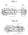
- a fiber 2, provided with its protective sheath 3, is housed in the cylindrical centering sleeve 4, pierced with a longitudinal axial channel, where it is fixed after stripping, by a known means, such as a polymerizable adhesive; this fixing may advantageously have been made in the workshop, on a mounting device ensuring the concentricity between the fiber 2 and the cylindrical outer surface 5 of the centering sleeve 4 during the polymerization.
- the centering sleeve opens the contact face 6 of the fiber, surrounded by a chamfer 7 in the form of a cone of revolution.
- the entire sleeve can move longitudinally in the tip of the connector 1 which supports it.
- the opening of the connector 1 through which the centering sleeve passes is slightly larger in diameter than the latter. This allows lateral play of said sleeve during coupling (vertical movement in the figure).
- the part (A) described above therefore has the property of allowing both a longitudinal and lateral movement of the centering sleeve which allows, in particular in the case of simultaneous multi-path coupling, to avoid the stresses between the sleeves centering and the coupling sleeve, which allows a good alignment of the fibers.
- Part (B) which can be designated, by way of simplification, under the name of "female part”, represents a nozzle according to the invention.
- the centering sleeve 24 carries a coupling sleeve 27, in the form of a tube, the internal diameter of the free projecting part 28 of which is chosen to be slightly smaller than the external diameter of the centering end piece 4.
- a typical embodiment of this coupling sleeve consists, by adopting the same external diameter for the two centering sleeves 4 and 24 of the parts (A) and (B), in constituting it with a tube made of elastic material, provided a longitudinal slot, and making a tightening on the sleeves when introduced therein.
- the centering sleeve 24 is fixed in the end piece 21 by a disc-shaped means 29, the sleeve being held there longitudinally by shoulders bearing on the lateral faces of this disc, carried respectively by the sleeve and the end piece .
- a seal constituted by an elastic ring 30 of toric shape, is disposed at the opposite end, or posterior, to the entry face of the end piece, in a groove 31 carried by the sleeve of centering.
- this elastic ring assumes, in combination with its function of angular pivot center of the centering sleeve 24, a sealing function.
- the invention provides for allowing the pivoting of the centering sleeve 24 around the center 51 located substantially in the median plane of the O-ring, by providing a "clearance" 32 between the lateral cylindrical surfaces, respectively external and internal, disc 29 and its housing in the nozzle; as a typical order of magnitude, the pivoting chosen can be ⁇ 1 ° relative to the axis.
- Figure 2 shows the two parts (A) and (B), in the connected position.
- this sheath has at its inlet 41 a guide cone 42, the external and internal diameters of which are determined to compensate for the differences in alignment of the centering sleeves, in particular for multi-way connectors.
- FIGS. 1 and 2 the presence of a semi-spherical joint 50 on the spherical part of which the coupling sleeve 27 is supported during its rotation operation possible around the pivot point 51 of the ball joint.
- This seal 50 is provided with a central channel through which the centering sleeve 24 passes.
- the spherical face of this seal 50 has a radius of curvature R whose center is the pivot point 51 of the ball joint.
- the full face of the seal 50 rests on two shoulders 52 and 53 carried by the end piece (B). During the connection of A and B, this avoids the stresses of the centering and coupling sleeves one on the other which facilitates the connection and the self-alignment of the fibers.
- the implementation of the male-female assembly according to the invention has made it possible to verify the possibility of connection of two optical fibers with an attenuation less than or equal to 0.5 dB at the connection level in the case of the simultaneous connection of six optical channels.
- the coupling sleeve described above consists of a tube of elastic material, provided with a longitudinal slot.
- a sleeve will be used as described in French patent application No. 80 06 613 consisting of a cylindrical part in the form of a tube, comprising a plurality of longitudinal clamping jaws, regularly distributed around the periphery of the tube.
Claims (16)
Applications Claiming Priority (2)
| Application Number | Priority Date | Filing Date | Title |
|---|---|---|---|
| FR8023391A FR2493535A1 (fr) | 1980-10-31 | 1980-10-31 | Embout pour connecteur de fibre optique et connecteur muni d'un tel embout |
| FR8023391 | 1980-10-31 |
Publications (2)
| Publication Number | Publication Date |
|---|---|
| EP0051519A1 EP0051519A1 (de) | 1982-05-12 |
| EP0051519B1 true EP0051519B1 (de) | 1987-07-15 |
Family
ID=9247572
Family Applications (1)
| Application Number | Title | Priority Date | Filing Date |
|---|---|---|---|
| EP81401660A Expired EP0051519B1 (de) | 1980-10-31 | 1981-10-21 | Zwinge für einen Verbinder für optische Fasern und Verbinder mit einer solchen Zwinge |
Country Status (6)
| Country | Link |
|---|---|
| US (1) | US4445753A (de) |
| EP (1) | EP0051519B1 (de) |
| JP (1) | JPS57104912A (de) |
| CA (1) | CA1179877A (de) |
| DE (1) | DE3176316D1 (de) |
| FR (1) | FR2493535A1 (de) |
Families Citing this family (24)
| Publication number | Priority date | Publication date | Assignee | Title |
|---|---|---|---|---|
| DE3215879A1 (de) * | 1982-04-29 | 1983-11-03 | Fa. Carl Zeiss, 7920 Heidenheim | Geraet zur spektrenmessung in der blutbahn |
| FR2529349A1 (fr) * | 1982-06-25 | 1983-12-30 | Souriau & Cie | Connecteur de fibre optique pour support coulissant dans une armoire ratelier |
| FR2531544B1 (fr) * | 1982-08-04 | 1985-01-25 | Cit Alcatel | Tete de cable optique |
| DE8225781U1 (de) * | 1982-09-13 | 1982-12-09 | Siemens AG, 1000 Berlin und 8000 München | Fuehrungshuelse fuer lichtwellenleitersteckvorrichtungen |
| JPS59170809U (ja) * | 1983-04-30 | 1984-11-15 | 株式会社島津製作所 | 光コネクタ |
| JPS60172107U (ja) * | 1984-04-23 | 1985-11-14 | ヒロセ電機株式会社 | 光フアイバ心線用コネクタ |
| US4687291A (en) * | 1984-06-08 | 1987-08-18 | Amp Incorporated | Duplex electro-fiber connector assembly |
| US4723830A (en) * | 1984-06-22 | 1988-02-09 | Eastman Kodak Company | Optical fiber connectors |
| US4729619A (en) * | 1986-05-01 | 1988-03-08 | Minnesota Mining And Manufacturing Company | Optical fiber connector incorporating means for isolating connection from external stresses |
| JPS6336210A (ja) * | 1986-07-29 | 1988-02-16 | ジ−メンス・アクチエンゲゼルシヤフト | 光波導体差込み結合部材を備えた装置 |
| DE3704070A1 (de) * | 1987-02-10 | 1988-08-18 | Spinner Gmbh Elektrotech | Lwl-einschubsteckverbindung |
| US4773724A (en) * | 1987-04-13 | 1988-09-27 | Mcdonnell Douglas Corporation | Packaging for fiber optic devices |
| DK158169C (da) * | 1987-08-31 | 1990-09-03 | Dantec Elektronik Med | Indkoblingsmanipulator for laserlys til en optisk fiber |
| US4807957A (en) * | 1987-10-15 | 1989-02-28 | Siecor Corporation | Connector for optical fibers |
| US4812007A (en) * | 1987-12-07 | 1989-03-14 | Northern Telecom Limited | Optical fiber connector |
| US5142600A (en) * | 1991-02-25 | 1992-08-25 | General Electric Company | Optical fiber quick connect/disconnect for a power laser |
| JP2978585B2 (ja) * | 1991-04-17 | 1999-11-15 | 本多通信工業株式会社 | 光ファイバコネクタ用フェルール |
| US5563971A (en) * | 1995-04-28 | 1996-10-08 | The Whitaker Corporation | Floating bottleneck for multiple position fiber optic receptacle |
| US7422376B2 (en) * | 1999-12-07 | 2008-09-09 | Molex Incorporated | Self-contained fiber optic connector module |
| US6490868B1 (en) | 2000-08-17 | 2002-12-10 | Siemens Westinghouse Power Corporation | Adjustable mounting device for aligning optical sensor in gas turbine engine combustor |
| DE10124028B4 (de) * | 2001-05-16 | 2010-02-18 | 3M Espe Ag | Selbstadhäsive Dentalmaterialien |
| US6811322B2 (en) * | 2002-10-24 | 2004-11-02 | Molex Incorporated | Fiber optic connector module |
| DE202004020043U1 (de) * | 2004-12-22 | 2006-02-09 | CCS Technology, Inc., Wilmington | Lichtwellenleiteranschlusseinrichtung, Stecker und Steckverbindung für Lichtwellenleiter |
| US8337093B2 (en) * | 2009-09-30 | 2012-12-25 | Corning Cable Systems Llc | Fiber optic connectors and methods for making the same |
Family Cites Families (7)
| Publication number | Priority date | Publication date | Assignee | Title |
|---|---|---|---|---|
| JPS5249039A (en) * | 1975-10-16 | 1977-04-19 | Sumitomo Electric Ind Ltd | Connector for optical fibers |
| US4124272A (en) * | 1976-12-14 | 1978-11-07 | Westinghouse Electric Corp. | Rotary fiber optic waveguide coupling |
| FR2379079A1 (fr) * | 1977-01-28 | 1978-08-25 | Connexion Ste Nle | Connecteur a elements auto-centreurs pour conducteurs optiques |
| US4193664A (en) * | 1977-03-11 | 1980-03-18 | International Standard Electric Corporation | Optical fiber connector |
| GB1571942A (en) * | 1977-03-24 | 1980-07-23 | Cannon Electric Great Britain | Fibre optic connector |
| FR2408152A1 (fr) * | 1978-10-03 | 1979-06-01 | Bunker Ramo | Dispositif et procede pour aligner des fibres optiques dans un connecteur |
| DE2922937C2 (de) * | 1979-06-01 | 1981-07-02 | Fabeg Gmbh, 7518 Bretten | Kabelkupplung zum selbsttätigen Durchkuppeln elektrischer Heiz- und/oder Steuerstromleitungen sowie von Lichtleitern zur optischen Befehlsübertragung, insbesondere für Bahnfahrzeuge |
-
1980
- 1980-10-31 FR FR8023391A patent/FR2493535A1/fr active Granted
-
1981
- 1981-10-21 DE DE8181401660T patent/DE3176316D1/de not_active Expired
- 1981-10-21 EP EP81401660A patent/EP0051519B1/de not_active Expired
- 1981-10-26 US US06/315,268 patent/US4445753A/en not_active Expired - Lifetime
- 1981-10-27 CA CA000388785A patent/CA1179877A/en not_active Expired
- 1981-10-30 JP JP56174353A patent/JPS57104912A/ja active Pending
Also Published As
| Publication number | Publication date |
|---|---|
| FR2493535B1 (de) | 1984-02-24 |
| FR2493535A1 (fr) | 1982-05-07 |
| JPS57104912A (en) | 1982-06-30 |
| EP0051519A1 (de) | 1982-05-12 |
| CA1179877A (en) | 1984-12-27 |
| DE3176316D1 (en) | 1987-08-20 |
| US4445753A (en) | 1984-05-01 |
Similar Documents
| Publication | Publication Date | Title |
|---|---|---|
| EP0051519B1 (de) | Zwinge für einen Verbinder für optische Fasern und Verbinder mit einer solchen Zwinge | |
| EP0008329B1 (de) | Vorrichtung zum Verbinden optischer Fasern | |
| EP0131488B1 (de) | Optische Verbindung und Verfahren zu ihrer Herstellung sowie Faser-Faser, Faser-Diode-Verbindungen die sich aus dieser Verbindung ergeben | |
| CA1131952A (fr) | Connecteur pour liaison a fibre optique | |
| EP0441676B1 (de) | Stecker für optische Fasern | |
| CA1123243A (fr) | Connecteur pour fibres optiques et dispositif de montage des fibres sur des embouts directement utilisables sur connecteur | |
| EP0063085B1 (de) | Verbinder für optische Fasern und Verfahren zu seiner Herstellung | |
| FR2504279A1 (fr) | Appareil d'alignement d'une fibre optique avec une lentille collimatrice | |
| FR2553199A1 (fr) | Connecteur de fibres optiques | |
| EP0462907A1 (de) | Faseroptischer Stecker mit schneller Verriegelung und Entriegelung | |
| FR2672696A1 (fr) | Raccord pour l'interconnexion de deux fibres optiques. | |
| FR2485754A1 (fr) | Connecteur de fibres optiques | |
| CA1087007A (fr) | Connecteur pour liaison a fibre optique | |
| EP0246165B1 (de) | Steckerhülse für polarisationserhaltende Monomodefaser und ihr Justierverfahren | |
| FR2588387A1 (fr) | Element de connecteur hermaphrodite pour fibres optiques | |
| FR2591761A1 (fr) | Ensemble de collimation deconnectable | |
| EP2491446B1 (de) | Lichtwellenleitersteckvorrichtung | |
| EP0036369A1 (de) | Verfahren und Vorrichtung zum Verbinden faseroptischer Kabel auf dem Arbeitsplatz | |
| FR2530829A1 (fr) | Connecteur de fibres optiques | |
| EP0034987A1 (de) | Verbindungsvorrichtung für optische Fasern | |
| EP0051507A1 (de) | Verbindungs- und Anpassungseinrichtung für zwei Verbinderzwingen für optische Fasern und Verbinder für eine solche Einrichtung | |
| EP0478460B1 (de) | Alveolarstecker mit mindestens einer optischen Steckverbindung | |
| EP0277878B1 (de) | Verbindungsvorrichtung für optische Fasern | |
| EP0483338B1 (de) | Optisches verbindungssystem zur anwendung in der übertragung von video-signalen | |
| FR2528587A1 (fr) | Dispositif pour l'application l'une contre l'autre des tranches de deux fibres optiques dans le prolongement l'une de l'autre |
Legal Events
| Date | Code | Title | Description |
|---|---|---|---|
| PUAI | Public reference made under article 153(3) epc to a published international application that has entered the european phase |
Free format text: ORIGINAL CODE: 0009012 |
|
| AK | Designated contracting states |
Designated state(s): BE DE GB IT NL SE |
|
| 17P | Request for examination filed |
Effective date: 19820616 |
|
| GRAA | (expected) grant |
Free format text: ORIGINAL CODE: 0009210 |
|
| AK | Designated contracting states |
Kind code of ref document: B1 Designated state(s): BE DE GB IT NL SE |
|
| PG25 | Lapsed in a contracting state [announced via postgrant information from national office to epo] |
Ref country code: NL Effective date: 19870715 Ref country code: IT Free format text: LAPSE BECAUSE OF FAILURE TO SUBMIT A TRANSLATION OF THE DESCRIPTION OR TO PAY THE FEE WITHIN THE PRESCRIBED TIME-LIMIT;WARNING: LAPSES OF ITALIAN PATENTS WITH EFFECTIVE DATE BEFORE 2007 MAY HAVE OCCURRED AT ANY TIME BEFORE 2007. THE CORRECT EFFECTIVE DATE MAY BE DIFFERENT FROM THE ONE RECORDED. Effective date: 19870715 |
|
| PG25 | Lapsed in a contracting state [announced via postgrant information from national office to epo] |
Ref country code: SE Effective date: 19870731 |
|
| REF | Corresponds to: |
Ref document number: 3176316 Country of ref document: DE Date of ref document: 19870820 |
|
| PG25 | Lapsed in a contracting state [announced via postgrant information from national office to epo] |
Ref country code: BE Effective date: 19871031 |
|
| NLV1 | Nl: lapsed or annulled due to failure to fulfill the requirements of art. 29p and 29m of the patents act | ||
| BERE | Be: lapsed |
Owner name: SOCAPEX Effective date: 19871031 |
|
| PLBE | No opposition filed within time limit |
Free format text: ORIGINAL CODE: 0009261 |
|
| STAA | Information on the status of an ep patent application or granted ep patent |
Free format text: STATUS: NO OPPOSITION FILED WITHIN TIME LIMIT |
|
| 26N | No opposition filed | ||
| PGFP | Annual fee paid to national office [announced via postgrant information from national office to epo] |
Ref country code: DE Payment date: 19890608 Year of fee payment: 8 |
|
| PG25 | Lapsed in a contracting state [announced via postgrant information from national office to epo] |
Ref country code: GB Effective date: 19891021 |
|
| GBPC | Gb: european patent ceased through non-payment of renewal fee | ||
| PG25 | Lapsed in a contracting state [announced via postgrant information from national office to epo] |
Ref country code: DE Effective date: 19900703 |