EP0277408A2 - Extrusion of curved products - Google Patents
Extrusion of curved products Download PDFInfo
- Publication number
- EP0277408A2 EP0277408A2 EP87305870A EP87305870A EP0277408A2 EP 0277408 A2 EP0277408 A2 EP 0277408A2 EP 87305870 A EP87305870 A EP 87305870A EP 87305870 A EP87305870 A EP 87305870A EP 0277408 A2 EP0277408 A2 EP 0277408A2
- Authority
- EP
- European Patent Office
- Prior art keywords
- extrudate
- extrusion
- banana
- products
- stream
- Prior art date
- Legal status (The legal status is an assumption and is not a legal conclusion. Google has not performed a legal analysis and makes no representation as to the accuracy of the status listed.)
- Withdrawn
Links
Images

Classifications
-
- A—HUMAN NECESSITIES
- A23—FOODS OR FOODSTUFFS; TREATMENT THEREOF, NOT COVERED BY OTHER CLASSES
- A23G—COCOA; COCOA PRODUCTS, e.g. CHOCOLATE; SUBSTITUTES FOR COCOA OR COCOA PRODUCTS; CONFECTIONERY; CHEWING GUM; ICE-CREAM; PREPARATION THEREOF
- A23G3/00—Sweetmeats; Confectionery; Marzipan; Coated or filled products
- A23G3/02—Apparatus specially adapted for manufacture or treatment of sweetmeats or confectionery; Accessories therefor
- A23G3/20—Apparatus for coating or filling sweetmeats or confectionery
- A23G3/2007—Manufacture of filled articles, composite articles, multi-layered articles
- A23G3/2015—Manufacture of filled articles, composite articles, multi-layered articles the material being shaped at least partially by a die; Extrusion of filled or multi-layered cross-sections or plates, optionally with the associated cutting device
-
- A—HUMAN NECESSITIES
- A23—FOODS OR FOODSTUFFS; TREATMENT THEREOF, NOT COVERED BY OTHER CLASSES
- A23G—COCOA; COCOA PRODUCTS, e.g. CHOCOLATE; SUBSTITUTES FOR COCOA OR COCOA PRODUCTS; CONFECTIONERY; CHEWING GUM; ICE-CREAM; PREPARATION THEREOF
- A23G3/00—Sweetmeats; Confectionery; Marzipan; Coated or filled products
- A23G3/02—Apparatus specially adapted for manufacture or treatment of sweetmeats or confectionery; Accessories therefor
- A23G3/0236—Shaping of liquid, paste, powder; Manufacture of moulded articles, e.g. modelling, moulding, calendering
- A23G3/0242—Apparatus in which the material is shaped at least partially by a die; Extrusion of cross-sections or plates, optionally the associated cutting device
-
- A—HUMAN NECESSITIES
- A23—FOODS OR FOODSTUFFS; TREATMENT THEREOF, NOT COVERED BY OTHER CLASSES
- A23G—COCOA; COCOA PRODUCTS, e.g. CHOCOLATE; SUBSTITUTES FOR COCOA OR COCOA PRODUCTS; CONFECTIONERY; CHEWING GUM; ICE-CREAM; PREPARATION THEREOF
- A23G3/00—Sweetmeats; Confectionery; Marzipan; Coated or filled products
- A23G3/34—Sweetmeats, confectionery or marzipan; Processes for the preparation thereof
- A23G3/50—Sweetmeats, confectionery or marzipan; Processes for the preparation thereof characterised by shape, structure or physical form, e.g. products with supported structure
-
- A—HUMAN NECESSITIES
- A23—FOODS OR FOODSTUFFS; TREATMENT THEREOF, NOT COVERED BY OTHER CLASSES
- A23G—COCOA; COCOA PRODUCTS, e.g. CHOCOLATE; SUBSTITUTES FOR COCOA OR COCOA PRODUCTS; CONFECTIONERY; CHEWING GUM; ICE-CREAM; PREPARATION THEREOF
- A23G9/00—Frozen sweets, e.g. ice confectionery, ice-cream; Mixtures therefor
- A23G9/04—Production of frozen sweets, e.g. ice-cream
- A23G9/22—Details, component parts or accessories of apparatus insofar as not peculiar to a single one of the preceding groups
- A23G9/28—Details, component parts or accessories of apparatus insofar as not peculiar to a single one of the preceding groups for portioning or dispensing
- A23G9/281—Details, component parts or accessories of apparatus insofar as not peculiar to a single one of the preceding groups for portioning or dispensing at the discharge end of freezing chambers
- A23G9/285—Details, component parts or accessories of apparatus insofar as not peculiar to a single one of the preceding groups for portioning or dispensing at the discharge end of freezing chambers for extruding strips, cutting blocks and manipulating cut blocks
Definitions
- This invention relates to an apparatus and method for extruding arcuate products e.g. frozen confections and, more particularly, to an apparatus and method for extruding reconstituted banana confections having a banana-like configuration and to reconstituted banana confections as made by the apparatus and method of the invention.
- frozen banana confections frequently are not of uniform quality due to a lack of uniform ripeness in the bananas used and due to the tendency of the bananas to turn black and thus be perceived by the customer as unpalatable.
- coated frozen banana confections are not amenable to automated processing.
- Such machines include an extrusion head assembly mounted on a movable tracking platform and having a horizontal extrusion nozzle.
- the extrusion nozzle is positioned above moving product plates of a conveyor and extrudes a semi-solid extrudate stream.
- the platform is moved so that the extrusion nozzle tracks the moving product plates moving from a starting point in the same direction as the plates, but at a slower speed, as the extrusion stream is deposited on a product plate.
- a hot wire cutoff device slices the extrudate stream.
- the platform is then moved rapidly in the reverse direction to bring the extrusion nozzle back to the starting point in time to deposit the next confection product on the next moving product plate. While the extrusion nozzle orifice may be shaped and dimensioned so that the confection products have the generally round cross section and diameter of bananas, the confections will be straight, unlike the arcuate configuration of bananas.
- An object of the present invention is to provide a reconstituted banana confection.
- a further object of the present invention is to provide extruder apparatus for arcuate products e.g. confection products thus enabling confection products having banana-like configurations to be produced.
- the aforementioned prior art horizontal extruder equipment is modified by providing drive means to displace the extrusion head assembly, and with it the extrusion nozzle, transversely of the direction of motion of the extrudate stream and of the product plates of the conveyor, one such cycle of trasnverse motion being effected for each successive product as it is deposited on a product plate.
- each of the products is arcuate.
- the transverse movement begins after the extrudate stream first touches the product plate during the forward tracking movement of the extrusion head assembly.
- the outward transverse movement is continuous with the return transverse movement so that the product is formed with a continuous arc.
- the outward transverse movement is completed about halfway through the deposit of a product with the transverse displacement then held until the hot wire cutoff device has sliced the extrudate stream at which time the extrusion head assembly is rapidly returned to its initial transverse position.
- the resulting product has an initial arcuate portion and a final straight portion - a shape characteristic of bananas.
- the reconstituted bananas are formed of a partially frozen extrudate comprising primarily of fully ripened banana puree with the addition of standard ice cream ingredients, including milkfat and nonfat milk, sweeteners, lecithin and stabilizers. After the product is enrobed with chocolate and crushed peanuts, it to a large extent duplicates the flavour, texture and appearance of a chocolate coated frozen banana confection.
- the extrusion head comprises within a main outer nozzle an inner nozzle having a plurality of radial apertures for a caramel coloured extrudate which effect the appearance of banana seeds in the simulated banana products.
- the inner nozzle is formed by a tube having a closed end and a plurality of slots extending from the end at spaced points around the wall of the tube. The slots are shielded by a like number of fingers extending outwardly at an angle from the base of the slots.
- the central portion of the extruded product includes a plurality of radial lines of darker colour resembling the seeds of a banana.
- a number of spaced protuberances are placed at spaced points about the periphery of the main nozzle orifice.
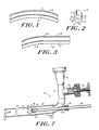
- FIG. 1 A first embodiment of a reconstituted banana confection according to the invention is shown in Figs. 1 and 2.
- the banana confection 10 is arcuate and has, at spaced points about the periphery of the banana confection, a number of grooves simulating the naturally occurring grooves which are characteristic of the surface of peeled bananas, five of which 11, 12, 13, 14 and 15 are shown.
- Fig. 2 it will be noted that there are four radial lines 16, 17, 18 and 19 near the central axis of banana confection 10. These lines are made of the same ingredients as the main body of the confection with caramel colour added. These dark lines, which are about 3/16 inch long, simulate the appearance of banana seeds.
- the banana confection is formed from a partially frozen semi-solid mix comprised primarily of a banana puree prepared from fully riped bananas with the remainder formed of a standard ice cream mix including milkfat and nonfat milk, sugar, corn sweetener, lecithin, stabilizers, such as xanthan, locust bean and guar gums with the addition of vanilla flavouring.
- a banana puree prepared from fully riped bananas with the remainder formed of a standard ice cream mix including milkfat and nonfat milk, sugar, corn sweetener, lecithin, stabilizers, such as xanthan, locust bean and guar gums with the addition of vanilla flavouring.
- FIG. 3 Another embodiment of the reconstituted banana confection is shown in Fig. 3.
- the banana confection 20 has an initial arcuate portion 24 and a straight portion 26, thus simulating the shape of many naturally occurring bananas.
- banana confection 20 has grooves 22 which simulate the grooves on the surface of a peeled banana.
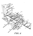
- FIG. 4 The apparatus for making the banana confections of Figs. 1 and 3 is shown in Figs. 4 to 9.
- a horizonal extruder 30 is mounted on a work table 32 upon which mounting base plates 34 and 35 are surmounted.
- Roller guide support blocks 36, 37, 38 and 39 are mounted on base plate 35.
- a roller guide 40 extends between and is supported by blocks 36 and 38 on one side of the device, while on the other side (see Fig. 4) roller guide 41 is parallel to roller guide 40 and is supported by blocks 37 and 39.
- a sleeve 42 surrounds roller guide 40 and extends between roller bearing housings 43 and 44, the roller bearings of which engage roller guide 40.
- a similar sleeve and roller bearing housings relate in the same way to roller guide 41.
- Platform support members 45 and 46 which support a tracking platform 48, are mounted on roller bearing housings 43 and 44, respectively, and similar platform support members ride on the roller bearing housings guided on roller guide 41. As will be explained hereinafter, tracking platform 48 will be driven back and forth on roller guides 40 and 41 by a cam 132.
- a second movable platform 50 is supported above tracking platform 48 on transverse guide rods 52 and 53 which are supported by transverse guide supports 57, only one of which is shown in Fig. 4, mounted on tracking platform 48.
- This transverse platform 50 is slidable along transverse guide rods 52 and 53 by employing low friction bushings 58 and 59.
- a double-acting air cylinder 60 is provided in order to impart transverse movement to transverse platform 50.
- air cylinder 60 is mounted on tracking platform 48 and drives an actuator arm 64 engaged with transverse platform 50.
- a horizontal nozzle head assembly 70 is mounted on transverse platform 50. As shown in Fig. 5, a nozzle barrel 81 of assembly 70 is supported on pillars 66 and 67 extending upwardly from platform 50.
- horizontal extrusion head assembly 70 receives partially frozen semi-solid extrudate through flexible tube 72.
- the extrudate which is cooled to about 20 to 22°F in a freezer is pumped by a variable rate pump (not shown).
- Flexible tube 72 is coupled to a receiving section 74 leading to a valve section 76, which may be partially blocked by a valve member 78 actuated by a valve wheel 79 to provide fine control of the flow rate of the extrudate.
- Course control of the flow rate is provided by the variable rate pump pumping the extrudate from the freezer.
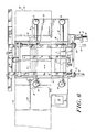
- Valve section 76 leads to an elbow section 80 feeding nozzle barrel 81.
- nozzle barrel 81 Within nozzle barrel 81 is an extrusion chamber 82 which typically may have an internal diameter of 1 1/8 inch and a length of about seven inches.
- the open end 84 of barrel 81 forms a nozzle orifice.
- a number of protuberances 86 are provided at spaced points around the periphery of orifice 84 and extend into the orifice.
- an auxiliary nozzle tube 88 is provided within and concentric to main nozzle barrel 81.
- Nozzle tube 88 enters nozzle barrel 81 through a sleeve 90, which is mounted in a hole in, and is welded to, the wall of elbow 80.
- Nozzle tube 88 is slidably received through sleeve 90 and extends into nozzle barrel 81, being concentric therewith. The position of nozzle tube 88 within nozzle barrel 81 is adjusted and nozzle tube 88 is locked in place by a Cajun Ultra-Torr fitting 92 threaded on a threaded portion of the outer wall of nozzle tube 88.
- a nozzle outlet fitting 93 is connected to the end of nozzle tube 88, and the distal end of nozzle fitting 93 is closed by a closure plate 94.
- a closure plate 94 Located adjacent closure plate 94, four equally spaced slots 96 are cut through the wall of fitting 93.
- baffle members 97 are positioned on the outer wall of fitting 93.
- Each baffle member includes a baffle finger 98 extending outwardly at an angle of about thirty degrees and a base portion 99 welded to the outer surface of fitting 93.
- Nozzle tube 88 has an internal diameter of about 5/16 inch. Slots 96 are about 5/16 inch long and 1/16 inch wide. Fingers 98 are 1/4 inch long and about 1/16 inch wide, while base portion 99 is about 3/8 inch long.
- the flow rate is controlled by controlling the pump rate of a variable rate pump.
- a valve may be provided to control the flow.
- Baffle fingers 98 deflect the flow of the extrudate flowing through extrusion chamber 82 from slots 96 to allow entry into the extrudate stream of the caramel coloured extrudate being extruded through slots 96.
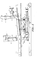
- a cutoff mechanism 100 is provided.
- a standard 102 mounted on base plate 35, supports the cutter mechanism which includes an inverted U-shaped holder 104, the open side of which is closed by a hot cutter wire 106.
- a double acting air cylinder 108 actuates cutter 100, driving hot wire 106 rapidly downwardly through extrudate stream 200 close to nozzle orifice 84 to separate the extrudate stream into individual confection products 10. Air cylinder 108 then immediately retracts hot wire 106.
- Extrudate stream 200 is deposited on a moving conveyor 110 which comprises a plurality of successive product plates 112 mounted for movement with a drive chain 114. As is best seen in Figs.
- Tracking platform 48 is driven in its forward and reverse tracking movements by, as seen in Fig. 8, cam 132 mounted on a cam shaft 130.
- Cam 132 is shaped in a manner well known in the prior art horizontal extruder apparatus as manufactured by Glacier Industries, Inc. of Austin, Texas (for example, see the horizontal extruder used in Glacier Industries, Inc., model "Glacier 600") to impart tracking movement to tracking platform 48 first in the same direction as the moving product plates 112 of conveyor 110, but at a slower speed, and then after cutter 100 has sliced extrudate stream 200, to drive tracking platform 48 rapidly back to its starting position in time to deposit the extrudate stream on the next product plate.
- the motion of cam 132 is imparted from the cam by cam follower 134 through a connecting rod 136, the other end of which is mounted on tracking table 48, as seen in Fig. 5.
- the drive mechanism for the apparatus includes a drive motor 116 driving a drive shaft 118.
- a sprocket 120 on drive shaft 118 drives a chain 121 engaged with a sprocket 122 on conveyor drive shaft 123.
- a drive sprocket 124 on shaft 123 is engaged with conveyor chain 114 driving the chain and with it, product plates 112, continuously.
- Another sprocket 125 on motor shaft 118 drives a chain 126 which, in turn, drives sprocket 128 on cam shaft 130, thus driving cam 132.
- a sprocket 138 on cam shaft 130 drives a chain 140 which is engaged with a sprocket 142 on candy switch shaft 144.
- a pair of candy switches 146 and 148 are mounted in tandem on switch shaft 144. Each of the candy switches is adjusted to close switches at selected times during the cycle of rotation of switch shaft 144. Since switch shaft 144 is driven from the same drive motor 116 as conveyor drive shaft 123, it will be readily appreciated that the rotation of switch shaft 144 is directly related to the rotation of conveyor drive shaft 123 and, hence, to the positions of product plates 112 relative to nozzle orifice 84 of horizontal nozzle head assembly 70. Thus, the times of the closure of switches in candy switches 146 and 148 can be related to the positions of successive product plates 112 as they pass under extruder head assembly 70.
- Candy switch 146 controls switches in an air cylinder control circuit 150 for controlling air cylinder 60 which imparts transverse movement to extruder head assembly 70. Likewise, the switches controlled in candy switch 148 are part of air cylinder control circuit 152 for controlling air cylinder 108 which actuates cutter 100.
- air cylinder control circuit 150 controls the application of compressed air to and the exhaust of air from either side of double-acting air cylinder 60.
- the cylinder has a piston 160, on which actuator arm 64 is mounted, a chamber 162 above the piston and a chamber 164 below the piston (referring to the orientation of the cylinder in the figure).
- a source of compressed air 166 from an air compressor is connected through conduits 168 and 169 to respective solenoid valves 170 and 176.
- Actuation of solenoid valve 170 is controlled by a switch 171, which is closed in candy switch 146, connecting the solenoid in circuit with power supply 191 through line 172.
- the candy switch closes a switch 189 completing the circuit through the solenoid of a solenoid valve 188 from power supply line 190 to actuate valve 188 opening an exhaust line 186.
- valve 170 compressed air is supplied to chamber 162 driving piston 160 down as air is exhausted through valve 188.
- the rate of movement of piston 160 is a function of the rate at which air is exhausted through exhaust line 186, valve 188, exhaust line 192, and a manually adjustable flow control valve 196.
- valve 188 itself may incorporate the adjustment function, and flow control valve 196 could be omitted.
- flow control valve 196 is adjusted to restrict the exhaustion of air from chamber 164 so that movement of piston 160 will continue until one half the length of the extruded product has been deposited on a product plate 112.
- candy switch 146 closes switches 177 and 183, completing the circuits to solenoid valves 176 and 182 from voltage source lines 178 and 184 respectively.
- Compressed air is now directed through valve 176 through conduit 179 to chamber 164, and air is exhausted from chamber 162 through conduit 180, valve 182, conduit 185 and flow control valve 194.
- switches 177 and 183 are closed at the product halfway point to initiate the return transverse movement; flow control valve 194 restricts air exhaustion from chamber 162 so that the return movement of piston 160 is completed at the time cutter 100 is actuated.
- the outward transverse movement is again completed at the product halfway point, but switches 177 and 183 are not closed until just after actuation of cutter 100.
- compressed air is applied to chamber 164 through valve 176, and exhausted from chamber 162 through valves 182 and 194.
- valve 194 does not restrict flow as much with the result that the return transverse movement is rapid and completed before it is again time to initiate outward transverse movement.
- Control circuit 152 for air cylinder 108 of cutoff device 100 is virtually identical to control circuit 150 just described. However, because cutter 100 is operated rapidly in both its slicing and retraction movements, there is no need for flow control on the exhaust side. Of course, the timing of the closure of switches in control circuit 152 will be determined in candy switch 148.
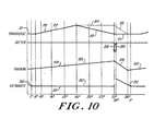
- curve 201 represents the relationship of extrudate stream 200 and a product plate 112.
- Curve 204 represents the tracking motion of tracking platform 48 in the same direction or the reverse direction as product plates 112 and extrudate stream 200.
- Arrows 208 and 209 indicate respectively, the cutting motion of hot wire cutter 106 and the retraction thereof.
- Curve 210 represents the transverse movement of transverse platform 50 in a direction perpendicular to the direction of motion of tracking platform 48, product plates 112 and extrudate stream 200.
- the horizontal co-ordinates of the diagram of Fig. 10 represent the rotation of cam 132 in radians.
- both tracking platform 48 and transverse platform 50 are at their starting positions as indicated by the positions of curve 204 and 210.
- Extrudate stream 200 is not yet in contact with a product plate 112. This is indicated by the raised position of curve section 202.
- the forward tracking movement of tracking platform 48 is initiated by cam 132 and, as shown by curve section 205, movement in the forward tracking direction begins.
- transverse platform 50 remains in its starting position.
- extrudate stream 200 begins to be deposited on a product plate 112; and curve section 203 signifies that the extrudate stream is thereafter laid on a product plate 112.
- transverse platform 50 Shortly thereafter at 10°, outward transverse movement of transverse platform 50 begins, as indicated by curve section 212, and continues until about half the product is deposited on product plate 112 at about 180°.
- the transverse movement of transverse table 50 reverses direction, as controlled by air cylinder 60, and begins its transverse movement back to its starting position as shown by curve section 213.
- transverse platform 50 is back to its starting position and cutter 100 initiates movement of hot wire 106 through extrudate stream 200 as indicated by arrow 208.
- the cutter wire 106 is retracted as shown by arrow 209.
- transverse movement of transverse platform 50 begins, as before at time 10°, and outward movement 212 continues until time 180°. At this time, the outward position is held constant, as shown by dash line curve portion 214, until 315°. Transverse platform 50 then is returned rapidly transversely to its initial position, as shown by dash line curve portion 215, arriving there by 360°.
- the resulting product as illustrated by product 20 of Fig. 3, has an arcuate portion 24 and a straight portion 26, simulating the hook-like configuration of some bananas.
- transverse platform 50 Although two embodiments involving two different modes of transverse motion of transverse platform 50 have been disclosed, it will be readily appreciated that other patterns of transverse movement of transverse platform 50 may be used. It is therefore possible, by appropriate adjustment of the timing of the outward and return movements, to extrude banana-shaped products of slightly different shapes and proportions as well as a wide variety of other extruded confections having, at least in part, arcuate configurations.
- extrudate stream 200 is sliced by cutter 100, the now separate products 10 or 20 are moved by product plates 112 of conveyor 110 into a hardening tunnel where they are hard frozen.
- the extrudate In order to retain the groove indentations made by protuberances 86 until product 10 or 20 reaches the hardening tunnel, it is necessary that the extrudate be of sufficient stiffness. This can be adjusted by appropriate choices of the temperature and thickness of the extrudate mixture.
- the stiffness of the extrudate also affects the extent of the arc imparted by the transverse movement. Stiffer extrudates tend to resist the arcuate deflection of the product with the resulting products having arc deflections somewhat smaller than the transverse movement of platform 50, while the arcs of looser extrudates more closely follow the amplitude of the transverse movement of platform 50.
- the size of the lateral displacement of transverse platform 50 is thus determined by the desired arcuate deflection in the product with due allowance for the aforementioned stiffness factor. It has been found, for example, that a transverse displacement of transverse platform 50 of 1 to 1 1/2 inches will provide a satisfactory arcuate displacement of about 1/2 inch in the resulting product.
- the rate of flow of extrudate from extrusion head assembly 70 must be related to the speed of product plates 112 of conveyor 110, the speed of which is variable up to sixty plates per minute.
- a number of laterally spaced horizontal extrusion head assemblies 70 may operate in parallel in a common extrusion head manifold supplied with extrudate from common supply lines for the main extrudate and the caramel coloured extrudate supplied to auxilliary nozzle tube 88.
- Several extrudate streams 200 may be sliced by a single cutter 100 and a like number of products may be laid down on a common product plate 112. All of the extrusion head assemblies 70, in this case, would be mounted on common tracking and transverse platforms 48 and 50 which will operate as described above.
- the described apparatus and method produces frozen confections of arcuate configuration economically.
- the banana-like products are of uniform quality, are tasty and closely resemble in taste and texture, as well as appearance, natural bananas which have been frozen and coated with chocolate or other confection coating.
Abstract
Description
- This invention relates to an apparatus and method for extruding arcuate products e.g. frozen confections and, more particularly, to an apparatus and method for extruding reconstituted banana confections having a banana-like configuration and to reconstituted banana confections as made by the apparatus and method of the invention.
- Frozen bananas dipped or otherwise coated with chocolate or other candy-like coatings, often with an additional layer of crushed nuts, have become popular confections. However, such frozen banana confections frequently are not of uniform quality due to a lack of uniform ripeness in the bananas used and due to the tendency of the bananas to turn black and thus be perceived by the customer as unpalatable. Moreover, coated frozen banana confections are not amenable to automated processing.
- It has been suggested in the prior art that simulated fruit confections may be made by extruding fruit purees mixed with additional ingredients. See, for example, U.S. Patent No. 4,117,172 and U.S. Patent No. 4,119,739 which teach making simulated berries and cherries in this way. However, the arcuate configuration of bananas cannot be readily replicated with existing extrusion apparatus. Although U.S. Patent No. 4,152,102 and U.S. Patent No. 4,025,260 teach the use of shaped extrusion nozzles for forming semi-circular or curled food products, it is difficult with such shaped nozzles to effect the arcuate shape and generally round cross section of bananas. It is also difficult with such apparatus to provide colouring material within the reconsituted banana to simulate the banana's seeds.
- More promising are horizontal extruders of the type manufactured by Glacier Industries Inc. which can extrude elongated frozen confection "logs" and which are amenable to the use of auxiliary extrusion orifices within the extrusion chamber to effect variations in the colour of the product cross section as is shown, for example, in U.S. Patent No. 3,840,311. Such machines include an extrusion head assembly mounted on a movable tracking platform and having a horizontal extrusion nozzle. The extrusion nozzle is positioned above moving product plates of a conveyor and extrudes a semi-solid extrudate stream. The platform is moved so that the extrusion nozzle tracks the moving product plates moving from a starting point in the same direction as the plates, but at a slower speed, as the extrusion stream is deposited on a product plate. After a confection product of desired length is deposited on the product plate, a hot wire cutoff device slices the extrudate stream. The platform is then moved rapidly in the reverse direction to bring the extrusion nozzle back to the starting point in time to deposit the next confection product on the next moving product plate. While the extrusion nozzle orifice may be shaped and dimensioned so that the confection products have the generally round cross section and diameter of bananas, the confections will be straight, unlike the arcuate configuration of bananas.
- An object of the present invention is to provide a reconstituted banana confection.
- A further object of the present invention is to provide extruder apparatus for arcuate products e.g. confection products thus enabling confection products having banana-like configurations to be produced.
- Other objects concern the provision of means to simulate the seeds of a banana in the reconstituted banana confection of the invention and the provision of longitudinal grooves on the surface of the product to simulate the grooves on the surface of a peeled banana.
- Briefly, according to the present invention, the aforementioned prior art horizontal extruder equipment is modified by providing drive means to displace the extrusion head assembly, and with it the extrusion nozzle, transversely of the direction of motion of the extrudate stream and of the product plates of the conveyor, one such cycle of trasnverse motion being effected for each successive product as it is deposited on a product plate. As a result, each of the products is arcuate. The transverse movement begins after the extrudate stream first touches the product plate during the forward tracking movement of the extrusion head assembly. In one embodiment, the outward transverse movement is continuous with the return transverse movement so that the product is formed with a continuous arc. In a second embodiment, the outward transverse movement is completed about halfway through the deposit of a product with the transverse displacement then held until the hot wire cutoff device has sliced the extrudate stream at which time the extrusion head assembly is rapidly returned to its initial transverse position. The resulting product has an initial arcuate portion and a final straight portion - a shape characteristic of bananas.
- The reconstituted bananas are formed of a partially frozen extrudate comprising primarily of fully ripened banana puree with the addition of standard ice cream ingredients, including milkfat and nonfat milk, sweeteners, lecithin and stabilizers. After the product is enrobed with chocolate and crushed peanuts, it to a large extent duplicates the flavour, texture and appearance of a chocolate coated frozen banana confection.
- In order to simulate the appearance of banana seeds, the extrusion head comprises within a main outer nozzle an inner nozzle having a plurality of radial apertures for a caramel coloured extrudate which effect the appearance of banana seeds in the simulated banana products. The inner nozzle is formed by a tube having a closed end and a plurality of slots extending from the end at spaced points around the wall of the tube. The slots are shielded by a like number of fingers extending outwardly at an angle from the base of the slots. By properly controlling the flow rate of the caramel coloured extrudate, the central portion of the extruded product includes a plurality of radial lines of darker colour resembling the seeds of a banana.
- In order to mimic the appearance of the grooves which extend longitudinally on the surface of a peeled banana, a number of spaced protuberances are placed at spaced points about the periphery of the main nozzle orifice.
- Some ways of carrying out the invention will now be described in detail by way of example with reference to drawings which show two specific embodiments of banana confection in accordance with the present invention and one specific embodiment of apparatus according to the present invention.
-
- FIG. 1 is a plan view of a banana confection of the invention;
- FIG. 2 is a perspective view of the banana confection of Fig. 1, viewed from an end;
- FIG. 3 is a plan view of a second embodiment of a banana confection of the invention;
- FIG. 4 is a perspective overall view of an apparatus of the invention;
- FIG. 5 is a side elevation view of apparatus of the invention;
- FIG. 6 is a top view of the apparatus of the invention;
- FIG. 7 is a section view of the extrusion nozzle of the apparatus of the invention;
- FIG. 8 is a schematic diagram of the drive mechanism of the apparatus of the invention;
- FIG. 9 is a circuit diagram showing the control circuit of an air cylinder of the apparatus of the invention; and
- FIG. 10 is a timing diagram for illustrating the operation of the apparatus
- A first embodiment of a reconstituted banana confection according to the invention is shown in Figs. 1 and 2. The
banana confection 10 is arcuate and has, at spaced points about the periphery of the banana confection, a number of grooves simulating the naturally occurring grooves which are characteristic of the surface of peeled bananas, five of which 11, 12, 13, 14 and 15 are shown. In the perspective view of Fig. 2, it will be noted that there are fourradial lines banana confection 10. These lines are made of the same ingredients as the main body of the confection with caramel colour added. These dark lines, which are about 3/16 inch long, simulate the appearance of banana seeds. - The banana confection is formed from a partially frozen semi-solid mix comprised primarily of a banana puree prepared from fully riped bananas with the remainder formed of a standard ice cream mix including milkfat and nonfat milk, sugar, corn sweetener, lecithin, stabilizers, such as xanthan, locust bean and guar gums with the addition of vanilla flavouring. When enrobed with chocolate and crushed peanuts and frozen, the product resembles chocolate covered frozen bananas in appearance (with the ends sliced off), texture and flavour.
- Another embodiment of the reconstituted banana confection is shown in Fig. 3. The
banana confection 20 has an initialarcuate portion 24 and astraight portion 26, thus simulating the shape of many naturally occurring bananas. As with the embodiments of Figs. 1 and 2,banana confection 20 hasgrooves 22 which simulate the grooves on the surface of a peeled banana. - The apparatus for making the banana confections of Figs. 1 and 3 is shown in Figs. 4 to 9. A
horizonal extruder 30 is mounted on a work table 32 upon which mountingbase plates guide support blocks base plate 35. Aroller guide 40 extends between and is supported byblocks roller guide 41 is parallel toroller guide 40 and is supported byblocks sleeve 42 surroundsroller guide 40 and extends betweenroller bearing housings roller guide 40. A similar sleeve and roller bearing housings (not shown) relate in the same way toroller guide 41. - Platform support members 45 and 46, which support a
tracking platform 48, are mounted onroller bearing housings roller guide 41. As will be explained hereinafter, trackingplatform 48 will be driven back and forth on roller guides 40 and 41 by acam 132. - A second
movable platform 50 is supported above trackingplatform 48 ontransverse guide rods platform 48. Thistransverse platform 50 is slidable alongtransverse guide rods low friction bushings transverse platform 50, a double-actingair cylinder 60 is provided. As is seen in Figs. 4 and 6,air cylinder 60 is mounted on trackingplatform 48 and drives anactuator arm 64 engaged withtransverse platform 50. - A horizontal
nozzle head assembly 70 is mounted ontransverse platform 50. As shown in Fig. 5, anozzle barrel 81 ofassembly 70 is supported onpillars platform 50. - As is best seen in Figs. 5 and 7, horizontal
extrusion head assembly 70 receives partially frozen semi-solid extrudate throughflexible tube 72. The extrudate which is cooled to about 20 to 22°F in a freezer is pumped by a variable rate pump (not shown).Flexible tube 72 is coupled to a receivingsection 74 leading to avalve section 76, which may be partially blocked by a valve member 78 actuated by avalve wheel 79 to provide fine control of the flow rate of the extrudate. Course control of the flow rate is provided by the variable rate pump pumping the extrudate from the freezer.Valve section 76 leads to anelbow section 80feeding nozzle barrel 81. Withinnozzle barrel 81 is an extrusion chamber 82 which typically may have an internal diameter of 1 1/8 inch and a length of about seven inches. Theopen end 84 ofbarrel 81 forms a nozzle orifice. In order to provide longitudinal grooves on the surface of the extruded product to simulate the grooves which naturally appear on the surface of a peeled banana, a number ofprotuberances 86 are provided at spaced points around the periphery oforifice 84 and extend into the orifice. - So that the extruded product will contain
darkened marks auxiliary nozzle tube 88 is provided within and concentric tomain nozzle barrel 81.Nozzle tube 88 entersnozzle barrel 81 through asleeve 90, which is mounted in a hole in, and is welded to, the wall ofelbow 80.Nozzle tube 88 is slidably received throughsleeve 90 and extends intonozzle barrel 81, being concentric therewith. The position ofnozzle tube 88 withinnozzle barrel 81 is adjusted andnozzle tube 88 is locked in place by a Cajun Ultra-Torr fitting 92 threaded on a threaded portion of the outer wall ofnozzle tube 88. - A nozzle outlet fitting 93 is connected to the end of
nozzle tube 88, and the distal end of nozzle fitting 93 is closed by aclosure plate 94. Immediatelyadjacent closure plate 94, four equally spacedslots 96 are cut through the wall of fitting 93. Just behind these slots, four baffle members 97 are positioned on the outer wall of fitting 93. Each baffle member includes a baffle finger 98 extending outwardly at an angle of about thirty degrees and abase portion 99 welded to the outer surface of fitting 93.Nozzle tube 88 has an internal diameter of about 5/16 inch.Slots 96 are about 5/16 inch long and 1/16 inch wide. Fingers 98 are 1/4 inch long and about 1/16 inch wide, whilebase portion 99 is about 3/8 inch long. - An extrudate which is identical to the extrudate provided through
tube 72, but with addition of a caramel colouring agent, is pumped intonozzle tube 88 from a freezer. The flow rate is controlled by controlling the pump rate of a variable rate pump. Alternatively, a valve may be provided to control the flow. Baffle fingers 98 deflect the flow of the extrudate flowing through extrusion chamber 82 fromslots 96 to allow entry into the extrudate stream of the caramel coloured extrudate being extruded throughslots 96. - In order to slice the
extrudate stream 200 flowing horizontally fromnozzle head assembly 70, acutoff mechanism 100 is provided. A standard 102, mounted onbase plate 35, supports the cutter mechanism which includes an invertedU-shaped holder 104, the open side of which is closed by ahot cutter wire 106. A doubleacting air cylinder 108 actuatescutter 100, drivinghot wire 106 rapidly downwardly throughextrudate stream 200 close tonozzle orifice 84 to separate the extrudate stream intoindividual confection products 10.Air cylinder 108 then immediately retractshot wire 106.Extrudate stream 200 is deposited on a movingconveyor 110 which comprises a plurality ofsuccessive product plates 112 mounted for movement with adrive chain 114. As is best seen in Figs. 4 and 5,product plates 112 are moved through a gap provided abovetransverse platform 50 and below horizontalextrusion head assembly 70.Extrudate stream 200, moving horizontally fromextrusion head assembly 70, is thus deposited from above upon successive product plates moving in the same direction. -
Tracking platform 48 is driven in its forward and reverse tracking movements by, as seen in Fig. 8,cam 132 mounted on acam shaft 130.Cam 132 is shaped in a manner well known in the prior art horizontal extruder apparatus as manufactured by Glacier Industries, Inc. of Austin, Texas (for example, see the horizontal extruder used in Glacier Industries, Inc., model "Glacier 600") to impart tracking movement to trackingplatform 48 first in the same direction as the movingproduct plates 112 ofconveyor 110, but at a slower speed, and then aftercutter 100 has slicedextrudate stream 200, to drive trackingplatform 48 rapidly back to its starting position in time to deposit the extrudate stream on the next product plate. The motion ofcam 132 is imparted from the cam bycam follower 134 through a connectingrod 136, the other end of which is mounted on tracking table 48, as seen in Fig. 5. - As shown in Fig. 8, the drive mechanism for the apparatus includes a
drive motor 116 driving adrive shaft 118. Asprocket 120 ondrive shaft 118 drives achain 121 engaged with asprocket 122 onconveyor drive shaft 123. A drive sprocket 124 onshaft 123 is engaged withconveyor chain 114 driving the chain and with it,product plates 112, continuously. Anothersprocket 125 onmotor shaft 118 drives achain 126 which, in turn, drivessprocket 128 oncam shaft 130, thus drivingcam 132. Asprocket 138 oncam shaft 130 drives a chain 140 which is engaged with asprocket 142 oncandy switch shaft 144. A pair ofcandy switches switch shaft 144. Each of the candy switches is adjusted to close switches at selected times during the cycle of rotation ofswitch shaft 144. Sinceswitch shaft 144 is driven from thesame drive motor 116 asconveyor drive shaft 123, it will be readily appreciated that the rotation ofswitch shaft 144 is directly related to the rotation ofconveyor drive shaft 123 and, hence, to the positions ofproduct plates 112 relative tonozzle orifice 84 of horizontalnozzle head assembly 70. Thus, the times of the closure of switches incandy switches successive product plates 112 as they pass underextruder head assembly 70.Candy switch 146 controls switches in an aircylinder control circuit 150 for controllingair cylinder 60 which imparts transverse movement to extruderhead assembly 70. Likewise, the switches controlled incandy switch 148 are part of aircylinder control circuit 152 for controllingair cylinder 108 which actuatescutter 100. - Turning to Fig. 9, air
cylinder control circuit 150 controls the application of compressed air to and the exhaust of air from either side of double-actingair cylinder 60. The cylinder has apiston 160, on whichactuator arm 64 is mounted, achamber 162 above the piston and achamber 164 below the piston (referring to the orientation of the cylinder in the figure). A source ofcompressed air 166 from an air compressor is connected throughconduits switch 171, which is closed incandy switch 146, connecting the solenoid in circuit withpower supply 191 throughline 172. At the same time, the candy switch closes aswitch 189 completing the circuit through the solenoid of asolenoid valve 188 frompower supply line 190 to actuatevalve 188 opening anexhaust line 186. Upon the actuation of valve 170, compressed air is supplied tochamber 162driving piston 160 down as air is exhausted throughvalve 188. The rate of movement ofpiston 160 is a function of the rate at which air is exhausted throughexhaust line 186,valve 188, exhaust line 192, and a manually adjustableflow control valve 196. In practice,valve 188 itself may incorporate the adjustment function, and flowcontrol valve 196 could be omitted. Since the transverse movement oftransverse platform 50 in the outward direction corresponds with about one half the length of the extruded product,flow control valve 196 is adjusted to restrict the exhaustion of air fromchamber 164 so that movement ofpiston 160 will continue until one half the length of the extruded product has been deposited on aproduct plate 112. When it is time to retract transverse table 50,candy switch 146 closesswitches 177 and 183, completing the circuits to solenoidvalves 176 and 182 fromvoltage source lines 178 and 184 respectively. Compressed air is now directed through valve 176 throughconduit 179 tochamber 164, and air is exhausted fromchamber 162 through conduit 180,valve 182, conduit 185 and flowcontrol valve 194. In one embodiment, switches 177 and 183 are closed at the product halfway point to initiate the return transverse movement; flowcontrol valve 194 restricts air exhaustion fromchamber 162 so that the return movement ofpiston 160 is completed at thetime cutter 100 is actuated. - In a second embodiment, the outward transverse movement is again completed at the product halfway point, but switches 177 and 183 are not closed until just after actuation of
cutter 100. At this time, compressed air is applied tochamber 164 through valve 176, and exhausted fromchamber 162 throughvalves valve 194 does not restrict flow as much with the result that the return transverse movement is rapid and completed before it is again time to initiate outward transverse movement. -
Control circuit 152 forair cylinder 108 ofcutoff device 100 is virtually identical to controlcircuit 150 just described. However, becausecutter 100 is operated rapidly in both its slicing and retraction movements, there is no need for flow control on the exhaust side. Of course, the timing of the closure of switches incontrol circuit 152 will be determined incandy switch 148. - The operation of the apparatus will now be described with reference to the timing diagram of Fig. 10 in which curve 201 represents the relationship of
extrudate stream 200 and aproduct plate 112. Curve 204 represents the tracking motion of trackingplatform 48 in the same direction or the reverse direction asproduct plates 112 andextrudate stream 200. Arrows 208 and 209 indicate respectively, the cutting motion ofhot wire cutter 106 and the retraction thereof.Curve 210 represents the transverse movement oftransverse platform 50 in a direction perpendicular to the direction of motion of trackingplatform 48,product plates 112 andextrudate stream 200. The horizontal co-ordinates of the diagram of Fig. 10 represent the rotation ofcam 132 in radians. At 0°, both trackingplatform 48 andtransverse platform 50 are at their starting positions as indicated by the positions ofcurve 204 and 210.Extrudate stream 200, however, as shown bycurve 201, having recently been sliced bycutter 100, is not yet in contact with aproduct plate 112. This is indicated by the raised position ofcurve section 202. Beginning at 0°, the forward tracking movement of trackingplatform 48 is initiated bycam 132 and, as shown bycurve section 205, movement in the forward tracking direction begins. However, as shown bycurve section 211,transverse platform 50 remains in its starting position. At 5°,extrudate stream 200, as indicated bycurve 201, begins to be deposited on aproduct plate 112; andcurve section 203 signifies that the extrudate stream is thereafter laid on aproduct plate 112. Shortly thereafter at 10°, outward transverse movement oftransverse platform 50 begins, as indicated bycurve section 212, and continues until about half the product is deposited onproduct plate 112 at about 180°. In the case of the first embodiment, at 180° the transverse movement of transverse table 50 reverses direction, as controlled byair cylinder 60, and begins its transverse movement back to its starting position as shown bycurve section 213. At 315°,transverse platform 50 is back to its starting position andcutter 100 initiates movement ofhot wire 106 throughextrudate stream 200 as indicated by arrow 208. Immediately thereafter, at 316°, thecutter wire 106 is retracted as shown by arrow 209. At 315° also, forward tracking motion of trackingplatform 48 is completed, andcam 132 reverses the direction of trackingplatform 48 as indicated bycurve section 206. The reverse or flyback tracking motion is rapid and is completed by 360°, the start of the next product cycle, allowing time forextrudate stream 200 to come into contact with thenext product plate 112 at 5°, as indicated bycurve section 202. By virtue of the transverse movement oftransverse platform 50, the resulting product has the continuously arcuate banana-like configuration illustrated byproduct 10 in Fig. 1. - In the second embodiment, a different mode of operation is used. The transverse movement of
transverse platform 50 begins, as before attime 10°, andoutward movement 212 continues until time 180°. At this time, the outward position is held constant, as shown by dash line curve portion 214, until 315°.Transverse platform 50 then is returned rapidly transversely to its initial position, as shown by dashline curve portion 215, arriving there by 360°. The resulting product, as illustrated byproduct 20 of Fig. 3, has anarcuate portion 24 and astraight portion 26, simulating the hook-like configuration of some bananas. - Although two embodiments involving two different modes of transverse motion of
transverse platform 50 have been disclosed, it will be readily appreciated that other patterns of transverse movement oftransverse platform 50 may be used. It is therefore possible, by appropriate adjustment of the timing of the outward and return movements, to extrude banana-shaped products of slightly different shapes and proportions as well as a wide variety of other extruded confections having, at least in part, arcuate configurations. - After
extrudate stream 200 is sliced bycutter 100, the nowseparate products product plates 112 ofconveyor 110 into a hardening tunnel where they are hard frozen. In order to retain the groove indentations made byprotuberances 86 untilproduct - The stiffness of the extrudate also affects the extent of the arc imparted by the transverse movement. Stiffer extrudates tend to resist the arcuate deflection of the product with the resulting products having arc deflections somewhat smaller than the transverse movement of
platform 50, while the arcs of looser extrudates more closely follow the amplitude of the transverse movement ofplatform 50. The size of the lateral displacement oftransverse platform 50 is thus determined by the desired arcuate deflection in the product with due allowance for the aforementioned stiffness factor. It has been found, for example, that a transverse displacement oftransverse platform 50 of 1 to 1 1/2 inches will provide a satisfactory arcuate displacement of about 1/2 inch in the resulting product. - After the products are hard frozen, they are removed from
product plates 112 into an enrobing unit where they are enrobed with chocolate or other coating and then transferred to wrapping apparatus. - As is known in the horizontal extruder art, the rate of flow of extrudate from
extrusion head assembly 70 must be related to the speed ofproduct plates 112 ofconveyor 110, the speed of which is variable up to sixty plates per minute. The speed Vt of the tracking movement of trackingplatform 48 is related to the speed Vp ofproduct plates 112 and the speed of the extrudate stream Ve in accordance with the equation Vt = Vp - Ve. - The length Lt of the forward tracking movement of tracking
platform 48 is governed by the following equation in which Lp is the length of theproduct plates 112, Le is the length of the extruded product, and R is the flyback time in degrees:
Lt = Lp - Le -
Thus, in the case of 7 1/2inch product plates 112, a product length of 5 1/2 inches, and a flyback of trackingplatform 48 of 45°, the forward tracking distance is 1 3/4 inches. - In commercial production of the confections of the invention, a number of laterally spaced horizontal
extrusion head assemblies 70 may operate in parallel in a common extrusion head manifold supplied with extrudate from common supply lines for the main extrudate and the caramel coloured extrudate supplied toauxilliary nozzle tube 88. Several extrudate streams 200 may be sliced by asingle cutter 100 and a like number of products may be laid down on acommon product plate 112. All of theextrusion head assemblies 70, in this case, would be mounted on common tracking andtransverse platforms - The described apparatus and method produces frozen confections of arcuate configuration economically. The banana-like products are of uniform quality, are tasty and closely resemble in taste and texture, as well as appearance, natural bananas which have been frozen and coated with chocolate or other confection coating.
- Although an
air cylinder 60 has been used in the disclosed embodiments, it will be appreciated that equivalent drive means, such as cam means, can instead be used to impart the transverse movement totransverse platform 50.
Claims (14)
extruding a semi-solid extrudate comprising primarily banana puree and ice cream through an extrusion nozzle having an extrusion aperture of substantially round configuration to form an extrudate stream which is deposited upon conveyor means moving in the same direction as said extrudate stream;
displacing said extrusion nozzle transversely of said direction as said extrudate stream is extruded and deposited on said conveyor means, whereby each of said products is arcuate; and
severing said extrudate stream into individual banana confection products deposited on said conveyor means.
an extrusion nozzle including an elongated extrusion chamber for extruding a main extrudate stream through a nozzle orifice at one end of said chamber;
an auxilliary nozzle tube located within and centrally of said extrusion chamber for extruding an extrudate of contrasting colour and having a closed end and a plurality of slots adjacent said closed end; and
baffle means mounted on said auxiliary nozzle tube to deflect said main extrudate stream from said slots, whereby said extrudate of contrasting colour is incorporated as a pattern within said main extrudate.
Applications Claiming Priority (2)
| Application Number | Priority Date | Filing Date | Title |
|---|---|---|---|
| US928152 | 1986-11-07 | ||
| US06/928,152 US4793786A (en) | 1986-11-07 | 1986-11-07 | Extrusion of arcuate products |
Publications (2)
| Publication Number | Publication Date |
|---|---|
| EP0277408A2 true EP0277408A2 (en) | 1988-08-10 |
| EP0277408A3 EP0277408A3 (en) | 1988-12-07 |
Family
ID=25455807
Family Applications (1)
| Application Number | Title | Priority Date | Filing Date |
|---|---|---|---|
| EP87305870A Withdrawn EP0277408A3 (en) | 1986-11-07 | 1987-07-02 | Extrusion of curved products |
Country Status (5)
| Country | Link |
|---|---|
| US (1) | US4793786A (en) |
| EP (1) | EP0277408A3 (en) |
| JP (1) | JPS63133945A (en) |
| AU (1) | AU7680587A (en) |
| DK (1) | DK350587A (en) |
Cited By (5)
| Publication number | Priority date | Publication date | Assignee | Title |
|---|---|---|---|---|
| EP0600107A1 (en) * | 1992-11-28 | 1994-06-08 | Frisco-Findus Ag | Process and device for manufacturing frozen cake with crunchy layers |
| EP1057413A1 (en) * | 1999-05-27 | 2000-12-06 | Société des Produits Nestlé S.A. | Extrusion process for laminated candy products |
| WO2000078159A1 (en) * | 1999-06-18 | 2000-12-28 | Gram A/S | Shaping confectionery products by horizontal extrusion |
| US6689406B2 (en) | 2000-12-05 | 2004-02-10 | Nestec S.A. | Chocolate coating process and device for same |
| WO2012080282A1 (en) * | 2010-12-16 | 2012-06-21 | Unilever Plc | Process for preparing frozen confectionery products |
Families Citing this family (12)
| Publication number | Priority date | Publication date | Assignee | Title |
|---|---|---|---|---|
| US5562875A (en) * | 1988-06-17 | 1996-10-08 | Gencorp Inc. | Handling system and method for curved extrusions |
| US5067885A (en) * | 1988-06-17 | 1991-11-26 | Gencorp Inc. | Rapid change die assembly |
| US5219588A (en) * | 1990-02-12 | 1993-06-15 | Gencorp Inc. | Die assembly control |
| US5209156A (en) * | 1991-10-31 | 1993-05-11 | Lombard Marco H | Extruding and cutting frozen confections containing edible particulates |
| JP3310134B2 (en) * | 1995-05-24 | 2002-07-29 | オークマ株式会社 | Machine Tools |
| US7134861B2 (en) * | 2000-02-01 | 2006-11-14 | Barber Foods | Extrusion nozzle |
| US6511309B1 (en) | 2000-05-24 | 2003-01-28 | Kerry, Inc. | Extruder die and cutter assembly for extruding filled food pieces |
| US6592928B2 (en) | 2000-11-15 | 2003-07-15 | Nestec S.A. | Festooned laminated candy and methods for making same |
| US6616963B1 (en) | 2000-11-15 | 2003-09-09 | Nestec S.A. | Laminated candy products made by an extrusion process |
| US6805890B2 (en) * | 2001-09-06 | 2004-10-19 | Nestec S.A. | Laminated, extruded candy products |
| US6964562B2 (en) * | 2002-06-11 | 2005-11-15 | Kerry, Inc. | Extruder die and cutter assembly for extruding filled food pieces |
| WO2009129376A2 (en) * | 2008-04-16 | 2009-10-22 | Kerry, Inc. | Co-extruder having a filling entrance from the rear |
Citations (17)
| Publication number | Priority date | Publication date | Assignee | Title |
|---|---|---|---|---|
| US1493082A (en) * | 1920-10-19 | 1924-05-06 | William B Laskey | Machine for forming and striping stick candy |
| GB368890A (en) * | 1931-01-01 | 1932-03-17 | Sydney Malcolm White | A new form of sweetmeat |
| GB370006A (en) * | 1931-01-01 | 1932-04-01 | Sydney Malcolm White | A new form of sweetmeat |
| US2054835A (en) * | 1933-10-12 | 1936-09-22 | Vogt Processes Inc | Ice cream manufacture |
| FR810911A (en) * | 1936-08-26 | 1937-04-02 | Vogt Processes | Apparatus for the continuous manufacture of ice-cream articles |
| US2284651A (en) * | 1940-04-10 | 1942-06-02 | Joe Lowe Corp | Method of and apparatus for making a variegated ice cream or similar substance |
| US2389084A (en) * | 1943-09-08 | 1945-11-13 | Almond C Routh | Apparatus for making flavored confections |
| FR1025184A (en) * | 1949-09-27 | 1953-04-13 | Toms Lab As | Machine for the extrusion of chocolate or similar plastics |
| GB702565A (en) * | 1951-08-24 | 1954-01-20 | Lyons & Co Ltd J | Improvements relating to sweetmeats |
| GB712402A (en) * | 1951-04-24 | 1954-07-21 | S B Engineering Company Ltd | Improvements in or relating to the manufacture of plastic material such as ice cream |
| GB835236A (en) * | 1955-10-13 | 1960-05-18 | Gerald George Balch | Method and apparatus for incorporating two or more different or differently coloured flowable plastic substances into one mass to produce a variegated effect in the mass |
| US3280763A (en) * | 1964-04-13 | 1966-10-25 | Komberec And Fiedler Entpr Inc | Iced confection extrusion apparatus |
| FR2022412A1 (en) * | 1968-11-01 | 1970-07-31 | Unilever Nv | |
| FR2114706A5 (en) * | 1970-11-16 | 1972-06-30 | Unilever Nv | |
| FR2309156A1 (en) * | 1975-04-30 | 1976-11-26 | Guntzer Armand | Prepn. of strips of pasty materials - such as chewing gum by extrusion onto moving belt |
| FR2505614A1 (en) * | 1981-05-15 | 1982-11-19 | Towae Gerard | Extrusion dies for producing alternative striped extrudate profiles - esp. for producing various forms of striped pate |
| EP0223884A1 (en) * | 1985-10-24 | 1987-06-03 | Meiji Milk Products Company Limited | Bar-shaped ice cake product and method and apparatus for it's manufacture |
Family Cites Families (13)
| Publication number | Priority date | Publication date | Assignee | Title |
|---|---|---|---|---|
| US484937A (en) * | 1892-10-25 | Baker s and confectioner s depositing apparatus | ||
| US163828A (en) * | 1875-05-25 | Improvement in apparatus for variegating soap | ||
| US279131A (en) * | 1883-06-12 | Machine for molding or shaping confectionery and other plastic materials | ||
| US1228495A (en) * | 1916-12-13 | 1917-06-05 | V A Tanzi & Sons Co | Die construction. |
| US2705463A (en) * | 1954-04-21 | 1955-04-05 | William V Moore | Pastry decorator |
| US2750900A (en) * | 1954-12-31 | 1956-06-19 | William V Moore | Inner container locking means for pastry decorator |
| US3147717A (en) * | 1963-02-12 | 1964-09-08 | Verle D Smith | Blending apparatus |
| US3241502A (en) * | 1963-08-22 | 1966-03-22 | Preco Inc | Load divider mechanism |
| US3776671A (en) * | 1970-11-13 | 1973-12-04 | Eskimo Pie Corp | Apparatus for producing confection bars |
| FR2394623A1 (en) * | 1977-06-14 | 1979-01-12 | Rhone Poulenc Textile | FACULTY |
| DE2746201C2 (en) * | 1977-10-14 | 1981-11-26 | Continental Gummi-Werke Ag, 3000 Hannover | Extrusion press for the production of profile strands from elastomeric material |
| US4395221A (en) * | 1980-01-04 | 1983-07-26 | Mobil Oil Corporation | Tubular extrusion apparatus |
| US4536147A (en) * | 1984-06-29 | 1985-08-20 | Groff Edwin T | Food processing apparatus |
-
1986
- 1986-11-07 US US06/928,152 patent/US4793786A/en not_active Expired - Fee Related
-
1987
- 1987-07-02 EP EP87305870A patent/EP0277408A3/en not_active Withdrawn
- 1987-07-07 DK DK350587A patent/DK350587A/en not_active Application Discontinuation
- 1987-08-12 AU AU76805/87A patent/AU7680587A/en not_active Abandoned
- 1987-11-05 JP JP62278459A patent/JPS63133945A/en active Pending
Patent Citations (17)
| Publication number | Priority date | Publication date | Assignee | Title |
|---|---|---|---|---|
| US1493082A (en) * | 1920-10-19 | 1924-05-06 | William B Laskey | Machine for forming and striping stick candy |
| GB368890A (en) * | 1931-01-01 | 1932-03-17 | Sydney Malcolm White | A new form of sweetmeat |
| GB370006A (en) * | 1931-01-01 | 1932-04-01 | Sydney Malcolm White | A new form of sweetmeat |
| US2054835A (en) * | 1933-10-12 | 1936-09-22 | Vogt Processes Inc | Ice cream manufacture |
| FR810911A (en) * | 1936-08-26 | 1937-04-02 | Vogt Processes | Apparatus for the continuous manufacture of ice-cream articles |
| US2284651A (en) * | 1940-04-10 | 1942-06-02 | Joe Lowe Corp | Method of and apparatus for making a variegated ice cream or similar substance |
| US2389084A (en) * | 1943-09-08 | 1945-11-13 | Almond C Routh | Apparatus for making flavored confections |
| FR1025184A (en) * | 1949-09-27 | 1953-04-13 | Toms Lab As | Machine for the extrusion of chocolate or similar plastics |
| GB712402A (en) * | 1951-04-24 | 1954-07-21 | S B Engineering Company Ltd | Improvements in or relating to the manufacture of plastic material such as ice cream |
| GB702565A (en) * | 1951-08-24 | 1954-01-20 | Lyons & Co Ltd J | Improvements relating to sweetmeats |
| GB835236A (en) * | 1955-10-13 | 1960-05-18 | Gerald George Balch | Method and apparatus for incorporating two or more different or differently coloured flowable plastic substances into one mass to produce a variegated effect in the mass |
| US3280763A (en) * | 1964-04-13 | 1966-10-25 | Komberec And Fiedler Entpr Inc | Iced confection extrusion apparatus |
| FR2022412A1 (en) * | 1968-11-01 | 1970-07-31 | Unilever Nv | |
| FR2114706A5 (en) * | 1970-11-16 | 1972-06-30 | Unilever Nv | |
| FR2309156A1 (en) * | 1975-04-30 | 1976-11-26 | Guntzer Armand | Prepn. of strips of pasty materials - such as chewing gum by extrusion onto moving belt |
| FR2505614A1 (en) * | 1981-05-15 | 1982-11-19 | Towae Gerard | Extrusion dies for producing alternative striped extrudate profiles - esp. for producing various forms of striped pate |
| EP0223884A1 (en) * | 1985-10-24 | 1987-06-03 | Meiji Milk Products Company Limited | Bar-shaped ice cake product and method and apparatus for it's manufacture |
Cited By (7)
| Publication number | Priority date | Publication date | Assignee | Title |
|---|---|---|---|---|
| EP0600107A1 (en) * | 1992-11-28 | 1994-06-08 | Frisco-Findus Ag | Process and device for manufacturing frozen cake with crunchy layers |
| AU668597B2 (en) * | 1992-11-28 | 1996-05-09 | Frisco-Findus Ag | Method and device for cake production |
| EP1057413A1 (en) * | 1999-05-27 | 2000-12-06 | Société des Produits Nestlé S.A. | Extrusion process for laminated candy products |
| CZ302081B6 (en) * | 1999-05-27 | 2010-09-29 | Société des Produits Nestlé S. A. | Process for preparing laminated foodstuff article |
| WO2000078159A1 (en) * | 1999-06-18 | 2000-12-28 | Gram A/S | Shaping confectionery products by horizontal extrusion |
| US6689406B2 (en) | 2000-12-05 | 2004-02-10 | Nestec S.A. | Chocolate coating process and device for same |
| WO2012080282A1 (en) * | 2010-12-16 | 2012-06-21 | Unilever Plc | Process for preparing frozen confectionery products |
Also Published As
| Publication number | Publication date |
|---|---|
| US4793786A (en) | 1988-12-27 |
| AU7680587A (en) | 1988-05-12 |
| DK350587D0 (en) | 1987-07-07 |
| JPS63133945A (en) | 1988-06-06 |
| EP0277408A3 (en) | 1988-12-07 |
| DK350587A (en) | 1988-05-08 |
Similar Documents
| Publication | Publication Date | Title |
|---|---|---|
| US4851247A (en) | Reconstituted banana confection product and method of making the same | |
| US4793786A (en) | Extrusion of arcuate products | |
| CA1285430C (en) | Extrustion process and apparatus | |
| US5425958A (en) | Apparatus and method for producing a frozen novelty | |
| CN1090001C (en) | Frozen aerated confectionery product containing patterns, method and apparatus for producing the same | |
| CA1307164C (en) | Shaping device | |
| US8784091B2 (en) | Co-extrusion of food material and product resulting thereof | |
| US5135767A (en) | Process and apparatus for the production of an article of ice confectionery | |
| EP0601194B1 (en) | Method and apparatus for producing plastic foods | |
| AU721679B2 (en) | Apparatus and procedures for forming an extruded frozen novelty with high inclusions from a mouldable material | |
| JPS63119653A (en) | Production of formed confectionery and apparatus therefor | |
| RU2319389C2 (en) | Method for producing of desert from ice cream, decorated desert, and apparatus for performing the same | |
| JPS633570B2 (en) | ||
| JPS61111648A (en) | Improvement in common use extrusion molding apparatus of soft lumpy body having different inside and outside parts | |
| US5834040A (en) | Extruder for making braided products | |
| US5126157A (en) | Process for making extruded edible products having a lattice structure | |
| EP0223884A1 (en) | Bar-shaped ice cake product and method and apparatus for it's manufacture | |
| JP2597990Y2 (en) | Molding cutter | |
| EP1883312B1 (en) | Method for the production of frozen bars with variations in section | |
| AU600817B2 (en) | Extruded products and method and apparatus | |
| US5129315A (en) | Apparatus for forming an array of extruded filaments | |
| WO1991000693A1 (en) | A method and a system for producing extruded edible ice products | |
| JPS5847439A (en) | Synthetic confectionery product, method and apparatus for producing same | |
| JPS6112253A (en) | Method of making ice bar and device therefor | |
| JP2002142682A (en) | Method for producing ice cream with surface decoration |
Legal Events
| Date | Code | Title | Description |
|---|---|---|---|
| PUAI | Public reference made under article 153(3) epc to a published international application that has entered the european phase |
Free format text: ORIGINAL CODE: 0009012 |
|
| AK | Designated contracting states |
Kind code of ref document: A2 Designated state(s): BE DE FR GB IT |
|
| RAP1 | Party data changed (applicant data changed or rights of an application transferred) |
Owner name: PERFECT HOLDINGS LTD. |
|
| PUAL | Search report despatched |
Free format text: ORIGINAL CODE: 0009013 |
|
| RHK1 | Main classification (correction) |
Ipc: A23G 9/28 |
|
| RAP1 | Party data changed (applicant data changed or rights of an application transferred) |
Owner name: PERFECT PRODUCTS, INC. |
|
| AK | Designated contracting states |
Kind code of ref document: A3 Designated state(s): BE DE FR GB IT |
|
| STAA | Information on the status of an ep patent application or granted ep patent |
Free format text: STATUS: THE APPLICATION IS DEEMED TO BE WITHDRAWN |
|
| 18D | Application deemed to be withdrawn |
Effective date: 19890608 |
|
| RIN1 | Information on inventor provided before grant (corrected) |
Inventor name: DURST, RICHARD E. Inventor name: GREENHOUSE, EUGENE |