EP0275947A2 - Bildverstärker für faseroptisches Transmissionssystem - Google Patents
Bildverstärker für faseroptisches Transmissionssystem Download PDFInfo
- Publication number
- EP0275947A2 EP0275947A2 EP88100560A EP88100560A EP0275947A2 EP 0275947 A2 EP0275947 A2 EP 0275947A2 EP 88100560 A EP88100560 A EP 88100560A EP 88100560 A EP88100560 A EP 88100560A EP 0275947 A2 EP0275947 A2 EP 0275947A2
- Authority
- EP
- European Patent Office
- Prior art keywords
- optical
- image
- light beam
- holographic
- fiber optics
- Prior art date
- Legal status (The legal status is an assumption and is not a legal conclusion. Google has not performed a legal analysis and makes no representation as to the accuracy of the status listed.)
- Withdrawn
Links
- 239000000835 fiber Substances 0.000 title claims abstract description 65
- 230000005540 biological transmission Effects 0.000 title claims abstract description 18
- 230000003287 optical effect Effects 0.000 claims abstract description 81
- 230000002708 enhancing effect Effects 0.000 claims abstract description 6
- 239000013307 optical fiber Substances 0.000 claims abstract description 3
- 230000003595 spectral effect Effects 0.000 claims description 22
- 239000006185 dispersion Substances 0.000 claims description 12
- 238000000034 method Methods 0.000 claims description 6
- 230000006798 recombination Effects 0.000 claims 7
- 238000005215 recombination Methods 0.000 claims 7
- 239000013305 flexible fiber Substances 0.000 abstract description 2
- 230000000694 effects Effects 0.000 description 4
- 230000004075 alteration Effects 0.000 description 3
- 238000005516 engineering process Methods 0.000 description 3
- 238000003384 imaging method Methods 0.000 description 3
- 241000287828 Gallus gallus Species 0.000 description 2
- 230000007423 decrease Effects 0.000 description 2
- 239000003086 colorant Substances 0.000 description 1
- 238000010276 construction Methods 0.000 description 1
- 230000008030 elimination Effects 0.000 description 1
- 238000003379 elimination reaction Methods 0.000 description 1
- 208000024891 symptom Diseases 0.000 description 1
Images

Classifications
-
- G—PHYSICS
- G02—OPTICS
- G02B—OPTICAL ELEMENTS, SYSTEMS OR APPARATUS
- G02B6/00—Light guides; Structural details of arrangements comprising light guides and other optical elements, e.g. couplings
- G02B6/24—Coupling light guides
- G02B6/42—Coupling light guides with opto-electronic elements
- G02B6/4298—Coupling light guides with opto-electronic elements coupling with non-coherent light sources and/or radiation detectors, e.g. lamps, incandescent bulbs, scintillation chambers
-
- G—PHYSICS
- G02—OPTICS
- G02B—OPTICAL ELEMENTS, SYSTEMS OR APPARATUS
- G02B5/00—Optical elements other than lenses
- G02B5/32—Holograms used as optical elements
-
- G—PHYSICS
- G02—OPTICS
- G02B—OPTICAL ELEMENTS, SYSTEMS OR APPARATUS
- G02B6/00—Light guides; Structural details of arrangements comprising light guides and other optical elements, e.g. couplings
- G02B6/04—Light guides; Structural details of arrangements comprising light guides and other optical elements, e.g. couplings formed by bundles of fibres
- G02B6/06—Light guides; Structural details of arrangements comprising light guides and other optical elements, e.g. couplings formed by bundles of fibres the relative position of the fibres being the same at both ends, e.g. for transporting images
Definitions
- the present invention relates generally to an apparatus for enhancing image transmission in fiber optics image relay systems, and, more particularly, is concerned with the use of holographic optical elements in enhancing color images transmitted by a flexible fiber optics bundle.
- a multi-fiber consists of a number of optically distinct clad fibers fused into a single strand, but still thin enough to be flexible. Such bundles exhibit high resolution, but often show a gross pattern corresponding to the multi-fiber dimension (also called fixed pattern noise or the chicken wire effect). Additionally, any single broken multi-fiber removes a relatively large number of image points from the transmitted image.
- Spatial schemes move the fibers optics bundle rapidly in the image plane so that each image point is transmitted by different fibers in succession.
- Spectral schemes such as multi-prism configurations, disperse the image prior to transmission through the fiber optics bundle and recombine the image after transmission.
- This technique allows different colors of each image point to be transmitted by different fibers.
- the results of such dispersion techniques are increased resolution, and the elimination of fixed pattern noise and spots due to broken fibers.
- ruled diffraction gratings Another technique suggested in the prior art is the use of ruled diffraction gratings.
- diffraction gratings are physically smaller and lighter.
- ruled diffraction gratings provide greater spectral dispersion than prisms, permitting their use in narrower bandpass systems.
- ruled diffraction gratings do not have the advantage of zero deviation for one wavelength, as prisms can be designed to have.
- Zero deviation means that the center light beam path does not deviate in direction before the point of entry into the diffraction device and after the point of exit, i.e., the paths of the entering and exiting beams are parallel to each other, though not necessarily in line.
- the ruled gratings may be combined with refracting prisms or plane mirrors, resulting in a device as cumbersome as the prism configuration.
- Another principal disadvantage of the ruled grating is the presence of adjacent orders, which limits the useful angular field or size of the image to be relayed. Other disadvantages are ghosts and stray light.
- HOE's Holographic optical elements
- the present invention overcomes the aforementioned disadvantages of ruled diffraction grating configurations and yet retains their advantages over prism configurations in fiber optic image relay systems.
- the apparatus of the present invention utilizes HOE technology for enhancing the image transmission of fiber optics bundle image relay systems.
- the invention therewith just uses those characteristics, e.g. large dispersion of HOE's, which formely were considered a main disadvantage of HOE's. Such properties of HOE's being advantageous in fiber optics transmission is a surprising development.
- the HOE of the image enhancement apparatus is capable of zero deviation at one wavelength giving it the same advantage of a direct view prism which in itself is a combination of two or more prisms.
- a single prism by itself does not exhibit zero deviation; thus there is a need for a combination of prisms even if constructed as a single unit.
- the HOE apparatus does not have ghosts, which are common with ruled diffraction gratings.
- the stray light levels of HOE's are at least one order of magnitude lower than the best ruled gratings. Resolution is higher since it increases with a decrease in groove spacing which is limited by stray light levels in ruled gratings. Also, the HOE signal-to-noise levels are superior to the best ruled gratings.
- HOE's can contain aberration correction and optical power thus eliminating the need for ordinary optical components.
- HOE transmission efficiency is comparable to that for ruled gratings and is even higher for narrow spectral sources.
- HOE's are available in sizes much larger than ruled gratings. The prices of HOE's are now comparable to those of equivalent ruled gratings.
- beam may refer to one or more rays.
- Figure 1 shows an embodiment of the invention, a holographic image enhancement apparatus 10.
- Image source 30 may be a CRT, a backlit slide or any other similar presentation.
- a pixel of a source image 26, also shown in Figure 2 is transmitted in the form of a light beam 39, follows an optical path 40, and is focused by a lens 22 onto an optical path 42.
- Light beam 39 along the optical path 42 impinges a holographic optical element (HOE) 18 and is dispersed by the HOE 18 into a plurality of light beams 39a, 39b and 39c of differing wavelengths along optical paths 43, 44 and 45, respectively.
- HOE holographic optical element
- Light beam 39 following optical path 42, going through HOE 18 and following optical path 11, is in the zero order of diffraction, i.e., not diffracted, and results in the most magnitude of light intensity.
- Light beam 39 is diffracted spectrally, according to wavelengths, along a plurality of optical paths 15, is of the order plus one, having substantially a smaller magnitude of light intensity than the light along path 11 of the zero order.
- Diffracted light of HOE 18 decreases in magnitude of light intensity at higher orders, plus or minus, of diffraction.
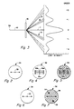
- Figure 1 utilizes diffraction in the order of minus one where light beam 39, in Figure 3 follows optical path 42, is diffracted by HOE 18 spectrally, according to wavelengths, along optical paths 13.
- Optical paths 13 of Figure 3 correspond to optical paths 43, 44 and 45 of Figure 1.
- HOE 20 is similar in construction to the HOE 18 except that it is rotated 180° about the optical axis of the HOE 18 or about its axis parallel to the grating lines of HOE 20.
- HOE 20 functions in the minus one order as illustrated in Figure 3.
- Optical paths 49, 50 and 51 of Figure 1 corresponds to a group of optical paths 13 of Figure 3, however, assuming that light is travelling from right to left through HOE 20 on optical paths 13 and 42 in Figure 3.
- the operation of HOE 20 is the converse of that of HOE 18 in Figure 1.
- Figure 7 illustrates an image 38 typically seen by observer 28 when the light of an image going through the fiber optics bundle 12 is not spectrally diffracted thus allowing the light beam of each pixel of the image to be transmitted through several fibers in the fiber optics bundle 12.
- a typical symptom of a non-diffracted image sent through the fiber optics bundle 12, is fixed pattern noise 58, or otherwise called the chicken wire effect, as illustrated in Figure 7.
- the fixed pattern noise 58 is due to the structure of fibers or bundles of them in the fiber optics bundle 12 viewed along with an image. Spots 54 and 56 of image 38 in Figure 7 are due to broken optical fibers.
- HOE 18 causes the pixels of image 38 at spots 54 and 56 to be transferred through other fibers of the fiber optics bundle 12 down several paths such as paths 46, 47 and 48 by spectral spreading the light beams in a similar way that light beam 39 of the image pixel is transmitted through several fibers. Said in another way, pixels to be conveyed by fibers to spots 54 and 56 are conveyed at different wavelengths by unbroken fibers and recombined by HOE 20. Pixels of the image 38 in the areas of 54 and 56 are then reconstructed resulting in a clear image 36 as illustrated in Figure 6.
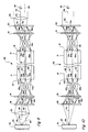
- Embodiment 80 of Figure 8 substantially eliminates that potential problem of light beam attenuation in the embodiment 10 of Figure 1.
- light beam 39b follows, among other paths, center optical paths 40, 42, 44 and 44a.
- Light beam 39b, following optical path 44a enters the flat end surface 14 of the fiber optics bundle 12 perpendicular to end 14, i.e., at no angle to axis 65, thus avoiding a dispersal in azimuth.
- the entry angle A with respect to axis 65 is reduced to zero, i.e., maintaining zero deviation of center light beam 39b, by utilizing additional HOE diffraction gratings 19 and 21.
- Light beam 39b exits end surface 16 parallel to axis 65.
- optical paths 44a and 50 are parallel to axis 65. Also, this embodiment 80, as applied to a straight fibers optics bundle 12, has center optical paths 40, 42, 52 and 53 that are in line with one another.
- light beam 39 follows optical path 40 through optics 22, onto path 42, and impinges upon HOE 18.
- Light beam 39 is spectrally diffracted into light beams 39a, 39b and 39c which follow optical paths 43, 44 and 45, respectively. This spectral diffraction is of the minus one order, as described above in conjunction with Figure 3.
- HOE 19 diffracts light beams 39a, 39b and 39c, at different angles due to their differing wavelengths.
- Light beams 39a, 39b and 39c having been already spectrally dispersed according to wavelength by HOE 18, follow optical paths 43a, 44a and 45a, and impinge on end surface 14 at various fibers.
- Light beams 39a, 39b and 39c follow optical paths 46, 47 and 48, respectively, through the fiber optics bundle 12 onto end surface 16.
- HOE 21 diffracts light beams 39a, 39b and 39c at varying angles according to their wavelengths.
- the function of HOE 21 is the converse of HOE 19.
- HOE 21 is rotated 180° relative to the optical axis of HOE 19.
- Light beams 39a, 39b and 39c follow optical paths 49a, 50a, 51a, and impinge HOE 20 at a single point.
- Light beams 39a, 39b and 39c are recombined into light beam 39 at HOE 20, functioning conversely of HOE 18.
- Light beam 39 follows optical path 52 through imaging optics 24 onto optical path 53, and composes a pixel in image 36 to be viewed by observer 28.
- Figure 10 shows another embodiment 70 which is a version of embodiment 80 in Figure 8. Due to advanced technology and development of HOE's, optical powers of the imaging lens 22 and the collimating lens 24 of Figure 8 may be incorporated in HOE's 88 and 90, respectively, in Figure 9.
- Light beam 39 of a pixel in source image 26 from source 30 follows an optical path 40 and is focused and diffracted by HOE 88.
- light beam 39 is diffracted into a plurality of light beams 39a, 39b and 39c of various wavelengths and follow a plurality of optical paths 43, 44 and 45, and impinge on HOE 19, which further diffracts light beams 39a, 39b and 39c, to follow optical paths 43a, 44a, 45a, respectively, and impinge on surface end 14 of the fiber optics bundle 12.
- Light beams 39a, 39b and 39c go through fiber optics bundle 12 via a plurality of optical paths 46, 47 and 48, exit at surface end 16, and enter a plurality of optical paths 49, 50, and 51 to HOE 21, correspondingly.
- HOE 21 functions in the converse of HOE 19, similarly as in the embodiment 80 of Figure 8.
- HOE 21 diffracts light beams 39a, 39b, and 39c, which follow optical paths 49a, 50a, and 51a, and impinge on HOE 90.
- Light beams 39a, 39b and 39c are recombined into light beam 39 at HOE 90.
- Optical powers incorporated in HOE 90 collimate light beam 39 to follow a path 53 to compose a pixel in image 36 which is viewed by observer 28.
- the embodiment of Figure 1 may be modified so as to eliminate the need of focussing lens and imaging lens 24 by replacing HOE 18 and HOE 20, respectively, with HOE 88 and HOE 90 as described in embodiment 70 of Figure 10.
- HOE's in all of the embodiments described herein may be ordinary, blazed or other kinds. Blazed HOE's are designed for narrow bandwidths of light and optimized for efficiency at a certain order of diffraction. Ordinary HOE's may be preferred for wider bandwidth light transmission in fiber optics bundles. Other kinds of HOE's, with special features designed into them, may be utilized in the above illustrated and other embodiments of the invention as desired by the designer or user.
- This invention is a novel utilization of HOE technology for image enhancement in fiber optics transmission.
- This system is not complex and may be easily and inexpensively produced. Many obvious alterations may occur to those skilled in the art and this invention should not be limited by the specific disclosures used in connection with the preferred embodiments.
Landscapes
- Physics & Mathematics (AREA)
- General Physics & Mathematics (AREA)
- Optics & Photonics (AREA)
- Holo Graphy (AREA)
- Optical Fibers, Optical Fiber Cores, And Optical Fiber Bundles (AREA)
- Details Of Television Systems (AREA)
- Optical Communication System (AREA)
Applications Claiming Priority (2)
| Application Number | Priority Date | Filing Date | Title |
|---|---|---|---|
| US517387A | 1987-01-20 | 1987-01-20 | |
| US5173 | 1987-01-20 |
Publications (2)
| Publication Number | Publication Date |
|---|---|
| EP0275947A2 true EP0275947A2 (de) | 1988-07-27 |
| EP0275947A3 EP0275947A3 (de) | 1989-05-03 |
Family
ID=21714537
Family Applications (1)
| Application Number | Title | Priority Date | Filing Date |
|---|---|---|---|
| EP88100560A Withdrawn EP0275947A3 (de) | 1987-01-20 | 1988-01-16 | Bildverstärker für faseroptisches Transmissionssystem |
Country Status (3)
| Country | Link |
|---|---|
| EP (1) | EP0275947A3 (de) |
| JP (1) | JPS63214708A (de) |
| IL (1) | IL84527A0 (de) |
Cited By (5)
| Publication number | Priority date | Publication date | Assignee | Title |
|---|---|---|---|---|
| WO1989003067A1 (en) * | 1987-09-23 | 1989-04-06 | Michael Burney | Holographic display transmitting device |
| GB2227102A (en) * | 1989-01-13 | 1990-07-18 | Ferranti Int Signal | Optical fibre link between transceivers containing holographic optical elements |
| EP0430911A1 (de) * | 1989-10-27 | 1991-06-05 | Telefonaktiebolaget L M Ericsson | Optische Verbindungsvorrichtung |
| AU691845B2 (en) * | 1995-01-09 | 1998-05-28 | Michael Burney | Holographic display transmitting device |
| KR100568655B1 (ko) * | 1998-02-13 | 2006-04-07 | 이 아이 듀폰 디 네모아 앤드 캄파니 | 항미생물제를 포함하는 시스-코아 폴리에스테르 섬유 |
Family Cites Families (3)
| Publication number | Priority date | Publication date | Assignee | Title |
|---|---|---|---|---|
| FR2504758A1 (fr) * | 1981-04-27 | 1982-10-29 | Thomson Csf | Dispositif de transport d'image lumineuse par cable optique et utilisation pour la prise de vues d'images video |
| JPS58168012A (ja) * | 1982-03-29 | 1983-10-04 | Olympus Optical Co Ltd | イメ−ジガイドフアイバ観察装置 |
| EP0134930A1 (de) * | 1983-06-30 | 1985-03-27 | Hitachi, Ltd. | Vorrichtung zur optischen Bildübertragung |
-
1987
- 1987-11-19 IL IL84527A patent/IL84527A0/xx unknown
-
1988
- 1988-01-16 EP EP88100560A patent/EP0275947A3/de not_active Withdrawn
- 1988-01-20 JP JP63008575A patent/JPS63214708A/ja active Pending
Cited By (7)
| Publication number | Priority date | Publication date | Assignee | Title |
|---|---|---|---|---|
| WO1989003067A1 (en) * | 1987-09-23 | 1989-04-06 | Michael Burney | Holographic display transmitting device |
| GB2227102A (en) * | 1989-01-13 | 1990-07-18 | Ferranti Int Signal | Optical fibre link between transceivers containing holographic optical elements |
| GB2227102B (en) * | 1989-01-13 | 1993-03-24 | Ferranti Int Signal | Optical coupler with a fibre link between transceivers |
| EP0430911A1 (de) * | 1989-10-27 | 1991-06-05 | Telefonaktiebolaget L M Ericsson | Optische Verbindungsvorrichtung |
| US5140657A (en) * | 1989-10-27 | 1992-08-18 | Telefonaktiebolaget L M Ericsson | Diffraction optical coupler |
| AU691845B2 (en) * | 1995-01-09 | 1998-05-28 | Michael Burney | Holographic display transmitting device |
| KR100568655B1 (ko) * | 1998-02-13 | 2006-04-07 | 이 아이 듀폰 디 네모아 앤드 캄파니 | 항미생물제를 포함하는 시스-코아 폴리에스테르 섬유 |
Also Published As
| Publication number | Publication date |
|---|---|
| IL84527A0 (en) | 1988-04-29 |
| EP0275947A3 (de) | 1989-05-03 |
| JPS63214708A (ja) | 1988-09-07 |
Similar Documents
| Publication | Publication Date | Title |
|---|---|---|
| DE69411711T2 (de) | Auf dem kopf getragenes anzeigesystem mit diffraktiven optischen elementen | |
| DE60314306T2 (de) | Kompaktes Beleuchtungssystem und damit versehene Projektionsanzeigevorrichtung | |
| US6088102A (en) | Display apparatus including grating light-valve array and interferometric optical system | |
| EP0968448B1 (de) | Beleuchtungssystem | |
| KR0180794B1 (ko) | 비디오 투사장치 | |
| US4735473A (en) | Device for optical-cable transport and combination of light images | |
| DE69428716T2 (de) | Projektionssystem für bewegende bilder | |
| DE212017000261U1 (de) | Optisches System mit kompaktem Kollimator-Bildprojektor | |
| DE60029625T2 (de) | Anzeigegerät | |
| US7495833B2 (en) | Scanned beam source and systems using a scanned beam source for producing a wavelength-compensated composite beam of light | |
| US12066629B2 (en) | Image display apparatus and head-mounted display | |
| JPS62195975A (ja) | 映像バ−装置用の画素間の空白抑制装置 | |
| EP3673316A1 (de) | Gekrümmter lichtleiter, abbildungsoptik und hmd | |
| EP0275947A2 (de) | Bildverstärker für faseroptisches Transmissionssystem | |
| DE102013200443B4 (de) | Projektionsfläche für eine Blickfeldanzeige, Blickfeldanzeige für ein Fahrzeug und Verfahren zum Projizieren eines Bildes | |
| US20030103194A1 (en) | Display apparatus including RGB color combiner and 1D light valve relay including schlieren filter | |
| US20150042967A1 (en) | Projection head for a laser projector | |
| JP4185264B2 (ja) | 偏光方向制御素子及び露光装置 | |
| US5579177A (en) | Optical dispersion apparatus and method | |
| JPH08234246A (ja) | 光学クロスバースイッチ組立体 | |
| DE102013203915A1 (de) | Projektionsfläche für eine Blickfeldanzeige, Blickfeldanzeige für ein Fahrzeug und Verfahren zum Betreiben einer Projektionsfläche | |
| JPH11249181A (ja) | 偏向装置、使用方法およびビデオシステム | |
| DE102022116121A1 (de) | Kaskadierte eyebox-aufweitung in erweiterte-realitätbildprojektionsvorrichtungen | |
| US5134520A (en) | Double directional image development head-up display optical system | |
| DE112021002517T5 (de) | Anzeigevorrichtung |
Legal Events
| Date | Code | Title | Description |
|---|---|---|---|
| PUAI | Public reference made under article 153(3) epc to a published international application that has entered the european phase |
Free format text: ORIGINAL CODE: 0009012 |
|
| AK | Designated contracting states |
Kind code of ref document: A2 Designated state(s): DE FR GB IT |
|
| PUAL | Search report despatched |
Free format text: ORIGINAL CODE: 0009013 |
|
| AK | Designated contracting states |
Kind code of ref document: A3 Designated state(s): DE FR GB IT |
|
| STAA | Information on the status of an ep patent application or granted ep patent |
Free format text: STATUS: THE APPLICATION IS DEEMED TO BE WITHDRAWN |
|
| 18D | Application deemed to be withdrawn |
Effective date: 19891106 |