EP0275902A2 - Device for dragging along trunks or suchlike - Google Patents
Device for dragging along trunks or suchlike Download PDFInfo
- Publication number
- EP0275902A2 EP0275902A2 EP88100351A EP88100351A EP0275902A2 EP 0275902 A2 EP0275902 A2 EP 0275902A2 EP 88100351 A EP88100351 A EP 88100351A EP 88100351 A EP88100351 A EP 88100351A EP 0275902 A2 EP0275902 A2 EP 0275902A2
- Authority
- EP
- European Patent Office
- Prior art keywords
- boom
- cross member
- strut
- support feet
- axis
- Prior art date
- Legal status (The legal status is an assumption and is not a legal conclusion. Google has not performed a legal analysis and makes no representation as to the accuracy of the status listed.)
- Granted
Links
Images


Classifications
-
- A—HUMAN NECESSITIES
- A01—AGRICULTURE; FORESTRY; ANIMAL HUSBANDRY; HUNTING; TRAPPING; FISHING
- A01G—HORTICULTURE; CULTIVATION OF VEGETABLES, FLOWERS, RICE, FRUIT, VINES, HOPS OR SEAWEED; FORESTRY; WATERING
- A01G23/00—Forestry
- A01G23/003—Collecting felled trees
- A01G23/006—Log skidders
Definitions
- the invention relates to a device for pre-delivering logs or the like, which or the like to a logging vehicle having a winch or the like. can be attached, with a crane-like swiveling boom, over which the pull rope of the winch is guided.
- a device is known on a rear device designed as a tracked vehicle.
- the boom serves as a tensioning device for the traction rope, on which the logs to be moved are transported in the manner of a cable car.
- This known device is very complex and very difficult to handle, since the cable car must be rebuilt in each of the alleys, especially when backing logs lying in alleys, which makes a new attachment of a counter role necessary.
- the object of the invention is to propose a device of the type mentioned with the back or the like of logs preferably lying in alleys or the like. is possible in a simple manner without having to move the logging vehicle from alley to alley in each case.
- the object is achieved in that the boom or the like on a with the lifting device, the three-point hitch. of Rear vehicle connectable cross member is pivotally arranged about an axis extending in the horizontal direction, and that the cross member has at its ends support feet for support on the floor.
- the boom is advantageously connected to a hydraulically actuated pressure cylinder.
- the pressure cylinder is preferably connected to the cross member and the piston rod of the pressure cylinder to the boom.
- the support feet are preferably slidable and fixable in the vertical direction on the cross member. In a further advantageous embodiment, the support feet are displaceable and fixable in the horizontal direction on the cross member.
- the cross member is preferably hollow on the inside and the support feet are arranged on cross struts which are displaceably guided in the interior of the cross member.
- the support feet advantageously have bottom plates laterally projecting from the support feet at their lower ends.
- the support feet and / or the cross struts can preferably be actuated hydraulically.
- the boom is designed as a longwall.
- the boom preferably has two struts connected to one another at an acute angle, of which the shorter strut is connected to the other end of the longer strut via an oblique strut extending at an obtuse angle.
- the shorter strut is preferably connected at its end to the longer strut by a support strut arranged at right angles to the longer strut.
- the boom preferably carries a rope guide with rollers at its end.
- the cable guide is preferably arranged on the boom so as to be pivotable independently of one another about an axis running essentially parallel to the longitudinal direction of the boom.
- a cable deflection roller at the height of the cable winch is advantageously arranged on the boom.
- Two cantilevers are preferably arranged on the cross member at a distance from one another pivotable about the axis.
- the cross member (3) is connected to the three-point hitch (1) of a rear vehicle (2) a cross member (3) extending in the horizontal direction.
- the cross member (3) is hollow on the inside.
- cross struts (4) (Fig. 2 and 4) are arranged displaceably, which have hydraulically displaceable and fixable support feet (5) near their ends in the vertical direction.
- the support feet (5) have base plates (6) at their lower end.
- the brackets (8) are designed as a strut with two struts (9) and (10) extending at an acute angle to one another.
- the longer strut (9) can be pivoted about the axis (7).
- 1 to 4 show the shorter strut (10) Via an oblique strut (11) running at an obtuse angle to it, at a distance from the longer strut (9), is pivotable about the axis (7).
- the longer strut (9) is further connected to the end of the shorter strut (10) and the oblique strut (11) by a support strut (12) arranged at right angles to the longer strut.
- This design gives the boom (8) high stability in all directions.
- a hydraulically actuated pressure cylinder is also connected to the cross member (3), the piston rod (14) of which is connected to the oblique strut (11).
- Two independently operable cable winches (15) are arranged on the logging vehicle (2), the traction cables (16) of which are guided over cable deflection rollers (17) arranged on the brackets (8) approximately at the height of the cable winches (15).
- the ends of the arms (8) have rope guides (18) which have rollers and can be pivoted about axes running in the longitudinal direction of the arms.
- the cross member (3) is raised above the three-point hitch (1), as shown in FIGS. 1 and 2.
- the cross struts (4) are inserted into the cross member (3), and the support feet (5) are also raised.
- the booms (8) are swiveled forward with the help of the pressure cylinders (12) to the logging vehicle (2).
- the cross member (3) is pivoted downwards so that the support feet (5) are firmly supported on the floor.
- the arms (8) can now be pivoted independently of one another into the desired position with the aid of the pressure cylinder (12), so that over both Outrigger can be used to independently deliver the logs using the pull ropes.
- the device according to the invention is inexpensive to manufacture, since it can be attached to a conventional rear device and no special winch is required.
- the fact that the device can be supported on the floor results in a high stability with a low center of gravity, in particular also because the backing vehicle (2) serves as a counterweight.
- the low position of the center of gravity also allows a longer length of the boom (8), so that long ranges can be achieved with the boom and only an occasional movement of the skidding vehicle (2) is necessary.
Landscapes
- Life Sciences & Earth Sciences (AREA)
- Biodiversity & Conservation Biology (AREA)
- Ecology (AREA)
- Forests & Forestry (AREA)
- Environmental Sciences (AREA)
- Jib Cranes (AREA)
- Forklifts And Lifting Vehicles (AREA)
- Warehouses Or Storage Devices (AREA)
- Acyclic And Carbocyclic Compounds In Medicinal Compositions (AREA)
- Eye Examination Apparatus (AREA)
Abstract
Bei einer bekannten derartigen Vorrichtung ist auf einem als Kettenfahrzeug ausgebildeten Rückegerät ein schwenkbarer Ausleger angeordnet, der als Spannvorrichtung für ein Zugseil dient, an dem nach Art einer Seilbahn die zu rückenden Stämme transportiert werden. Die neue Vorrichtung soll ein Rücken von vorzugsweise in Gassen liegenden Holzstämmen o.dgl. auf einfache Art und Weise ermöglichen, ohne daß dabei jeweils ein Versetzen des Rückefahrzeuges von Gasse zu Gasse notwendig ist.In a known device of this type, a swiveling boom is arranged on a rear device designed as a tracked vehicle, which serves as a tensioning device for a traction rope, on which the logs to be moved are transported in the manner of a cable car. The new device is intended to be a back of logs or the like, preferably lying in alleys. enable in a simple manner without the need to move the logging vehicle from alley to alley.
Die an ein Rückefahrzeug (2) o.dgl. anbaubare Vorrichtung weist einen Ausleger (8) für das Zugseil auf, der auf einem mit der Hubvorrichtung, der Dreipunktanhängung o.dgl. des Rückefahrzeuges (2) verbindbaren Querträger (3) um eine in horizontaler Richtung verlaufende Achse (7) schwenkbar angeordnet ist, wobei der Querträger (3) an seinen Enden Stützfüße (5) zum Abstützen auf den Boden hat. 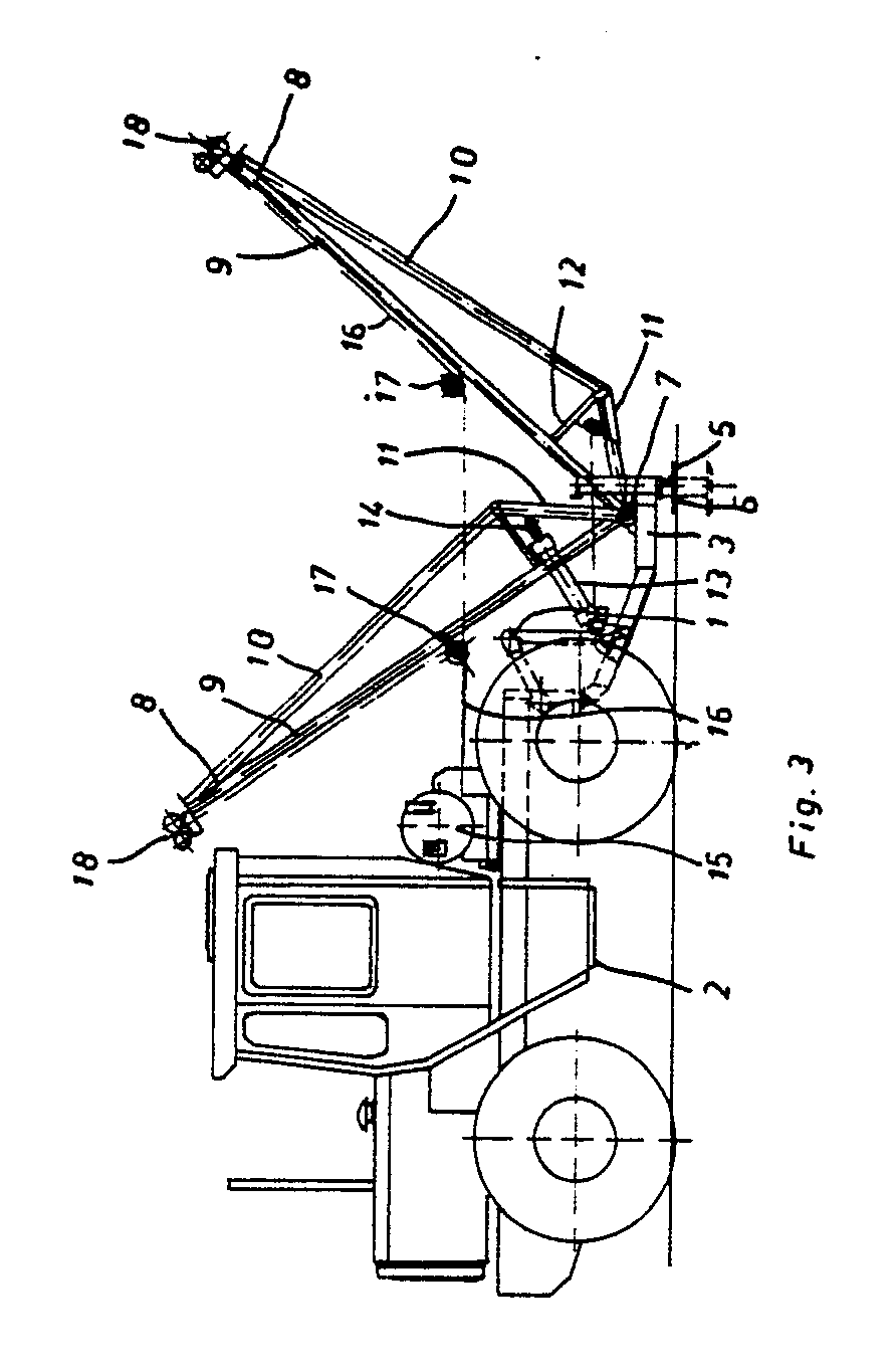
Description
Die Erfindung betrifft eine Vorrichtung zum Vorliefern von Holzstämmen o.dgl., die an ein eine Seilwinde aufweisendes Rückefahrzeug o.dgl. anbaubar ist, mit einem kranartigen schwenkbaren Ausleger, über den das Zugseil der Seilwinde geführt ist.The invention relates to a device for pre-delivering logs or the like, which or the like to a logging vehicle having a winch or the like. can be attached, with a crane-like swiveling boom, over which the pull rope of the winch is guided.
Aus der SU-PS 435 969 ist eine derartige Vorrichtung auf einem als Kettenfahrzeug ausgebildeten Rückegerät bekannt. Bei dieser Vorrichtung dient der Ausleger als Spannvorrichtung für das Zugseil, an dem nach Art einer Seilbahn die zu rückenden Stämme transportiert werden.From SU-PS 435 969 such a device is known on a rear device designed as a tracked vehicle. In this device, the boom serves as a tensioning device for the traction rope, on which the logs to be moved are transported in the manner of a cable car.
Diese bekannte Vorrichtung ist sehr aufwendig und sehr mühsam handhabbar, da insbesondere beim Rücken von in Gassen liegenden Holzstämmen die Seilbahn jeweils in den Gassen neu aufgebaut werden muß, was ein neues Befestigen einer Gegenrolle notwendig macht.This known device is very complex and very difficult to handle, since the cable car must be rebuilt in each of the alleys, especially when backing logs lying in alleys, which makes a new attachment of a counter role necessary.
Die Aufgabe der Erfindung besteht darin, eine Vorrichtung der eingangs genannten Art vorzuschlagen, mit der ein Rücken von vorzugsweise in Gassen liegenden Holzstämmen o.dgl. auf einfache Art möglich ist, ohne daß jeweils ein Versetzen des Rückefahrzeuges von Gasse zu Gasse notwendig ist.The object of the invention is to propose a device of the type mentioned with the back or the like of logs preferably lying in alleys or the like. is possible in a simple manner without having to move the logging vehicle from alley to alley in each case.
Die Aufgabe wird dadurch gelöst, daß der Ausleger auf einem mit der Hubvorrichtung, der Dreipunktanhängung o.dgl. des Rückefahrzeuges verbindbaren Querträger um eine in horizontaler Richtung verlaufende Achse schwenkbar angeordnet ist, und daß der Querträger an seinen Enden Stützfüße zum Abstützen auf dem Boden hat.The object is achieved in that the boom or the like on a with the lifting device, the three-point hitch. of Rear vehicle connectable cross member is pivotally arranged about an axis extending in the horizontal direction, and that the cross member has at its ends support feet for support on the floor.
Vorteilhaft ist der Ausleger mit einem hydraulisch betätigbaren Druckzylinder verbunden. Vorzugsweise ist der Druckzylinder mit dem Querträger und die Kolbenstange des Druckzylinders mit dem Ausleger verbunden.The boom is advantageously connected to a hydraulically actuated pressure cylinder. The pressure cylinder is preferably connected to the cross member and the piston rod of the pressure cylinder to the boom.
Die Stützfüße sind vorzugsweise in vertikaler Richtung am Quertäger verschiebbar und festlegbar geführt. Bei einer weiteren vorteilhaften Ausführungsform sind die Stützfüße in horizontaler Richtung am Querträger verschiebbar und festlegbar geführt.The support feet are preferably slidable and fixable in the vertical direction on the cross member. In a further advantageous embodiment, the support feet are displaceable and fixable in the horizontal direction on the cross member.
Vorzugsweise ist der Querträger innen hohl ausgebildet und sind die Stützfüße an Querstreben angeordnet, die im Inneren des Querträgers verschiebbar geführt sind. Die Stützfüße weisen vorteilhaft an ihren unteren Enden die Stützfüße seitlich überragende Bodenplatten auf. Die Stützfüße und/oder die Querstreben sind vorzugsweise hydraulisch betätigbar.The cross member is preferably hollow on the inside and the support feet are arranged on cross struts which are displaceably guided in the interior of the cross member. The support feet advantageously have bottom plates laterally projecting from the support feet at their lower ends. The support feet and / or the cross struts can preferably be actuated hydraulically.
Bei einer vorteilhaften Ausführungsform ist der Ausleger als Strebwerk ausgebildet. Vorzugsweise hat der Ausleger zwei im spitzen Winkel miteinander verbundene Streben, von denen die kürzere Strebe über eine im stumpfen Winkel dazu verlaufende Schrägstrebe mit dem anderen Ende der längeren Strebe verbunden ist. Vorzugsweise ist die kürzere Strebe an ihrem Ende durch eine im rechten Winkel zur längeren Strebe angeordnete Stützstrebe mit der längeren Strebe verbunden.In an advantageous embodiment, the boom is designed as a longwall. The boom preferably has two struts connected to one another at an acute angle, of which the shorter strut is connected to the other end of the longer strut via an oblique strut extending at an obtuse angle. The shorter strut is preferably connected at its end to the longer strut by a support strut arranged at right angles to the longer strut.
Vorzugsweise trägt der Ausleger an seinem Ende eine Rollen aufweisende Seilführung. Vorzugsweise ist die Seilführung um eine im wesentlichen parallel zur Auslegerlängsrichtung verlaufende Achse unabhängig voneinander schwenkbar am Ausleger angeordnet.The boom preferably carries a rope guide with rollers at its end. The cable guide is preferably arranged on the boom so as to be pivotable independently of one another about an axis running essentially parallel to the longitudinal direction of the boom.
Vorteilhaft ist am Ausleger eine Seilumlenkrolle in Höhe der Seilwinde angeordnet.A cable deflection roller at the height of the cable winch is advantageously arranged on the boom.
Vorzugsweise sind auf dem Querträger zwei Ausleger im Abstand zueinander um die Achse schwenkbar angeordnet.Two cantilevers are preferably arranged on the cross member at a distance from one another pivotable about the axis.
Die Erfindung ist in den Zeichnungen beispielhaft dargestellt. Es zeigen:
- Fig. 1 die erfindungsgemäße Vorrichtung in Transportstellung in Seitenansicht,
- Fig. 2 die Vorrichtung nach Fig. 1 in Rückansicht,
- Fig. 3 die Vorrichtung in Arbeitsstellung in Seitenansicht und
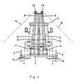
- Fig. 4 die Vorrichtung nach Fig. 3 in Rückansicht.
- 1 shows the device according to the invention in transport position in a side view,
- 2 shows the device according to FIG. 1 in rear view,
- Fig. 3 shows the device in working position in side view
- Fig. 4 shows the device of FIG. 3 in rear view.
Nach den Fig. 1 bis 4 ist mit der Dreipunktanhängung (1) eines Rückefahrzeuges (2) ein in horizontaler Richtung verlaufender Querträger (3) verbunden. Der Querträger (3) ist innen hohl ausgebildet. Im Inneren des Querträgers (3) sind Querstreben (4) (Fig. 2 und 4) verschiebbar angeordnet, die nahe ihren Enden in vertikaler Richtung hydraulisch verschiebbare und festlegbare Stützfüße (5) haben. Die Stützfüße (5) weisen an ihrem unteren Ende Bodenplatten (6) auf.1 to 4 is connected to the three-point hitch (1) of a rear vehicle (2) a cross member (3) extending in the horizontal direction. The cross member (3) is hollow on the inside. In the interior of the cross member (3) cross struts (4) (Fig. 2 and 4) are arranged displaceably, which have hydraulically displaceable and fixable support feet (5) near their ends in the vertical direction. The support feet (5) have base plates (6) at their lower end.
Auf dem Querträger (3) sind um eine in horizontaler Richtung verlaufende Achse (7) (Fig. 1 und 3) zwei im Abstand zueinander angeordnete Ausleger (8) schwenkbar angeordnet. Die Ausleger (8) sind als Strebwerk mit zwei im spitzen Winkel zueinander verlaufenden Streben (9) und (10) ausgebildet. Die längere Strebe (9) ist um die Achse (7) schwenkbar. Wie die Fig. 1 bis 4 zeigen, ist die kürzere Strebe (10) über eine im stumpfen Winkel zu ihr verlaufende Schrägstrebe (11) im Abstand von der längeren Strebe (9) um die Achse (7) schwenkbar angeordnet. Die längere Strebe (9) ist ferner durch eine im rechten Winkel zur längeren Strebe angeordnete Stützstrebe (12) mit dem Ende der kürzeren Strebe (10) und der Schrägstrebe (11) verbunden. Durch diese Ausbildung erhalten die Ausleger (8) in allen Richtungen eine hohe Stabilität.On the cross member (3) about a horizontal axis (7) (Fig. 1 and 3) two spaced-apart arms (8) are arranged pivotally. The brackets (8) are designed as a strut with two struts (9) and (10) extending at an acute angle to one another. The longer strut (9) can be pivoted about the axis (7). 1 to 4 show the shorter strut (10) Via an oblique strut (11) running at an obtuse angle to it, at a distance from the longer strut (9), is pivotable about the axis (7). The longer strut (9) is further connected to the end of the shorter strut (10) and the oblique strut (11) by a support strut (12) arranged at right angles to the longer strut. This design gives the boom (8) high stability in all directions.
Mit dem Querträger (3) ist weiterhin ein hydraulisch betätigbarer Druckzylinder verbunden, dessen Kolbenstange (14) mit der Schrägstrebe (11) verbunden ist.A hydraulically actuated pressure cylinder is also connected to the cross member (3), the piston rod (14) of which is connected to the oblique strut (11).
Auf dem Rückefahrzeug (2) sind zwei unabhängig voneinander betätigbare Seilwinden (15) angeordnet, deren Zugseile (16) über an den Auslegern (8) etwa in Höhe der Seilwinden (15) angeordnete Seilumlenkrollen (17) geführt sind.Two independently operable cable winches (15) are arranged on the logging vehicle (2), the traction cables (16) of which are guided over cable deflection rollers (17) arranged on the brackets (8) approximately at the height of the cable winches (15).
Die Ausleger (8) tragen an ihren Enden Rollen aufweisende Seilführungen (18), die um in Auslegerlängsrichtung verlaufende Achsen schwenkbar sind.The ends of the arms (8) have rope guides (18) which have rollers and can be pivoted about axes running in the longitudinal direction of the arms.
Zum Transport der Vorrichtung ist der Querträger (3) über die Dreipunktanhängung (1) angehoben, wie dies Fig. 1 und 2 zeigen. Die Querstreben (4) sind in den Querträger (3) eingeschoben, ebenso sind die Stützfüße (5) angehoben. Die Ausleger (8) sind mit Hilfe der Druckzylinder (12) nach vorne zum Rückefahrzeug (2) geschwenkt.To transport the device, the cross member (3) is raised above the three-point hitch (1), as shown in FIGS. 1 and 2. The cross struts (4) are inserted into the cross member (3), and the support feet (5) are also raised. The booms (8) are swiveled forward with the help of the pressure cylinders (12) to the logging vehicle (2).
Zum Rücken wird nach Ausziehen der Querstreben (4) und dem Absetzen der Stützfüße (5) der Querträger (3) nach unten geschwenkt, so daß sich die Stützfüße (5) fest auf dem Boden abstützen. Die Ausleger (8) können nun mit Hilfe der Druckzylinder (12) unabhängig voneinander in die jeweils gewünschte Position geschwenkt werden, so daß über beide Ausleger mit Hilfe der Zugseile unabhängig voneinander das Vorliefern der Holzstämme erfolgen kann.After pulling out the cross struts (4) and putting down the support feet (5), the cross member (3) is pivoted downwards so that the support feet (5) are firmly supported on the floor. The arms (8) can now be pivoted independently of one another into the desired position with the aid of the pressure cylinder (12), so that over both Outrigger can be used to independently deliver the logs using the pull ropes.
Die erfindungsgemäße Vorrichtung ist kostengünstig herstellbar, da sie an ein übliches Rückegerät anbaubar ist und keine besondere Seilwinde notwendig ist. Dadurch, daß die Vorrichtung auf dem Boden abstützbar ist, ergibt sich eine hohe Stabilität bei tiefliegendem Schwerpunkt, insbesondere auch deshalb, weil das Rückefahrzeug (2) als Gegengewicht dient. Die tiefe Lage des Schwerpunktes ermöglicht zudem eine größere Länge der Ausleger (8), so daß mit den Auslegern große Reichweiten erzielbar sind und nur ein gelegentliches Versetzen des Rückefahrzeuges (2) notwendig ist.The device according to the invention is inexpensive to manufacture, since it can be attached to a conventional rear device and no special winch is required. The fact that the device can be supported on the floor results in a high stability with a low center of gravity, in particular also because the backing vehicle (2) serves as a counterweight. The low position of the center of gravity also allows a longer length of the boom (8), so that long ranges can be achieved with the boom and only an occasional movement of the skidding vehicle (2) is necessary.
Claims (10)
Priority Applications (1)
| Application Number | Priority Date | Filing Date | Title |
|---|---|---|---|
| AT88100351T ATE68663T1 (en) | 1987-01-17 | 1988-01-13 | DEVICE FOR PRE-DELIVERY OF WOOD LOGS O. DGL. |
Applications Claiming Priority (2)
| Application Number | Priority Date | Filing Date | Title |
|---|---|---|---|
| DE19873701244 DE3701244A1 (en) | 1987-01-17 | 1987-01-17 | DEVICE FOR DELIVERING WOOD STAMPS OR THE LIKE. |
| DE3701244 | 1987-01-17 |
Publications (3)
| Publication Number | Publication Date |
|---|---|
| EP0275902A2 true EP0275902A2 (en) | 1988-07-27 |
| EP0275902A3 EP0275902A3 (en) | 1989-03-01 |
| EP0275902B1 EP0275902B1 (en) | 1991-10-23 |
Family
ID=6318991
Family Applications (1)
| Application Number | Title | Priority Date | Filing Date |
|---|---|---|---|
| EP88100351A Expired - Lifetime EP0275902B1 (en) | 1987-01-17 | 1988-01-13 | Device for dragging along trunks or suchlike |
Country Status (3)
| Country | Link |
|---|---|
| EP (1) | EP0275902B1 (en) |
| AT (1) | ATE68663T1 (en) |
| DE (2) | DE3701244A1 (en) |
Cited By (3)
| Publication number | Priority date | Publication date | Assignee | Title |
|---|---|---|---|---|
| DE29622374U1 (en) * | 1996-12-23 | 1997-04-17 | Maurer jun., Karl, 82467 Garmisch-Partenkirchen | Cantilever arm for forest winches |
| CN109186352A (en) * | 2018-10-31 | 2019-01-11 | 航宇救生装备有限公司 | Buffer system takes dress march method |
| US11267300B2 (en) * | 2019-06-26 | 2022-03-08 | Deere & Company | Hitch mechanism |
Families Citing this family (1)
| Publication number | Priority date | Publication date | Assignee | Title |
|---|---|---|---|---|
| DE10034336C2 (en) * | 2000-07-14 | 2003-01-02 | Welte Fahrzeugbau Gmbh | Cable winch for bringing wood into the forest |
Family Cites Families (11)
| Publication number | Priority date | Publication date | Assignee | Title |
|---|---|---|---|---|
| US1873433A (en) * | 1930-09-18 | 1932-08-23 | American Coach & Body Company | Crane |
| US2216263A (en) * | 1940-01-29 | 1940-10-01 | Wooldridge Mfg Company | Fair lead construction |
| DE873125C (en) * | 1950-03-24 | 1953-04-09 | Hinrich Weyhausen | Crane mounted on a tractor |
| US2720380A (en) * | 1953-08-11 | 1955-10-11 | Charles E Dyer | Logging boom |
| US2834574A (en) * | 1955-01-24 | 1958-05-13 | Charles E Sentman | Winch assembly |
| FR1227646A (en) * | 1959-06-06 | 1960-08-22 | Adjustable jib mounted on a three-point tractor, with PTO on an agricultural tractor, or on an industrial handling self-propelled tractor | |
| SU435969A1 (en) * | 1973-01-09 | 1974-07-15 | проектно конструкторского института механизации , энергетики лесной промышленности | |
| US4226331A (en) * | 1977-08-08 | 1980-10-07 | Dumond Duane I | Hydraulically actuated hoist for tractors having a conventional three point hitch |
| SE426641B (en) * | 1981-06-10 | 1983-02-07 | Forshaga Mek Verk Ab | Arrangement for so-called three-point coupling for hydraulic cranes, for example, on tractors |
| US4411080A (en) * | 1981-08-21 | 1983-10-25 | Mann Donald B | High-lead yarder rake |
| DE3426128C1 (en) * | 1984-07-16 | 1986-03-06 | Gebr. Jäckle GmbH Maschinen- & Gerätebau, 7709 Hilzingen | Device for pre-delivering logs |
-
1987
- 1987-01-17 DE DE19873701244 patent/DE3701244A1/en active Granted
-
1988
- 1988-01-13 DE DE8888100351T patent/DE3865682D1/en not_active Expired - Lifetime
- 1988-01-13 EP EP88100351A patent/EP0275902B1/en not_active Expired - Lifetime
- 1988-01-13 AT AT88100351T patent/ATE68663T1/en not_active IP Right Cessation
Cited By (3)
| Publication number | Priority date | Publication date | Assignee | Title |
|---|---|---|---|---|
| DE29622374U1 (en) * | 1996-12-23 | 1997-04-17 | Maurer jun., Karl, 82467 Garmisch-Partenkirchen | Cantilever arm for forest winches |
| CN109186352A (en) * | 2018-10-31 | 2019-01-11 | 航宇救生装备有限公司 | Buffer system takes dress march method |
| US11267300B2 (en) * | 2019-06-26 | 2022-03-08 | Deere & Company | Hitch mechanism |
Also Published As
| Publication number | Publication date |
|---|---|
| DE3865682D1 (en) | 1991-11-28 |
| EP0275902B1 (en) | 1991-10-23 |
| EP0275902A3 (en) | 1989-03-01 |
| ATE68663T1 (en) | 1991-11-15 |
| DE3701244A1 (en) | 1988-07-28 |
| DE3701244C2 (en) | 1988-11-17 |
Similar Documents
| Publication | Publication Date | Title |
|---|---|---|
| DE69229748T2 (en) | System for storing and handling drill pipes for drilling rigs | |
| DE4447860C2 (en) | Towing vehicle for maneuvering aircraft | |
| DE7529603U (en) | MATERIAL HANDLING DEVICE ATTACHED TO A TRACTOR | |
| DE2525867A1 (en) | CRANE | |
| DE602005003560T2 (en) | Diagnostic device for a trailer trailer coupling of a vehicle | |
| DE2250428A1 (en) | LIFTING EQUIPMENT FOR VEHICLES | |
| DE1281128B (en) | Mobile multi-purpose crane | |
| EP0564687B1 (en) | Towing device | |
| DE1506519C2 (en) | Telescopic boom | |
| EP0275902A2 (en) | Device for dragging along trunks or suchlike | |
| DE102007049179B3 (en) | Device for holding a coffin in a hearse comprises a lower loading floor, further loading floors, a middle loading floor and an upper loading floor which can be adjusting in height and locked into position | |
| DE3425428C2 (en) | Vehicle for transporting prefabricated building parts | |
| AT401310B (en) | VEHICLE, IN PARTICULAR TRAILER VEHICLE, CARRETTE OD. DGL. | |
| DE1941940B2 (en) | Vehicle with lifting device for large-volume boxes, preferably made of concrete with recesses in the floor for telescopically adjustable legs of the lifting device | |
| DE3033601A1 (en) | SKI LIFT | |
| DE670577C (en) | Towing vehicle, especially for damaged vehicles | |
| DE912803C (en) | Auxiliary device for setting and stealing stamps | |
| DE19809332C2 (en) | Winding device | |
| DE4335855A1 (en) | Working stage to be used in the roadway | |
| DE3624247A1 (en) | Vehicle for transporting ready-made concrete garages | |
| DE3601905A1 (en) | WORK VEHICLE, ESPECIALLY MOUNTAIN VEHICLE | |
| AT373943B (en) | ADDITIONAL DEVICE FOR THE FRONT LOADER OF A TRACTOR | |
| DE1946616C (en) | An agricultural tractor with a single or multiple drum cable winch at the rear | |
| DD287919A5 (en) | PROCESSABLE EXCHANGE DEVICE FOR GRAVILLE ROLLING STATIONS | |
| DE2006724C (en) | Drilling device mounted on a vehicle |
Legal Events
| Date | Code | Title | Description |
|---|---|---|---|
| PUAI | Public reference made under article 153(3) epc to a published international application that has entered the european phase |
Free format text: ORIGINAL CODE: 0009012 |
|
| AK | Designated contracting states |
Kind code of ref document: A2 Designated state(s): AT BE CH DE FR LI LU |
|
| PUAL | Search report despatched |
Free format text: ORIGINAL CODE: 0009013 |
|
| AK | Designated contracting states |
Kind code of ref document: A3 Designated state(s): AT BE CH DE FR LI LU |
|
| 17P | Request for examination filed |
Effective date: 19890123 |
|
| 17Q | First examination report despatched |
Effective date: 19900924 |
|
| GRAA | (expected) grant |
Free format text: ORIGINAL CODE: 0009210 |
|
| AK | Designated contracting states |
Kind code of ref document: B1 Designated state(s): AT BE CH DE FR LI LU |
|
| REF | Corresponds to: |
Ref document number: 68663 Country of ref document: AT Date of ref document: 19911115 Kind code of ref document: T |
|
| PGFP | Annual fee paid to national office [announced via postgrant information from national office to epo] |
Ref country code: FR Payment date: 19911121 Year of fee payment: 5 |
|
| REF | Corresponds to: |
Ref document number: 3865682 Country of ref document: DE Date of ref document: 19911128 |
|
| PGFP | Annual fee paid to national office [announced via postgrant information from national office to epo] |
Ref country code: LU Payment date: 19911210 Year of fee payment: 5 |
|
| PGFP | Annual fee paid to national office [announced via postgrant information from national office to epo] |
Ref country code: CH Payment date: 19911211 Year of fee payment: 5 Ref country code: AT Payment date: 19911211 Year of fee payment: 5 |
|
| PGFP | Annual fee paid to national office [announced via postgrant information from national office to epo] |
Ref country code: BE Payment date: 19920116 Year of fee payment: 5 |
|
| ET | Fr: translation filed | ||
| EPTA | Lu: last paid annual fee | ||
| PLBE | No opposition filed within time limit |
Free format text: ORIGINAL CODE: 0009261 |
|
| STAA | Information on the status of an ep patent application or granted ep patent |
Free format text: STATUS: NO OPPOSITION FILED WITHIN TIME LIMIT |
|
| 26N | No opposition filed | ||
| PG25 | Lapsed in a contracting state [announced via postgrant information from national office to epo] |
Ref country code: LU Free format text: LAPSE BECAUSE OF NON-PAYMENT OF DUE FEES Effective date: 19930113 Ref country code: AT Effective date: 19930113 |
|
| PG25 | Lapsed in a contracting state [announced via postgrant information from national office to epo] |
Ref country code: LI Effective date: 19930131 Ref country code: CH Effective date: 19930131 Ref country code: BE Effective date: 19930131 |
|
| PGFP | Annual fee paid to national office [announced via postgrant information from national office to epo] |
Ref country code: DE Payment date: 19930205 Year of fee payment: 6 |
|
| BERE | Be: lapsed |
Owner name: WERNER JOHANN Effective date: 19930131 |
|
| PG25 | Lapsed in a contracting state [announced via postgrant information from national office to epo] |
Ref country code: FR Effective date: 19930930 |
|
| REG | Reference to a national code |
Ref country code: CH Ref legal event code: PL |
|
| REG | Reference to a national code |
Ref country code: FR Ref legal event code: ST |
|
| PG25 | Lapsed in a contracting state [announced via postgrant information from national office to epo] |
Ref country code: DE Effective date: 19941001 |