EP0564687B1 - Towing device - Google Patents
Towing device Download PDFInfo
- Publication number
- EP0564687B1 EP0564687B1 EP92106250A EP92106250A EP0564687B1 EP 0564687 B1 EP0564687 B1 EP 0564687B1 EP 92106250 A EP92106250 A EP 92106250A EP 92106250 A EP92106250 A EP 92106250A EP 0564687 B1 EP0564687 B1 EP 0564687B1
- Authority
- EP
- European Patent Office
- Prior art keywords
- towing apparatus
- free
- platform
- wheel
- towing
- Prior art date
- Legal status (The legal status is an assumption and is not a legal conclusion. Google has not performed a legal analysis and makes no representation as to the accuracy of the status listed.)
- Expired - Lifetime
Links
- 230000002950 deficient Effects 0.000 claims description 44
- 230000006378 damage Effects 0.000 description 5
- 238000011084 recovery Methods 0.000 description 3
- 238000009826 distribution Methods 0.000 description 2
- 239000004033 plastic Substances 0.000 description 2
- 230000001681 protective effect Effects 0.000 description 2
- 230000006978 adaptation Effects 0.000 description 1
- 238000010276 construction Methods 0.000 description 1
- 238000005520 cutting process Methods 0.000 description 1
- 238000006073 displacement reaction Methods 0.000 description 1
- 239000012530 fluid Substances 0.000 description 1
- 239000010720 hydraulic oil Substances 0.000 description 1
- 238000004519 manufacturing process Methods 0.000 description 1
- 239000000463 material Substances 0.000 description 1
- 239000002184 metal Substances 0.000 description 1
- 238000000034 method Methods 0.000 description 1
- 230000000630 rising effect Effects 0.000 description 1
- 230000009528 severe injury Effects 0.000 description 1
- 239000007787 solid Substances 0.000 description 1
- 239000011343 solid material Substances 0.000 description 1
Images

Classifications
-
- B—PERFORMING OPERATIONS; TRANSPORTING
- B64—AIRCRAFT; AVIATION; COSMONAUTICS
- B64F—GROUND OR AIRCRAFT-CARRIER-DECK INSTALLATIONS SPECIALLY ADAPTED FOR USE IN CONNECTION WITH AIRCRAFT; DESIGNING, MANUFACTURING, ASSEMBLING, CLEANING, MAINTAINING OR REPAIRING AIRCRAFT, NOT OTHERWISE PROVIDED FOR; HANDLING, TRANSPORTING, TESTING OR INSPECTING AIRCRAFT COMPONENTS, NOT OTHERWISE PROVIDED FOR
- B64F1/00—Ground or aircraft-carrier-deck installations
- B64F1/22—Ground or aircraft-carrier-deck installations for handling aircraft
- B64F1/223—Ground or aircraft-carrier-deck installations for handling aircraft for towing aircraft
- B64F1/225—Vehicles specially adapted therefor, e.g. aircraft tow tractors
- B64F1/227—Vehicles specially adapted therefor, e.g. aircraft tow tractors for direct connection to aircraft, e.g. tow tractors without towing bars
-
- B—PERFORMING OPERATIONS; TRANSPORTING
- B60—VEHICLES IN GENERAL
- B60P—VEHICLES ADAPTED FOR LOAD TRANSPORTATION OR TO TRANSPORT, TO CARRY, OR TO COMPRISE SPECIAL LOADS OR OBJECTS
- B60P3/00—Vehicles adapted to transport, to carry or to comprise special loads or objects
- B60P3/06—Vehicles adapted to transport, to carry or to comprise special loads or objects for carrying vehicles
- B60P3/11—Vehicles adapted to transport, to carry or to comprise special loads or objects for carrying vehicles for carrying aircraft
-
- B—PERFORMING OPERATIONS; TRANSPORTING
- B64—AIRCRAFT; AVIATION; COSMONAUTICS
- B64F—GROUND OR AIRCRAFT-CARRIER-DECK INSTALLATIONS SPECIALLY ADAPTED FOR USE IN CONNECTION WITH AIRCRAFT; DESIGNING, MANUFACTURING, ASSEMBLING, CLEANING, MAINTAINING OR REPAIRING AIRCRAFT, NOT OTHERWISE PROVIDED FOR; HANDLING, TRANSPORTING, TESTING OR INSPECTING AIRCRAFT COMPONENTS, NOT OTHERWISE PROVIDED FOR
- B64F1/00—Ground or aircraft-carrier-deck installations
- B64F1/22—Ground or aircraft-carrier-deck installations for handling aircraft
Definitions
- a towing device is already known in which the nose wheel of an aircraft can be pulled up onto a supporting platform between the legs of a towing device designed in the form of a U in supervision by the free rear edge of the platform on the ground can be lowered.
- this towing device is more suitable for towing an aircraft with the nose wheel still functioning than for recovering aircraft with a defective nose gear.
- the defective wheel due to the U-shaped design of the towing device with a low-lying, load-bearing platform in the free space of the U-shaped design, the defective wheel, once it is standing on the platform, can be raised due to the three legs raised opposite the platform, which surround the platform and together form the U-shaped shape, no longer of the Slipping the platform unintentionally. Only on the fourth side is a safeguard against the defective wheel slipping down.
- the stability of the towing device is increased by arranging one wheel unit at the free end of each free leg and at the corners of the connected leg of the towing device.
- the free edge of the platform can be lowered to the ground in relation to the wheel units on the free legs.
- this makes it easier to drive up or push the defective wheel onto the platform and, on the other hand, it enables the towing device, e.g. B. in sloping terrain by lowering the platform down to the ground and creating a high level of friction between the platform and the ground.
- the towing device can be moved up to the damaged wheel with the open side of its U-shaped design, i.e. the free edge of the platform, in the lowered state when the slide is removed.
- the slider is inserted between the free ends of the towing device and moved along the free legs in the direction of the platform by means of a pulling device, as a result of which the defective wheel is pushed up onto the supporting platform.
- the saddled wheel remains secured against slipping or descending with respect to the previously free side of the U-shaped towing device by the slide. This must be at a sufficient height above the supporting platform, as must the three legs of the U-shaped section surrounding the platform Design must have a sufficient maximum height to protect the defective wheel.
- the towing device When the defective wheel is saddled, the towing device is pulled by means of a drawbar, two steerable wheel units being accommodated in the front connecting leg of the towing device.
- wheel units are preferably not freely rotatable, but are steered as a function of the steering angle of the drawbar. This is preferably done in that both the drawbar and the front wheel units are mounted in the towing device by means of turntables with substantially vertical axes of rotation and the turntables of the front wheel units are connected to the turntable of the drawbar via an intermediate gear so that they deflect when the drawbar is deflected be deflected in the same way.
- the wheel units preferably consist of several solid plastic rollers arranged next to one another in order to obtain a large contact surface. Due to the low speed of movement of the towing device, rollers made of solid material are sufficient.
- the free edge of the supporting platform of the towing device is lowered to the ground and the towing device is brought up to the system on or under the defective wheel.
- the slide is now fastened behind the defective wheel, that is to say on the side of the defective wheel facing away from the supporting platform, between the free legs and by means of the pulling device in the direction of the platform. The slider pushes the defective wheel up onto the platform.
- the slider can either push the push roller or the diagonally rising, fixed push plate against the wheel.
- the push plate is used when the rubber of the wheel is firmly glued to the floor. This rubber is then cut off the floor by the thrust shield like a knife.
- the platform with the defective wheel on it is raised in order to gain sufficient ground clearance for driving and steering the towing device.
- the platform is lowered again only to the ground for the emergency braking operations described above.
- the tiller of the towing device is replaced by the special towing bar of this type of aircraft and connected directly to a towing vehicle that pulls the entire aircraft using the towing device.
- the defective landing gear is one of the main landing gears, which are usually located under the wings of the aircraft, then a towing vehicle is attached to the nose landing gear in the usual way by means of the towing bar and the aircraft is towed, while the towing device arranged under the defective main landing gear is only steered by hand in the desired direction.
- the pulling device and the lowering device are preferably actuated hydraulically, at least one hydraulic pump arranged in the towing device being actuated by means of a hand-held handle.
- the corresponding valve positions are also set by hand.
- any towing vehicle is suitable for the rescue of an aircraft without special hydraulic connections, compressed air connections or the like having to be present on this towing vehicle for supplying energy to the towing device.
- the supporting platform of the towing device is lowered and raised by means of a hydraulic cylinder arranged in each of the free legs, which projects obliquely upwards and acts on a lever which is pivotally connected to one of the wheel units on the free leg and on the other hand to the free leg.
- the slide is fastened on both sides to the free legs by means of running elements, which preferably each have at least one roller each, which are guided in a C-profile which is open to the interior of the towing device and runs in the longitudinal direction of the free legs.
- the slide can be fastened to these running elements in two positions in the longitudinal direction of the towing device by means of two parallel, lateral legs.
- the easiest way to do this is by means of plug-in bolts which can be inserted through one of several aligned bores - both in the legs and in the running elements.
- Another solution is to fasten the slide on one of the running elements about a pivot axis which is essentially vertical or horizontal parallel to the longitudinal direction of the towing device, and only to make the connection to the other running element removable.
- the essence of the slide is an element that is arranged transversely to the longitudinal direction of the towing device and pushes the defective wheel.
- Both a thrust roller rotatably mounted with respect to the side legs and a thrust plate fixedly connected to the legs are present parallel to each other.
- the slide itself can be used at least in the completely removable version so that either the push roller or the push plate are directed against the defective wheel, depending on which of the two elements is better suited for the current salvage situation.
- the pushing roller is preferably used in order to enable the pushing roller to roll on the defective wheel, which is also rotating during the saddling process, with less friction.
- the non-rotating push plate will be used, since in this case the rotating push roller carries the risk that the non-rotating one , defective wheel jumps over the rotating push roller.
- the push shield scrapes just above the floor, thereby cutting off the rubber residue adhering to the floor.
- the supporting platform At its end opposite the free edge, the supporting platform has a fixed stop surface running transversely to the longitudinal direction of the towing device, in order to press this wheel firmly against the fixed stop surface when the defective wheel is pushed up.
- a removable, inclined stop surface which can be fastened in various longitudinal positions on the platform in order to avoid a defective wheel due to the weight distribution to keep different wheel diameters etc. at a certain longitudinal position on the platform.
- the pushing device comprises in each of the free legs at least one hydraulic sliding cylinder which is arranged in the longitudinal direction of the free legs and moves the running elements to which the slide is fastened along the free legs.
- At least one hydraulic pump and at least one tank for hydraulic fluid are arranged in the connecting leg of the towing device.
- the hydraulic pump is operated by means of a hand lever, with additional hydraulic connections optionally being available.
- the hand sticks act on the hydraulic pump via a rotatable shaft, this shaft being located transversely to the longitudinal direction in or on the connecting leg.
- control levers for changing over the valves, with the aid of which the pressure applied to the hydraulic pump is alternately directed to the lifting cylinder or the sliding cylinder, and - in the case of double-acting cylinders, as is necessary at least for the sliding cylinder - there again the introduction into one of the two chambers of these cylinders.
- a protective bracket which is fastened to the sides of the towing device, runs around the front edge of the connecting leg of the towing device and one To prevent damage to both the connecting piece for the hand handle and the actuating lever for the valves.
- the free end of the drawbar can be replaced, and there is a choice between a crossbar for manual steering and a towing eye for attaching the towing device to the usual towbars of vehicles.
- a towing device is available which, due to its simple structure and fewer, simpler operating elements, is easy to manufacture and easy to use.
- this towing device can be easily transported due to its small dimensions of about 2 m in length and 1.30 m in width at only about 45 cm in height (without drawbar) and a weight of only about 700 kg.
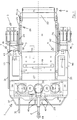
- Fig. 1 shows the top view of the U-shaped design of the towing device 1, which results from the two free legs 13 with the connecting leg 14.
- the free space 12 located inside the U is essentially filled by the platform 5, which is firmly connected to the legs 13, 14 and supports the defective wheel 11.
- the platform is approximately at the level of the lower edge of the surrounding legs 13, 14, so that the defective wheel 11 is already secured against slipping to the side and towards the front, the defective wheel 11 either towards the front abuts the fixed abutment surface 27, which is inserted obliquely at the front end of the platform 5 and is firmly connected to the surrounding legs 13, 14, or with the movable abutment surface 28, which, depending on the requirements of the damaged wheel 11 in various longitudinal positions on the platform 5 and can be attached.
- the free side of the U-shaped basic construction of the towing device 1 is closed by the removable slide 8.
- the slider 8 which can be moved in the direction of the platform 5 by means of the pulling device 9, the defective wheel 11 is rolled up or pushed up onto the platform 5, the towing device 1 in the region of the free edge 15 of the platform 5 as far as possible the subsurface 16 is lowered to facilitate this pushing up.
- an additional rim wedge is placed across the edge 15, which is dimensioned so that it fits into the rim well, so that the rim does not have to roll on its (usually no longer round) outer edges, but instead with the rim bed then on the rim wedge 99 placed therein, which is thicker than the height of the rim edges.
- the towing device 1 has four wheel units 3, one of which is located at the free end of the free leg 13 and two below the connecting leg 14.
- Each of the wheel units 3 consists of a plurality of rollers 41 arranged parallel to one another, the front wheel units 3 each having two parallel rollers 41 made of plastic or metal.
- the rear edge 15 of the platform 5 is lowered by means of an articulated connection of the rear wheel units 3 to the free ends of the free legs 13.
- the lifting cylinders 17 project obliquely from the front to the rear within the free legs 13.
- the pressurization and extension of the lifting cylinder 17 raises the axis 42 and thus also the platform 5 together with a possibly saddled defective wheel until the platform 5 is approximately horizontal, as in FIG. 2 shown.
- the towing device 1 is pulled together with the aircraft to be towed by means of the drawbar 2.
- the head piece of the drawbar 2 can be exchanged between a simple handle, which is only used to steer the towing device 1, and a towing eye 44, as shown in FIG. 1, for towing to a towing vehicle.
- a defective wheel 11 is pulled up onto the platform 5 by means of a longitudinal movement of the slide 8 against the platform 5.
- running elements 20 on the inside of each free leg 13 can be moved horizontally in the longitudinal direction in that each running element 20 has a roller 25 which runs in the interior of a corresponding C-profile 26, which is part of the free leg 13, as a guide 24.
- the slide 8 can be connected to these running elements 20, by means of aligned bores 45 in the lateral, parallel running, longitudinal legs 19 of the slide 8 and corresponding holes 45 in the barrel elements 20 bolts are inserted vertically and secured.
- aligned bores 45 in the lateral, parallel running, longitudinal legs 19 of the slide 8 and corresponding holes 45 in the barrel elements 20 bolts are inserted vertically and secured.
- the slide can be used in the position shown in FIG. 2, in which the inclined thrust plate 22, which is firmly connected to the lateral legs 19, presses against the defective wheel.
- the slider 8 can also be used rotated by 180 ° in the horizontal plane, so that the push roller 21 would then press against the defective wheel 11.
- the inclined position of the side legs 19 of the slider 8 relative to the running elements 20 can be determined by means of corresponding push-through bolts or other latching devices, as a result of which the height of the push roller 21 and the push plate 22 changes in order to lie approximately in the middle of the defective wheel.
- the slider 8 is completely removed or released from one of the free legs 13, and folded away around the other leg, around the then U-shaped towing device 1 with the free edge 15 of the platform 5 until in contact with the to be able to drive defective wheel 11 in the lowered state.
- the drawbar 2 is mounted in the center by means of a turntable 33 and on the other hand, the two front wheel units 3 by means of rotating rings 34, each of which has parallel, essentially vertical axes of rotation.
- each of the turntables 33, 34 has a horizontally lying gearwheel, an intermediate gearwheel 35 being intermeshed between the middle turntable 33 and the two outer turntables 34.
- a deflection of the drawbar 2 is thus implemented in an equally large and rectified deflection of the two front wheel units 3.
- a hydraulic pump 29 is accommodated, which is actuated by means of a rotation of the shaft 32 extending transversely to the longitudinal direction 10.
- the shaft 32 extends continuously on both sides of the drawbar 2, and has on both sides parallel to the longitudinal direction 10 projecting shoulder 36, on which one hand or both sides of the handle 31 can be attached to operate the pump 29.
- valves 30 on the pump which are adjusted by means of the hand levers 40, which also protrude towards the front and are in turn double, designed on both sides of the drawbar 2.
- the application of either the lifting cylinder 17 or the sliding cylinder 23 is selected, with at least the sliding cylinder 23 having to be a double-acting hydraulic cylinder which can be pressurized in both the retracting and the extending directions.
- Both the hand lever 40 and the connecting piece 36 are secured by a substantially horizontal, U-shaped protective bracket 37, which is arranged below the level of the lever 40 and to the front, i.e. in the direction of the drawbar 2, via the hand lever 40 and the extension piece 36 protrudes and is fixedly arranged at the front corners or the outer edges of the towing device 1.
- Hydraulic oil reservoirs 38 for supplying the hydraulic pump 29 are also arranged on both sides in the front connecting leg 14 in order to achieve a uniform weight distribution and a uniform movement of the cylinders.
- the unneeded hand sticks 31 are accommodated laterally on the outside in corresponding holders on the free legs 13, as shown in the upper half of FIG. 1.
- Both the connecting leg 14 and the free leg 13 of the towing device 1 are protected against moisture and, above all, damage from above by means of cover plates 39, which have an approximately hat-shaped cross-sectional contour.
Landscapes
- Engineering & Computer Science (AREA)
- Mechanical Engineering (AREA)
- Aviation & Aerospace Engineering (AREA)
- Health & Medical Sciences (AREA)
- Public Health (AREA)
- Transportation (AREA)
- Vehicle Cleaning, Maintenance, Repair, Refitting, And Outriggers (AREA)
- Handcart (AREA)
Description
Bei jedem Fahrzeug kann sich das Problem stellen, daß das Fahrzeug abgeschleppt werden muß, und wegen einer Beschädigung eines der Räder des Fahrzeuges ein Schleppen des Fahrzeuges auf eigenen Rädern nicht mehr möglich ist.The problem with any vehicle is that the vehicle has to be towed, and it is no longer possible to tow the vehicle on its own wheels because of damage to one of the wheels of the vehicle.
Dieses Problem ist bei Luftfahrzeugen mit ihren empfindlichen Fahrwerken gravierend. Besonders bei Militärflugzeugen mit ihren hohen Landegeschwindigkeiten und hohen Zuladungen kommt es bei Start und Landung häufig zu Reifenpannen. Einerseits soll beim Abschleppen eines von der Landebahn abgekommenen Flugzeuges mit defektem Fahrwerk eine zusätzliche Beschädigung des Rades oder Fahrwerkes während des Abschleppens aufgrund der hohen Kosten vermieden werden und andererseits soll in der Regel das Flugzeug möglichst schnell und zuverlässig auch unter erschwerten Bedingungen abgeschleppt werden, beispielsweise um die Start- und Landebahn wieder frei zu bekommen. Dies gilt besonders für Militärflugzeuge.This problem is serious for aircraft with their sensitive landing gear. In the case of military aircraft with their high landing speeds and high payloads, punctures often occur during take-off and landing. On the one hand, additional damage to the wheel or landing gear during towing should be avoided when towing an aircraft that has come off the runway with a defective landing gear due to the high costs, and on the other hand the aircraft should generally be towed as quickly and reliably as possible, even under difficult conditions, for example by to clear the runway again. This is especially true for military aircraft.
Aus der DE-U-79 25 944 ist bereits ein Abschleppgerät bekannt, bei dem das Bugrad eines Flugzeuges zwischen die Schenkel eines in der Aufsicht U-förmig gestelteten Abschleppgerätes auf eine tragende Plattform hinaufgezogen werden kann, indem die freie Hinterkante der Plattform auf den Boden abgesenkt werden kann. Dieses Abschleppgerät ist jedoch mehr zum Abschleppen eines Flugzeuges mit noch funktionierendem Bugrad als zum Bergen von Flugzeugen mit defektem Bugfahrwerk geeignet.From DE-U-79 25 944 a towing device is already known in which the nose wheel of an aircraft can be pulled up onto a supporting platform between the legs of a towing device designed in the form of a U in supervision by the free rear edge of the platform on the ground can be lowered. However, this towing device is more suitable for towing an aircraft with the nose wheel still functioning than for recovering aircraft with a defective nose gear.
Es ist daher die Aufgabe gemäß der Erfindung, ein möglichst autarkes, einfach zu bedienendes und einfach aufgebautes Abschlepp- und Bergegerät mit hoher Zuverlässigkeit zu schaffen, mit dem einzelne bzw. eng benachbarte Räder eines Fahrzeuges, die nicht mehr selbst fahrfähig sind, aufgenommen werden können und damit das gesamte Fahrzeug abgeschleppt werden kann.It is therefore the task according to the invention to create a self-sufficient, easy-to-use and simply constructed towing and recovery device with high reliability, with which individual or closely adjacent wheels of a vehicle that are no longer drivable are added can be and thus the entire vehicle can be towed.
Diese Aufgabe ist durch den kennzeichnenden Teil des Anspruchs 1 bzw. 2 gelöst. Vorteilhafte Ausführungsformen ergeben sich aus den Unteransprüchen.This object is solved by the characterizing part of
Durch die in der Aufsicht U-förmige Gestaltung des Abschleppgerätes mit einer tiefliegenden, tragenden Plattform im Freiraum der U-förmigen Gestaltung kann das defekte Rad, wenn es einmal auf der Plattform steht, aufgrund der drei gegenüber der Plattform erhöhten Schenkel, die die Plattform umgeben und zusammen die U-förmige Gestalt bilden, nicht mehr von der Plattform unabsichtlich abrutschen. Lediglich auf der vierten Seite ist eine Sicherung gegen das Herabrutschen des defekten Rades vorzusehen.Due to the U-shaped design of the towing device with a low-lying, load-bearing platform in the free space of the U-shaped design, the defective wheel, once it is standing on the platform, can be raised due to the three legs raised opposite the platform, which surround the platform and together form the U-shaped shape, no longer of the Slipping the platform unintentionally. Only on the fourth side is a safeguard against the defective wheel slipping down.
Durch die Anordnung je einer Radeinheit am freien Ende jedes freien Schenkels sowie an den Ecken des verbindenedn Schenkels des Abschleppgerätes wird die Standsicherheit des Abschleppgerätes erhöht.The stability of the towing device is increased by arranging one wheel unit at the free end of each free leg and at the corners of the connected leg of the towing device.
Mittels der Absenkeinrichtung kann die freie Kante der Plattform gegenüber den Radeinheiten an den freien Schenkeln bis auf den Untergrund abgesenkt werden. Das erleichtert einerseits das Hinauffahren oder Hinaufschieben des defekten Rades auf die Plattform und ermöglicht andererseits bei aufgesatteltem, defekten Rad ein Abbremsen des Abschleppgerätes, z. B. in abschüssigem Gelände, indem die Plattform bis auf den Untergrund abgelassen wird und eine hohe Reibung zwischen Plattform und Untergrund entsteht.By means of the lowering device, the free edge of the platform can be lowered to the ground in relation to the wheel units on the free legs. On the one hand, this makes it easier to drive up or push the defective wheel onto the platform and, on the other hand, it enables the towing device, e.g. B. in sloping terrain by lowering the platform down to the ground and creating a high level of friction between the platform and the ground.
Indem ein zwischen den Enden der freien Schenkel vorgesehener Schieber leicht entfernbar ist, kann das Abschleppgerät bei entferntem Schieber mit der offenen Seite seiner U-förmigen Gestaltung, also der freien Kante der Plattform, im abgesenkten Zustand bis unmittelbar an das beschädigte Rad herangefahren werden.Since a slide provided between the ends of the free legs can be easily removed, the towing device can be moved up to the damaged wheel with the open side of its U-shaped design, i.e. the free edge of the platform, in the lowered state when the slide is removed.
Anschließend wird - auf der von der Plattform abgewandten Seite des defekten Rades - der Schieber zwischen die freien Enden des Abschleppgerätes eingesetzt und entlang der freien Schenkel in Richtung auf die Plattform mittels einer Zugeinrichtung bewegt, wodurch das defekte Rad auf die tragende Plattform hinaufgeschoben wird.Then - on the side of the defective wheel facing away from the platform - the slider is inserted between the free ends of the towing device and moved along the free legs in the direction of the platform by means of a pulling device, as a result of which the defective wheel is pushed up onto the supporting platform.
Das aufgesattelte Rad bleibt bezüglich der vorher freien Seite des U-förmigen Abschleppgerätes durch den Schieber gegen Herabrutschen oder Herabfahren gesichert. Dieser muß sich in einer ausreichenden Höhe über der tragenden Plattform befinden, ebenso wie auch die drei die Plattform umgebenden Schenkel der U-förmigen Gestaltung eine ausreichende maximale Höhe zur Absicherung des defekten Rades besitzen müssen.The saddled wheel remains secured against slipping or descending with respect to the previously free side of the U-shaped towing device by the slide. This must be at a sufficient height above the supporting platform, as must the three legs of the U-shaped section surrounding the platform Design must have a sufficient maximum height to protect the defective wheel.
Bei aufgesatteltem defektem Rad wird das Abschleppgerät mittels einer Deichsel gezogen, wobei im vorderen, verbindenden Schenkel des Abschleppgerätes zwei lenkbare Radeinheiten untergebracht sind.When the defective wheel is saddled, the towing device is pulled by means of a drawbar, two steerable wheel units being accommodated in the front connecting leg of the towing device.
Vorzugsweise sind diese Radeinheiten nicht frei drehbar gelagert, sondern ihre Lenkung erfolgt in Abhängigkeit vom Lenkeinschlag der Deichsel. Dies geschieht vorzugsweise dadurch, daß sowohl die Deichsel als auch die vorderen Radeinheiten mittels Drehkränzen mit im wesentlichen senkrechten Drehachsen im Abschleppgerät gelagert sind und die Drehkränze der vorderen Radeinheiten mit dem Drehkranz der Deichsel über ein Zwischenzahnrad miteinander verbunden sind, so daß sie bei Auslenken der Deichsel gleichwirkend ausgelenkt werden.These wheel units are preferably not freely rotatable, but are steered as a function of the steering angle of the drawbar. This is preferably done in that both the drawbar and the front wheel units are mounted in the towing device by means of turntables with substantially vertical axes of rotation and the turntables of the front wheel units are connected to the turntable of the drawbar via an intermediate gear so that they deflect when the drawbar is deflected be deflected in the same way.
Die Radeinheiten bestehen dabei vorzugsweise aus mehreren nebeneinander angeordneten, massiven Kunststoffrollen, um eine große Auflagefläche zu erhalten. Aufgrund der geringen Bewegungsgeschwindigkeiten des Abschleppgerätes sind Rollen aus massivem Material ausreichend.The wheel units preferably consist of several solid plastic rollers arranged next to one another in order to obtain a large contact surface. Due to the low speed of movement of the towing device, rollers made of solid material are sufficient.
Das Bergen eines Luftfahrtgerätes geht wie folgt vor sich:The recovery of an aircraft takes place as follows:
Zunächst wird - bei einem bis ans äußerste Ende der freien Schenkel verfahrenen Schieber - der Schieber entfernt und das nun offene, U-förmige Abschleppgerät mit seiner offenen Seite an das defekte Rad bzw. Fahrwerk des Flugzeuges herangefahren.First, with a slider moved to the extreme end of the free leg, the slider is removed and the open, U-shaped towing device is moved with its open side towards the defective wheel or landing gear of the aircraft.
Dann wird die freie Kante der tragenden Plattform des Abschleppgerätes bis auf den Untergrund abgelassen und das Abschleppgerät bis auf Anlage an bzw. unter das defekte Rad herangefahren. Der Schieber wird nun hinter dem defekten Rad, also auf der von der tragenden Plattform abgewandten Seite des defekten Rades, zwischen den freien Schenkeln befestigt und mittels der Zugeinrichtung in Richtung auf die Plattform herangezogen, wobei der Schieber das defekte Rad auf die Plattform hinaufschiebt.Then the free edge of the supporting platform of the towing device is lowered to the ground and the towing device is brought up to the system on or under the defective wheel. The slide is now fastened behind the defective wheel, that is to say on the side of the defective wheel facing away from the supporting platform, between the free legs and by means of the pulling device in the direction of the platform The slider pushes the defective wheel up onto the platform.
Dabei kann der Schieber entweder mit der Schubrolle oder dem schräg aufragenden, festen Schubschild gegen das Rad drücken. Das Schubschild wird dabei eingesetzt, wenn der Gummi des Rades fest am Boden angeklebt ist. Dieser Gummi wird dann vom Schubschild wie von einem Messer vom Boden abgeschnitten.The slider can either push the push roller or the diagonally rising, fixed push plate against the wheel. The push plate is used when the rubber of the wheel is firmly glued to the floor. This rubber is then cut off the floor by the thrust shield like a knife.
Anschließend wird die Plattform mit dem daraufstehenden defekten Rad angehoben, um eine ausreichende Bodenfreiheit zum Fahren und Lenken des Abschleppgerätes zu gewinnen. Nur für die oben beschriebenen Notbremsungen wird die Plattform erneut bis auf den Untergrund herabgelassen.Then the platform with the defective wheel on it is raised in order to gain sufficient ground clearance for driving and steering the towing device. The platform is lowered again only to the ground for the emergency braking operations described above.
Anstelle eines vollständigen Entfernen des Schiebers kann dieser auch nur in Verbindung mit einem der freien Schenkel gelöst und am anderen freien Schenkel verschwenkt werden, um einen freien Zugang des defekten Rades zur Plattform zu ermöglichen.Instead of completely removing the slide, it can also be loosened only in connection with one of the free legs and pivoted on the other free leg to allow free access of the defective wheel to the platform.
Falls es sich bei dem defekten Rad um ein Bugfahrwerk eines Flugzeuges handelt, wird die Deichsel des Abschleppgerätes durch die spezielle Schleppstange dieses Flugzeugtypes ersetzt und direkt mit einem Zugfahrzeug verbunden, welches mittels des Abschleppgerätes das gesamte Flugzeug zieht.If the defective wheel is the nose gear of an aircraft, the tiller of the towing device is replaced by the special towing bar of this type of aircraft and connected directly to a towing vehicle that pulls the entire aircraft using the towing device.
Handelt es sich bei dem defekten Fahrwerk um eines der Hauptfahrwerke, die sich in der Regel unter den Flügeln des Flugzeuges befinden, so wird am Bugfahrwerk in üblicher Weise mittels der Schleppstange ein Zugfahrzeug angehängt und das Flugzeug geschleppt, während das unter dem defekten Hauptfahrwerk angeordnete Abschleppgerät mittels der Deichsel lediglich von Hand in die gewünschte Richtung gelenkt wird.If the defective landing gear is one of the main landing gears, which are usually located under the wings of the aircraft, then a towing vehicle is attached to the nose landing gear in the usual way by means of the towing bar and the aircraft is towed, while the towing device arranged under the defective main landing gear is only steered by hand in the desired direction.
Das Betätigen der Zugeinrichtung sowie der Absenkvorrichtung erfolgt vorzugsweise hydraulisch, wobei wenigstens eine im Abschleppgerät angeordnete hydraulische Pumpe mittels Handschwengel betätigt wird. Auch die entsprechenden Ventilstellungen werden von Hand eingestellt.The pulling device and the lowering device are preferably actuated hydraulically, at least one hydraulic pump arranged in the towing device being actuated by means of a hand-held handle. The corresponding valve positions are also set by hand.
Dadurch ist für das Bergen eines Luftfahrzeuges jedes beliebige Zugfahrzeug geeignet, ohne daß an diesem Zugfahrzeug spezielle Hydraulikanschlüsse, Druckluftanschlüsse oder ähnliches zur Energieversorgung des Abschleppgerätes vorhanden sein müssen.As a result, any towing vehicle is suitable for the rescue of an aircraft without special hydraulic connections, compressed air connections or the like having to be present on this towing vehicle for supplying energy to the towing device.
Die tragende Plattform des Abschleppgerätes wird abgesenkt und gehoben mittels je eines in den freien Schenkeln angeordneten hydraulischen Zylinders, der schräg nach oben ragt und auf einen Hebel einwirkt, der einerseits mit einer der Radeinheiten am freien Schenkel und andererseits mit dem freien Schenkel schwenkbar verbunden ist.The supporting platform of the towing device is lowered and raised by means of a hydraulic cylinder arranged in each of the free legs, which projects obliquely upwards and acts on a lever which is pivotally connected to one of the wheel units on the free leg and on the other hand to the free leg.
Durch Betätigen des Hydraulikzylinders werden die freien Schenkel des Abschleppgerätes und damit auch die freie Kante dessen tragender Plattform gegenüber den Radeinheiten an den freien Schenkeln abgesenkt.By actuating the hydraulic cylinder, the free legs of the towing device and thus also the free edge of its supporting platform are lowered relative to the wheel units on the free legs.
Der Schieber ist an den freien Schenkeln mittels Laufelementen beidseits befestigt, die vorzugsweise wenigstens je eine Rolle aufweisen, die in einem zum Innenraum des Abschleppgerätes offenen, in Längsrichtung der freien Schenkel verlaufenden C-Profil geführt sind.The slide is fastened on both sides to the free legs by means of running elements, which preferably each have at least one roller each, which are guided in a C-profile which is open to the interior of the towing device and runs in the longitudinal direction of the free legs.
An diesen Laufelementen kann der Schieber mittels zweier paralleler, seitlicher Schenkel in verschiedenen Positionen in Längsrichtung des Abschleppgerätes befestigt werden. Dies geschieht am einfachsten mittels Steckbolzen, die durch eine von mehreren - sowohl in den Schenkeln als auch in den Laufelementen - vorhandenen, fluchtenden Bohrungen eingesteckt werden können.The slide can be fastened to these running elements in two positions in the longitudinal direction of the towing device by means of two parallel, lateral legs. The easiest way to do this is by means of plug-in bolts which can be inserted through one of several aligned bores - both in the legs and in the running elements.
Eine andere Lösung besteht darin, den Schieber an einem der Laufelemente drehbar um eine im wesentlichen senkrechte oder parallel zur Längsrichtung des Abschleppgerätes waagerechte Schwenkachse zu befestigen, und lediglich die Verbindung zum anderen Laufelement entfernbar zu gestalten.Another solution is to fasten the slide on one of the running elements about a pivot axis which is essentially vertical or horizontal parallel to the longitudinal direction of the towing device, and only to make the connection to the other running element removable.
Dadurch muß nur eine Verbindung zum Öffnen des Abschleppgerätes gelöst und dann der Schieber lediglich in die geöffnete Position geschwenkt werden. Bei starken Beschädigungen am Fahrwerk kann der in der geöffneten Stellung dann noch mit dem Abschleppgerät verbundene Schieber jedoch gerade zu Behinderungen oder Beschädigungen bei der Bergung führen.As a result, only one connection to open the towing device must be released and then the slide only in the open position can be pivoted. In the event of severe damage to the undercarriage, the slide which is still connected to the towing device in the open position can lead to disabilities or damage during recovery.
Das Wesentliche am Schieber ist ein quer zur Längsrichtung des Abschleppgerätes angeordnetes, das defekte Rad schiebendes Element. Dabei sind parallel zueinander sowohl eine drehbar gegenüber den seitlichen Schenkeln gelagerte Schubrolle als auch ein fest mit den Schenkeln verbundener Schubschild vorhanden. Der Schieber selbst kann dabei zumindest in der vollständig entfernbaren Version wahlweise so eingesetzt werden, daß entweder die Schubrolle oder der Schubschild gegen das defekte Rad gerichtet sind, je nach dem, welches der beiden Elemente besser für die momentane Bergungssituation geeignet ist.The essence of the slide is an element that is arranged transversely to the longitudinal direction of the towing device and pushes the defective wheel. Both a thrust roller rotatably mounted with respect to the side legs and a thrust plate fixedly connected to the legs are present parallel to each other. The slide itself can be used at least in the completely removable version so that either the push roller or the push plate are directed against the defective wheel, depending on which of the two elements is better suited for the current salvage situation.
Falls das defekte Rad sich noch drehen kann und nicht allzu unrund ist, wird vorzugsweise die Schubrolle eingesetzt, um ein weniger reibungsintensives Abrollen der Schubrolle am ebenfalls während des Aufsattelns drehenden, defekten Rad zu ermöglichen.If the defective wheel can still turn and is not too out of round, the pushing roller is preferably used in order to enable the pushing roller to roll on the defective wheel, which is also rotating during the saddling process, with less friction.
Ist dagegen das defekte Fahrwerk soweit geschädigt, daß das defekte Rad nur noch ohne Drehung auf die Plattform hinaufgeschoben werden kann, so wird der nicht drehende Schubschild eingesetzt werden, da in diesem Fall die drehbare Schubrolle die Gefahr in sich birgt, daß das nicht mehr drehende, defekte Rad über die drehbare Schubrolle wegspringt. Zusätzlich schabt der Schubschild knapp über dem Boden und schneidet dadurch die am Boden haftenden Gummireste ab.If, on the other hand, the defective undercarriage is damaged to such an extent that the defective wheel can only be pushed up onto the platform without rotation, the non-rotating push plate will be used, since in this case the rotating push roller carries the risk that the non-rotating one , defective wheel jumps over the rotating push roller. In addition, the push shield scrapes just above the floor, thereby cutting off the rubber residue adhering to the floor.
Die tragende Plattform weist an ihrem von der freien Kante gegenüberliegenden Ende eine quer zur Längsrichtung des Abschleppgerätes verlaufende feste Anschlagfläche auf, um beim Hinaufschieben des defekten Rades dieses Rad fest bis in Anlage an die feste Anschlagfläche zu drücken. Zusätzlich ist eine entfernbare, schräg gestellte Anschlagfläche vorhanden, die in verschiedenen Längspositionen auf der Plattform befestigbar ist, um ein defektes Rad aus Gründen der Gewichtsverteilung, der unterschiedlichen Raddurchmesser etc. an einer bestimmten Längsposition auf der Plattform zu halten.At its end opposite the free edge, the supporting platform has a fixed stop surface running transversely to the longitudinal direction of the towing device, in order to press this wheel firmly against the fixed stop surface when the defective wheel is pushed up. In addition, there is a removable, inclined stop surface which can be fastened in various longitudinal positions on the platform in order to avoid a defective wheel due to the weight distribution to keep different wheel diameters etc. at a certain longitudinal position on the platform.
Die Schubeinrichtung umfaßt in jedem der freien Schenkel wenigstens einen hydraulischen Schiebezylinder, der in Längsrichtung der freien Schenkel angeordnet ist und die Laufelemente, an denen der Schieber befestigt ist, entlang der freien Schenkel bewegt.The pushing device comprises in each of the free legs at least one hydraulic sliding cylinder which is arranged in the longitudinal direction of the free legs and moves the running elements to which the slide is fastened along the free legs.
Im verbindenden Schenkel des Abschleppgerätes ist wenigstens eine hydraulische Pumpe sowie wenigstens ein Tank für Hydraulikflüssigkeit angeordnet. Die hydraulische Pumpe wird mittels eines Handschwengels betätigt, wobei wahlweise zusätzlich externe Hydraulikanschlüsse vorhanden sein können.At least one hydraulic pump and at least one tank for hydraulic fluid are arranged in the connecting leg of the towing device. The hydraulic pump is operated by means of a hand lever, with additional hydraulic connections optionally being available.
Die Handschwengel wirken über eine drehbare Welle auf die Hydraulikpumpe ein, wobei sich diese Welle quer zur Längsrichtung in oder an dem verbindenden Schenkel befindet.The hand sticks act on the hydraulic pump via a rotatable shaft, this shaft being located transversely to the longitudinal direction in or on the connecting leg.
Dabei ragen beidseits der Deichsel Ansatzstutzen nach vorne, also etwa parallel zur Deichsel, von der Welle ab, um das Aufschieben eines Handschwengels auf die Ansatzstutzen an derjenigen Seite zu ermöglichen, an der die beste Zugänglichkeit am Abschleppgerät unter dem zu bergenden Flugzeug möglich ist.Approach sockets protrude from the shaft on both sides of the drawbar, i.e. roughly parallel to the drawbar, in order to enable a hand lever to be pushed onto the connection sockets on the side where the best accessibility to the towing device is possible under the aircraft to be recovered.
Ebenfalls von dem verbindenden Schenkel nach vorne ragen Stellhebel zum Umstellen der Ventile hervor, mit deren Hilfe der an der Hydraulikpumpe aufgebrachte Druck wechselweise an die Hubzylinder oder die Schiebezylinder geleitet wird, und - bei doppelt wirkenden Zylindern, wie sie wenigstens beim Schiebezylinder notwendig sind - dort wiederum die Einleitung in eine der beiden Kammern dieser Zylinder.Also protruding from the connecting leg to the front are control levers for changing over the valves, with the aid of which the pressure applied to the hydraulic pump is alternately directed to the lifting cylinder or the sliding cylinder, and - in the case of double-acting cylinders, as is necessary at least for the sliding cylinder - there again the introduction into one of the two chambers of these cylinders.
Um die mechanischen Teile, die aus der Vorderseite des verbindenden Schenkels des Abschleppgerätes hervorragen, zu schützen, läuft im Abstand vor der Vorderkante des verbindenden Schenkels des Abschleppgerätes im Abstand ein Schutzbügel um, der an den Seiten des Abschleppgerätes befestigt ist, und eine Beschädigung sowohl der Ansatzstutzen für den Handschwengel als auch der Betätigungshebel für die Ventile zu verhindern.In order to protect the mechanical parts that protrude from the front of the connecting leg of the towing device, a protective bracket, which is fastened to the sides of the towing device, runs around the front edge of the connecting leg of the towing device and one To prevent damage to both the connecting piece for the hand handle and the actuating lever for the valves.
An der Deichsel ist das freie Ende auswechselbar, wobei dort zwischen einer Querstange zum Lenken per Hand und einer Anhängeöse zum Anhängen des Abschleppgerätes an die üblichen Anhängekupplungen von Fahrzeugen gewählt werden kann.The free end of the drawbar can be replaced, and there is a choice between a crossbar for manual steering and a towing eye for attaching the towing device to the usual towbars of vehicles.
Damit steht ein Abschleppgerät zur Verfügung, welches aufgrund seines einfachen Aufbaus und weniger, einfacher Bedienungselemente einfach herzustellen und leicht zu bedienen ist. Zusätzlich kann dieses Abschleppgerät aufgrund seiner geringen Abmessungen von etwa 2 m Länge und 1,30 m Breite bei nur etwa 45 cm Höhe (ohne Deichsel) und einem Gewicht von nur etwa 700 kg leicht transportiert werden.This means that a towing device is available which, due to its simple structure and fewer, simpler operating elements, is easy to manufacture and easy to use. In addition, this towing device can be easily transported due to its small dimensions of about 2 m in length and 1.30 m in width at only about 45 cm in height (without drawbar) and a weight of only about 700 kg.
Eine Ausführungsform gemäß der Erfindung ist im folgenden anhand der Figuren beispielhaft näher beschrieben. Es zeigen
- Fig. 1
- eine Aufsicht auf das Abschleppgerät und
- Fig. 2
- eine Seitenansicht des Abschleppgerätes.
- Fig. 1
- a supervision of the towing device and
- Fig. 2
- a side view of the towing device.
Fig. 1 zeigt in der Aufsicht die U-förmige Gestaltung des Abschleppgerätes 1, die sich aus den beiden freien Schenkeln 13 mit dem verbindenden Schenkel 14 ergibt. Der im Inneren des U befindliche Freiraum 12 wird in der Aufsicht im wesentlichen durch die fest mit den Schenkeln 13, 14 verbundene, das defekte Rad 11 tragende Plattform 5 ausgefüllt.Fig. 1 shows the top view of the U-shaped design of the
Wie Fig. 2 zeigt, liegt die Plattform in etwa auf der Höhe der Unterkante der umgebenden Schenkel 13, 14, so daß das defekte Rad 11 zur Seite und nach vorne hin bereits gegen ein Verrutschen gesichert ist, wobei das defekte Rad 11 nach vorne entweder an der festen Anschlagfläche 27 anliegt, die am vorderen Ende der Plattform 5 schräg eingesetzt und mit den umgebenden Schenkeln 13, 14 fest verbunden ist, oder mit der beweglichen Anschlagfläche 28, die je nach Erfordernis des beschädigten Rades 11 in verschiedenen Längspositionen auf der Plattform 5 aufgesteckt und befestigt werden kann.As shown in Fig. 2, the platform is approximately at the level of the lower edge of the surrounding
Die freie Seite der U-förmigen Grundkonstruktion des Abschleppgerätes 1 wird durch den entfernbaren Schieber 8 geschlossen. Mit Hilfe des Schiebers 8, der in Richtung auf die Plattform 5 mittels der Zugeinrichtung 9 bewegt werden kann, wird das defekte Rad 11 auf die Plattform 5 hinaufgerollt oder hinaufgeschoben, wobei das Abschleppgerät 1 im Bereich der freien Kante 15 der Plattform 5 möglichst bis auf den Untergrund 16 abgesenkt wird, um dieses Hinaufschieben zu erleichtern.The free side of the U-shaped basic construction of the
Falls der Radgummi nicht mehr vorhanden ist, wird zusätzlich ein Felgenkeil quer über die Kante 15 gelegt, der so dimensioniert ist, daß er in das Felgenbett paßt, sodaß die Felge nicht auf ihren (in der Regel nicht mehr runden) Aussenrändern rollen muß, sondern mit dem Felgenbett dann auf dem darin plazierten Felgenkeil 99, der dicker ist als die Höhe der Felgenränder.If the wheel rubber is no longer available, an additional rim wedge is placed across the
Das Abschleppgerät 1 besitzt vier Radeinheiten 3, von denen sich je eine am freien Ende der freien Schenkel 13 und zwei unter dem verbindenden Schenkel 14 befinden. Jede der Radeinheiten 3 besteht aus mehreren, parallel zueinander angeordneten Rollen 41, wobei die vorderen Radeinheiten 3 jeweils zwei parallele Rollen 41 aus Kunststoff oder Metall aufweisen.The towing
Das Absenken der Hinterkante 15 der Plattform 5 geschieht mittels einer gelenkigen Verbindung der hinteren Radeinheiten 3 mit den freien Enden der freien Schenkel 13.The
Zu diesem Zweck sind an jedem freien Ende eines freien Schenkels 13 zwei parallele, aus Flachmaterial erstellte, doppelarmige Hebel 18 über eine mittlere Achse 42 gelenkig mit dem jeweiligen freien Schenkel 13 verbunden. An dem über das freie Ende der freien Schenkel 13 hinausragenden Ende des Doppelhebels 18 sind die Radeinheiten 3 befestigt, während am Ende des anderen Hebelarmes über eine Achse 43 jeweils ein Hubzylinder 17 angreift, der am freien Schenkel 13 befestigt ist und dessen Wirkrichtung im Winkel zu dem ihm zugeordneten Hebelarm des Doppelhebels 18 steht.For this purpose, at each free end of a
Wie Fig. 2 zeigt, stehen die Hubzylinder 17 von vorne nach hinten schräg aufragend innerhalb der freien Schenkel 13.As shown in FIG. 2, the lifting
Bei einem Einfahren der Hubzylinder 17 senkt sich die mittlere Achse 42 und damit das freie Ende der Schenkel 13 gegenüber den hinteren Radeinheiten 3 ab, bis die Hinterkante 15 der Plattform 5 den Untergrund 16 erreicht. Das Einfahren des Hubzylinders 17 ist aufgrund des Eigengewichtes des Abschleppgerätes 1 sowie eines eventuell auf der Plattform 5 sitzenden defekten Fahrwerkes bereits durch Öffnen der Hydraulikzufuhr des Hubzylinders 17 möglich, so daß dieser nicht unbedingt als doppelt wirkender Hydraulikzylinder ausgebildet sein muß.When the lifting
Das Druckbeaufschlagen und Ausfahren des Hubzylinders 17 hebt die Achse 42 und damit auch die Plattform 5 zusammen mit einem eventuell aufgesattelten defekten Rad an, bis die Plattform 5 in etwa waagerecht steht, wie in FIg. 2 dargestellt.The pressurization and extension of the lifting
In dieser Position wird das Abschleppgerät 1 zusammen mit dem abzuschleppenden Flugzeug mittels der Deichsel 2 gezogen. Das Kopfstück der Deichsel 2 ist auswechselbar zwischen einem einfachen Handgriff, der lediglich zum Lenken des Abschleppgerätes 1 dient und einer Anhängeöse 44, wie sie in Fig. 1 dargestellt ist, zum Anhängen an ein Schleppfahrzeug.In this position, the towing
Das Heraufziehen eines defekten Rades 11 auf die Plattform 5 geschieht mittels einer Längsbewegung des Schiebers 8 gegen die Plattform 5. Zu diesem Zweck sind Laufelemente 20 auf den Innenseiten jedes freien Schenkels 13 in der Waagerechten in Längsrichtung verfahrbar, indem jedes Laufelement 20 eine Rolle 25 aufweist, die im Innenraum eines entsprechenden C-Profiles 26, welches Teil des freien Schenkels 13 ist, als Führung 24 entlangläuft.A defective wheel 11 is pulled up onto the
Mit diesen Laufelementen 20 kann der Schieber 8 verbunden werden, indem durch fluchtende Bohrungen 45 in den seitlichen, parallel laufenden, in Längsrichtung liegenden Schenkeln 19 des Schiebers 8 und entsprechenden Bohrungen 45 in den Laufelementen 20 Bolzen senkrecht hindurchgesteckt und gesichert werden. Durch unterschiedliche Axialpositionen kann bereits eine grobe Anpassung an den Durchmesser des beschädigten Rades 11 erfolgen, um auf hydraulischem Wege keine allzu großen Verschiebewege des Schiebers 8 bewältigen zu müssen.The
Zusätzlich kann der Schieber in der in Fig. 2 dargestellten Position eingesetzt werden, in der der schräg gestellte, fest mit den seitlichen Schenkeln 19 verbundene Schubschild 22 gegen das defekte Rad drückt.In addition, the slide can be used in the position shown in FIG. 2, in which the
Der Schieber 8 kann jedoch in der waagerechten Ebene auch um 180° gedreht eingesetzt werden, so daß dann die Schubrolle 21 gegen das defekte Rad 11 drücken würde.However, the
Zusätzlich kann über entsprechende Durchsteckbolzen oder andere Rasteinrichtungen die Schrägstellung der seitlichen Schenkel 19 des Schiebers 8 gegenüber den Laufelementen 20 bestimmt werden, wodurch sich die Höhenlage der Schubrolle 21 und des Schubschildes 22 verändert, um möglichst etwa in der Mitte des defekten Rades anzuliegen.In addition, the inclined position of the
Zur Aufnahme des defekten Rades 11 wird der Schieber 8 vollständig entfernt oder von einem der freien Schenkel 13 gelöst, und um den anderen Schenkel herum weggeklappt, um das dann U-förmige Abschleppgerät 1 mit der freien Kante 15 der Plattform 5 bis in Anlage an das defekte Rad 11 im abgesenkten Zustand heranfahren zu können.To accommodate the defective wheel 11, the
Anschließend wird der Schieber 8 hinter dem Rad 11 wieder mit beiden freien Schenkeln 13 verbunden und die hydraulischen Schiebezylinder 23, die in den freien Schenkeln 13 in Längsrichtung angeordnet sind, bewegen die Laufelemente 20 auf die Plattform 5 zu, und damit auch den Schieber 8.Subsequently, the
Im verbindenden Schenkel des Abschleppgerätes 1 sind zum einen mittig die Deichsel 2 mittels eines Drehkranzes 33 gelagert und zum anderen die beiden vorderen Radeinheiten 3 mittels Drehkränzen 34, die jeweils parallele, im wesentlichen senkrechte Drehachsen besitzen.In the connecting leg of the
Um einen Lenkeinschlag der Deichsel 2 gleichwirkend auf die vorderen Radeinheiten 3 zu übertragen, besitzt jeder der Drehkränze 33, 34 ein waagerecht liegendes Zahnrad, wobei zwischen dem mittleren Drehkranz 33 und den beiden außen liegenden Drehkränzen 34 je ein Zwischenzahnrad 35 kämmend eingesetzt ist. Eine Auslenkung der Deichsel 2 wird damit in eine gleich große und gleichgerichtete Auslenkung der beiden vorderen Radeinheiten 3 umgesetzt.In order to transfer a steering angle of the
Zusätzlich ist im vorderen, verbindenden Schenkel 14 des Abschleppgerätes 1 eine hydraulische Pumpe 29 untergebracht, die mittels einer Drehung der quer zur Längsrichtung 10 verlaufenden Welle 32 betätigt wird. Die Welle 32 erstreckt sich durchgehend beidseits der Deichsel 2, und besitzt auf beiden Seiten parallel zur Längsrichtung 10 nach vorne abragende Ansatzstutzen 36, auf welche wahlweise einseitig oder auch beidseitig Handschwengel 31 aufgesteckt werden können, um die Pumpe 29 zu betätigen.In addition, in the front, connecting
An der Pumpe befinden sich Ventile 30, die mittels der ebenfalls nach vorne abragenden und wiederum doppelt, beidseits der Deichsel 2 ausgebildeten, Handhebel 40 verstellt werden. Mit Hilfe der Ventile 30 wird die Beaufschlagung wahlweise der Hubzylinder 17 oder der Schiebezylinder 23 gewählt, wobei mindestens der Schiebezylinder 23 ein doppelt wirkender Hydraulikzylinder sein muß, der sowohl in Einfahr- als auch in Ausfahrrichtung mit Druck beaufschlagbar ist.There are valves 30 on the pump, which are adjusted by means of the hand levers 40, which also protrude towards the front and are in turn double, designed on both sides of the
Sowohl die Handhebel 40 als auch die Ansatzstutzen 36 werden durch einen im wesentlichen in der Waagerechten liegenden, U-förmigen Schutzbügel 37 gesichert, der unterhalb der Ebene der Hebel 40 angeordnet ist und nach vorne, also in Richtung der Deichsel 2, über die Handhebel 40 und die Ansatzstutzen 36 hinausragt und an den vorderen Ecken oder den Außenkanten des Abschleppgerätes 1 fest angeordnet ist.Both the
Im vorderen, verbindenden Schenkel 14 sind ferner beidseits Hydrauliköl-Behälter 38 zur Versorgung der hydraulischen Pumpe 29 angeordnet, um eine gleichmäßige Gewichtsverteilung und eine gleichmäßigeBewegung der Zylinder zu erreichen.
Während des Verfahrens des Abschleppgerätes 1 werden die nicht benötigten Handschwengel 31 seitlich außen in entsprechenden Halterungen an den freien Schenkeln 13 untergebracht, wie in der oberen Bildhälfte der Fig. 1 dargestellt.During the movement of the
Sowohl der verbindende Schenkel 14 als auch die freien Schenkel 13 des Abschlepgerätes 1 sind mittels Abdeckblechen 39, die eine etwa hutförmige Querschnittskontur besitzen, gegen Näße und vor allem Beschädigungen von oben geschützt.Both the connecting
Claims (16)
- A towing apparatus (1) for vehicles with a defective wheel, in particular for aircraft, comprising- a towbar (2) for moving the towing apparatus (1),- at least three wheel units of which at least one wheel unit is steerable,- a configuration of the towing apparatus (1), which is U-shaped in plan view, with a platform (5) for carrying the defective wheel (11), in the free space (12) of the U-shaped towing apparatus,- a wheel unit (3) at each free limb (13) of the U-shaped towing apparatus (1), wherein- a rear free edge (15) of the platform (5) can be lowered on to the ground (16),characterised in thata) the lowering means (7) of the platform (5) is hydraulically actuable,b) a slider (8) is removably inserted between the free limbs (13) of the U-shaped towing apparatus (1), by the slider being fixed with respect to the free limbs (13) by means of cotter pins, andc) a pulling means (9) can move the inserted slider (8) in the longitudinal direction along the U-shaped towing apparatus (1).
- A towing apparatus (1) for vehicles with a defective wheel, in particular for aircraft, comprising- a towbar (2) for moving the towing apparatus (1),- at least three wheel units of which at least one wheel unit is steerable,- a configuration of the towing apparatus (1), which is U-shaped in plan view, with a platform (5) for carrying the defective wheel (11), in the free space (12) of the U-shaped towing apparatus,- a wheel unit (3) at each free limb (13) of the U-shaped towing apparatus (1), wherein- a rear free edge (15) of the platform (5) can be lowered on to the ground (16),characterised in thata) the lowering means (7) of the platform (5) is hydraulically actuable,b) a slider (8) is removably inserted in a simple manner between the free limbs (13) of the U-shaped towing apparatus (1) by the slider (8) being fixed with respect to the one free limb (13) about a pivot axis which is substantially perpendicular or horizontal in parallel relationship to the longitudinal direction of the towing apparatus and the connection of the slider (8) to the other free limb (13) being adapted to be removable, andc) a pulling means (9) can move the inserted slider (8) in the longitudinal direction along the U-shaped towing apparatus (1).
- A towing apparatus according to claim 1 characterised in that the towbar is easily removable and can be replaced by the specific towing bar of a type of vehicle.
- A towing apparatus according to claim 1 or claim 2 characterised in that a towbar (2) and two wheel units (3) which are steered by the towbar (2) are arranged in the connecting limb (14) of the U-shaped towing apparatus (1).
- A towing apparatus according to one of the preceding claims characterised in that the lowering means (7) includes in each of the free limbs (13) respective hydraulic stroke cylinders (17) which are arranged to project inclinedly upwardly and which by way of a respective two-armed lever (18) pivot the wheel units (3) arranged on the free limbs (13) relative to the towing apparatus (1) in their position in respect of height.
- A towing apparatus according to one of the preceding claims characterised in that the slider (8) has two parallel lateral limbs (19) which can be fixed in different positions in the longitudinal direction (10) on runner elements (20) which are movable along the free limbs (13) and the slider (8) has between the lateral limbs (19) in succession in the longitudinal direction a rotatably mounted thrust roller (21) and a thrust plate (22).
- A towing apparatus according to claim 6 characterised in that the slider (8) can be fixed to the runner elements (20) with the thrust roller (21) or the thrust plate (22) towards the towbar.
- A towing apparatus according to one of the preceding claims characterised in that the runner elements (20) are horizontally displaceable along longitudinally directed guides (24) of the free limbs (13) by means of at least one respective thrust cylinder (23).
- A towing apparatus according to claim 8 characterised in that each runner element (20) includes at least one roller (25) which runs in a C-shaped member (26), which is open towards the free space (12), on the free limb (13).
- A towing apparatus according to one of the preceding claims characterised in that at its end towards the connecting limb (14) of the towing apparatus (1), the platform (5) has an inclinedly upwardly extending, fixed abutment surface (27).
- A towing apparatus according to one of the preceding claims characterised in that on its top side the platform (5) has an inclinedly upwardly projecting, fixed abutment surface (28) which is disposed transversely to the longitudinal direction (10) and which is adjustable in the longitudinal direction.
- A towing apparatus according to one of the preceding claims characterised in that disposed in the connecting limb (14) of the towing apparatus (1) is at least one hydraulic pump (29) which selectively actuates the stroke cylinders (17) and/or the thrust cylinders (23).
- A towing apparatus according to claim 12 characterised in that the hydraulic pump (29) is controlled by at least one manually actuable valve (30), the operating elements of which are provided in duplicate, namely on both sides of the towbar.
- A towing apparatus according to claim 12 or claim 13 characterised in that the hydraulic pump (29) is actuated by means of a hand lever (31), for which a respective attachment portion (36) is arranged on each side of the central towbar (2) parallel to the towbar and extending forwardly, on a common shaft (32) which drives the hydraulic pump (29).
- A towing apparatus according to one of the preceding claims characterised in that the towbar (2) and the two front wheel units (3) are mounted in the towing apparatus by means of turntables (33, 34) whose axes of rotation are substantially perpendicular and the turntables (33, 34) are coupled together for the same action by means of intermediate gears (35).
- A towing apparatus according to claim 1 characterised in that the carrying platform (5) is fixedly connected to the free limbs (13) of the U-shaped towing apparatus (1).
Priority Applications (2)
| Application Number | Priority Date | Filing Date | Title |
|---|---|---|---|
| DE59208725T DE59208725D1 (en) | 1992-04-10 | 1992-04-10 | Towing device |
| EP92106250A EP0564687B1 (en) | 1992-04-10 | 1992-04-10 | Towing device |
Applications Claiming Priority (1)
| Application Number | Priority Date | Filing Date | Title |
|---|---|---|---|
| EP92106250A EP0564687B1 (en) | 1992-04-10 | 1992-04-10 | Towing device |
Publications (2)
| Publication Number | Publication Date |
|---|---|
| EP0564687A1 EP0564687A1 (en) | 1993-10-13 |
| EP0564687B1 true EP0564687B1 (en) | 1997-07-23 |
Family
ID=8209532
Family Applications (1)
| Application Number | Title | Priority Date | Filing Date |
|---|---|---|---|
| EP92106250A Expired - Lifetime EP0564687B1 (en) | 1992-04-10 | 1992-04-10 | Towing device |
Country Status (2)
| Country | Link |
|---|---|
| EP (1) | EP0564687B1 (en) |
| DE (1) | DE59208725D1 (en) |
Cited By (1)
| Publication number | Priority date | Publication date | Assignee | Title |
|---|---|---|---|---|
| CN106314819A (en) * | 2016-09-19 | 2017-01-11 | 青岛科技大学 | Buffering type automatic lifting conveying platform device for helicopter |
Families Citing this family (7)
| Publication number | Priority date | Publication date | Assignee | Title |
|---|---|---|---|---|
| DE4426519C2 (en) * | 1994-07-27 | 1997-11-20 | Jaegeler Gmbh | Aircraft towing equipment |
| WO2018146503A1 (en) | 2017-02-07 | 2018-08-16 | Ar. On Gmbh | Recovery device and method for damaged large-scale aircraft |
| CN106628231B (en) * | 2017-02-28 | 2023-07-25 | 天津航天机电设备研究所 | Wheel holding and jacking mechanism of rodless aircraft tractor |
| AT522175B1 (en) * | 2019-04-08 | 2020-09-15 | Andreas Muehlfellner | System and method for recovering an aircraft |
| CN112009715A (en) * | 2020-08-28 | 2020-12-01 | 青岛中汽特种汽车有限公司 | Embrace wheel link gear |
| CN111942609A (en) * | 2020-09-15 | 2020-11-17 | 哈尔滨理工大学 | Grabbing and lifting-clamping device for shipboard aircraft traction system |
| CN112158351B (en) * | 2020-09-21 | 2023-06-20 | 航大联合航空设备有限公司 | Trailer system for undercarriage moving |
Family Cites Families (6)
| Publication number | Priority date | Publication date | Assignee | Title |
|---|---|---|---|---|
| FR2454409A1 (en) * | 1979-04-18 | 1980-11-14 | Sovam | TRACTOR VEHICLE IN PARTICULAR FOR LARGE CARRIER AIRCRAFT |
| DE7925944U1 (en) * | 1979-09-13 | 1980-02-28 | Licentia Patent-Verwaltungs-Gmbh, 6000 Frankfurt | TOWING DEVICE FOR AIRCRAFT, ESPECIALLY FOR TOWING AND MANEUVERING BEFORE AND IN A SHELTER |
| DE3318077C2 (en) * | 1983-05-18 | 1986-09-18 | Krauss-Maffei AG, 8000 München | Aircraft tow vehicle |
| DE3327629A1 (en) * | 1983-07-30 | 1985-02-07 | Krauss-Maffei AG, 8000 München | Shunting vehicle |
| CH670802A5 (en) * | 1985-04-01 | 1989-07-14 | Benjamin Werfeli | Aircraft, helicopter or boat trailer manipulation device - has gripper with variable prism suitable for different wheel or trailer coupling sizes |
| GB9019791D0 (en) * | 1990-09-11 | 1990-10-24 | Iles Frank | Movement of aircraft |
-
1992
- 1992-04-10 DE DE59208725T patent/DE59208725D1/en not_active Expired - Fee Related
- 1992-04-10 EP EP92106250A patent/EP0564687B1/en not_active Expired - Lifetime
Cited By (2)
| Publication number | Priority date | Publication date | Assignee | Title |
|---|---|---|---|---|
| CN106314819A (en) * | 2016-09-19 | 2017-01-11 | 青岛科技大学 | Buffering type automatic lifting conveying platform device for helicopter |
| CN106314819B (en) * | 2016-09-19 | 2019-01-04 | 青岛科技大学 | A kind of buffer-type helicopter lifts shipping platform device automatically |
Also Published As
| Publication number | Publication date |
|---|---|
| DE59208725D1 (en) | 1997-08-28 |
| EP0564687A1 (en) | 1993-10-13 |
Similar Documents
| Publication | Publication Date | Title |
|---|---|---|
| DE69503858T2 (en) | Telescopic wheel axle with extendable handlebar | |
| EP0276779B1 (en) | Aircraft ground-handling vehicle | |
| DE2846470C2 (en) | Movable lifting device | |
| DE2018218C3 (en) | Container moving device for connection to a vehicle by means of a coupling | |
| DE2801116B2 (en) | Foldable equipment rack with two tool support frames | |
| DE2632455A1 (en) | DEEP PRESSURE ROTATION MACHINE WITH A RETRACTABLE AND EXTENDABLE INK SYSTEM | |
| EP0284836A1 (en) | Aircraft ground-handling vehicle | |
| EP0564687B1 (en) | Towing device | |
| DE2754009A1 (en) | VEHICLE FOR TRANSPORTING LOADS | |
| DE102012021613A1 (en) | Heavy load-transport vehicle for transporting elongated object i.e. rotor blade, of wind-power plant, has towing machine and support rotated with respect to each other around vertical axis of vehicle | |
| EP0217075B1 (en) | Semi-trailer for containers | |
| DE1807169B2 (en) | Lift drive for the telescopic mast of a lift truck | |
| DE2500861A1 (en) | MACHINE FOR MILLING OR STRIPPING ROAD COVERINGS | |
| DE68904740T2 (en) | STEERING DEVICE FOR A CHASSIS. | |
| DE10048754B4 (en) | Dolly for partially lifting a vehicle | |
| DE1506519C2 (en) | Telescopic boom | |
| WO1994026554A1 (en) | Container engaging and lifting device | |
| DE2520645A1 (en) | Trailer for large palletised loads - has open frame dropped onto ground to grip under pellets | |
| DE3130328C2 (en) | Warp beam trolley | |
| DE2512766A1 (en) | SUPPORT DEVICE FOR SELF-PROPELLED VEHICLES | |
| DE1630882C3 (en) | Device for locomotion of a vehicle | |
| DE2738753C2 (en) | ||
| DE4112017A1 (en) | Lifting platform for loading and unloading equipment - is used on fire-fighting vehicles and has combination of horizontal rail and vertical column with stay | |
| DE1232032B (en) | Towing device for motor vehicles | |
| DE8315644U1 (en) | WHEELED VEHICLE |
Legal Events
| Date | Code | Title | Description |
|---|---|---|---|
| PUAI | Public reference made under article 153(3) epc to a published international application that has entered the european phase |
Free format text: ORIGINAL CODE: 0009012 |
|
| AK | Designated contracting states |
Kind code of ref document: A1 Designated state(s): AT BE CH DE DK ES FR GB GR IT LI LU MC NL PT SE |
|
| RBV | Designated contracting states (corrected) |
Designated state(s): DE |
|
| 17P | Request for examination filed |
Effective date: 19940412 |
|
| 17Q | First examination report despatched |
Effective date: 19941229 |
|
| GRAG | Despatch of communication of intention to grant |
Free format text: ORIGINAL CODE: EPIDOS AGRA |
|
| GRAH | Despatch of communication of intention to grant a patent |
Free format text: ORIGINAL CODE: EPIDOS IGRA |
|
| GRAH | Despatch of communication of intention to grant a patent |
Free format text: ORIGINAL CODE: EPIDOS IGRA |
|
| GRAA | (expected) grant |
Free format text: ORIGINAL CODE: 0009210 |
|
| AK | Designated contracting states |
Kind code of ref document: B1 Designated state(s): DE |
|
| REF | Corresponds to: |
Ref document number: 59208725 Country of ref document: DE Date of ref document: 19970828 |
|
| PLBE | No opposition filed within time limit |
Free format text: ORIGINAL CODE: 0009261 |
|
| STAA | Information on the status of an ep patent application or granted ep patent |
Free format text: STATUS: NO OPPOSITION FILED WITHIN TIME LIMIT |
|
| 26N | No opposition filed | ||
| PGFP | Annual fee paid to national office [announced via postgrant information from national office to epo] |
Ref country code: DE Payment date: 20080630 Year of fee payment: 17 |
|
| PG25 | Lapsed in a contracting state [announced via postgrant information from national office to epo] |
Ref country code: DE Free format text: LAPSE BECAUSE OF NON-PAYMENT OF DUE FEES Effective date: 20091103 |