EP0275316B1 - Plaque metallique d'amortissement de vibrations - Google Patents
Plaque metallique d'amortissement de vibrations Download PDFInfo
- Publication number
- EP0275316B1 EP0275316B1 EP87904099A EP87904099A EP0275316B1 EP 0275316 B1 EP0275316 B1 EP 0275316B1 EP 87904099 A EP87904099 A EP 87904099A EP 87904099 A EP87904099 A EP 87904099A EP 0275316 B1 EP0275316 B1 EP 0275316B1
- Authority
- EP
- European Patent Office
- Prior art keywords
- vibration
- metal
- damping
- plates
- inclusions
- Prior art date
- Legal status (The legal status is an assumption and is not a legal conclusion. Google has not performed a legal analysis and makes no representation as to the accuracy of the status listed.)
- Expired - Lifetime
Links
Images

Classifications
-
- B—PERFORMING OPERATIONS; TRANSPORTING
- B32—LAYERED PRODUCTS
- B32B—LAYERED PRODUCTS, i.e. PRODUCTS BUILT-UP OF STRATA OF FLAT OR NON-FLAT, e.g. CELLULAR OR HONEYCOMB, FORM
- B32B15/00—Layered products comprising a layer of metal
- B32B15/01—Layered products comprising a layer of metal all layers being exclusively metallic
-
- Y—GENERAL TAGGING OF NEW TECHNOLOGICAL DEVELOPMENTS; GENERAL TAGGING OF CROSS-SECTIONAL TECHNOLOGIES SPANNING OVER SEVERAL SECTIONS OF THE IPC; TECHNICAL SUBJECTS COVERED BY FORMER USPC CROSS-REFERENCE ART COLLECTIONS [XRACs] AND DIGESTS
- Y10—TECHNICAL SUBJECTS COVERED BY FORMER USPC
- Y10T—TECHNICAL SUBJECTS COVERED BY FORMER US CLASSIFICATION
- Y10T428/00—Stock material or miscellaneous articles
- Y10T428/12—All metal or with adjacent metals
- Y10T428/12347—Plural layers discontinuously bonded [e.g., spot-weld, mechanical fastener, etc.]
-
- Y—GENERAL TAGGING OF NEW TECHNOLOGICAL DEVELOPMENTS; GENERAL TAGGING OF CROSS-SECTIONAL TECHNOLOGIES SPANNING OVER SEVERAL SECTIONS OF THE IPC; TECHNICAL SUBJECTS COVERED BY FORMER USPC CROSS-REFERENCE ART COLLECTIONS [XRACs] AND DIGESTS
- Y10—TECHNICAL SUBJECTS COVERED BY FORMER USPC
- Y10T—TECHNICAL SUBJECTS COVERED BY FORMER US CLASSIFICATION
- Y10T428/00—Stock material or miscellaneous articles
- Y10T428/12—All metal or with adjacent metals
- Y10T428/12451—Macroscopically anomalous interface between layers
-
- Y—GENERAL TAGGING OF NEW TECHNOLOGICAL DEVELOPMENTS; GENERAL TAGGING OF CROSS-SECTIONAL TECHNOLOGIES SPANNING OVER SEVERAL SECTIONS OF THE IPC; TECHNICAL SUBJECTS COVERED BY FORMER USPC CROSS-REFERENCE ART COLLECTIONS [XRACs] AND DIGESTS
- Y10—TECHNICAL SUBJECTS COVERED BY FORMER USPC
- Y10T—TECHNICAL SUBJECTS COVERED BY FORMER US CLASSIFICATION
- Y10T428/00—Stock material or miscellaneous articles
- Y10T428/12—All metal or with adjacent metals
- Y10T428/12486—Laterally noncoextensive components [e.g., embedded, etc.]
Definitions
- the present invention relates to a vibration-damping metal sheet suitably designed to be used as members required to possess vibration-damping properties as well as heat resistance, weldability and toughness etc., said members being represented by, e.g. foundation metals for and gears in diamond cutters or chip saws used as a high speed rotator or structural materials etc. needed to have vibration-damping properties such as working structures in automobiles.
- vibration-damping materials Materials making use of magnetostriction such as those represented by 12Cr-3Al-Fe, Mn-Cu base alloys and cast iron have been known as the vibration-damping materials for a long time.
- sandwich steel sheets having a plastic material between steel plates have been put to practical use.
- the cast iron has the disadvantage that it cannot be used as the structural material having a limited sectional area, since it is not only poor in plastic workability and weldability but has low strength and is unstable.
- the sandwich steel sheet having a plastic material interposed between steel plates which is now the most noticeable vibration-damping material in view of its excellent vibration-damping properties and plastic workability, some problems have arisen in that it can only stand up to use at a temperature of as low as 100°C, and is thus not only poor in heat resistance, but is also lacking in weldability due to the absence of conductivity, since the plastic material is used as the material to attain vibration-damping properties.
- an extremely special vibration-damping material which is obtained by the procedures comprising the steps of subjecting the surface layer of a metal sheet to an intergranular oxidation, a sensitizing or a mechanical treatment to give flaws to the surface thereof, and subjecting the metal sheet having its surface layer thus processed to processing such as cold rolling to introduce intergranular fracture or converting the surface flaws to scab marks, thereby attaining vibration-damping properties.
- the vibration-damping material obtained by such procedures offers some problmes in that its plastic workability is poor due to the presence of surface fractures, and its fatigue strength drops markedly so that its reliability as a structural material becomes poor.
- a vibration-damping sheet having the desired properties can be obtained by joining together metal plates, while allowing minute inclusions such as iron powders to be present therebetween and bite thereinto, and predetermining the desired range of the joint area of the metal plates to be joined together through the minute inclusions biting thereinto.
- the present invention is concerned with a vibration-damping metal sheet in which metal plates are joined together through minute inclusions permitted to be substantially uniformly present therebetween and biting thereinto, the said plates coming into contact with each other, while they are not metallurgically joined to each other, at a portion where said minute inclusions are not found, and the projection area of a portion of said metal plates, having said minute inclusions biting thereinto, with respect to the same surface as said contact surface accounts for 0.5 to 50 % of the area of said metal plates.
- Figure 1 is a view illustrative of one exmaple of the method for preparing the vibration-damping metal sheet according to the present invention
- Figure 2 is a perspective view showing a device for measuring a sound-pressure level
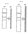
- Figures 3(A) and (B) and Figures 4(A) and (B) each are front and side views showing the shapes of test pieces for measuring shear load.
- a predetermined amount of minute inclusions 3 are first substantially uniformly scattered between metal plates 1 and 2. Then, the metal plates 1 and 2 are cold- or warm-pressed against each other between pressure rolls 4 and 4 to bite the minute inclusions 3 into the metal plates 1 and 2, whereby the metal plates 1 and 2 are joined together, while they are allowed to come into contact with each other, but are not metallurgically joined to each other, at their portion where the inclusions 3 are not present.
- the projection area of the joined portion with respect to the same surface as the aforesaid contact surface accounts for 0.5 to 50 % of the combined area of the metal plates 1 and 2 by the adjustment of the amount of the inclusions 3 to be scattered, etc. In this manner, a composite material serving as the vibration-damping metal sheet is obtained.
- the metal plates 1 and 2 are joined to each other, while the minute inclusions 3 nearly uniformly scattered therebetween bite thereinto, and the projection area of the portion of the metal plates 1 and 2 having the minute inclusions 3 bit thereinto, i.e. the joined portion (which may hereinafter be simply referred to as the joined area) amouts to 0.5 - 50 % or less of the combined area of the metal plates 1 and 2 (which correspond to the surface area of one side of one metal plate, and shall be hereinafter simply called the area of the metal plate).
- the joined area amouts to 0.5 - 50 % or less of the combined area of the metal plates 1 and 2 (which correspond to the surface area of one side of one metal plate, and shall be hereinafter simply called the area of the metal plate).
- the metal plates 1 and 2 are only allowed to contact each other, while not metallurgically joined to each other, at their portion where the inclusions 3 are not present, and which is to be subject to friction, thereby reducing vibrations and noises.
- the percentage of the joined area with respect to the area of the metal plate may simply be called the proportion of joined area).
- the joined area is calculated from distributions by sizes, obtained by forcedly separating the thus produced composite metal sheet into the original metal plates and measuring the sizes and quantities of the individual inclusions showing up on the separated surfaces of a given area.
- the vibration-damping properties increases with decreases in the joined area of the metal plates 1 and 2 having the minute inclusions 3 biting thereinto.
- too small a joined area gives rise to a reduction in the joint strength of the metal plates 1 and 2, which may in turn cause the metal sheet to deform at its end faces or to separate from each other between metal plates 1 and 2 during plastic working.
- the lower limit of the proportion of the joined area was set at 0.5 %.
- an increased joined area leads to an increase in the joint strength of the vibration-damping metal sheet, but rather results in a drop of the vibration-damping properties, so that the significance in making it in a composite structure is lost.
- the upper limit of the proportion of the joined area was set at 50 %.
- To join together the metal plates 1 and 2 by biting the minute inclusions 3 thereinto may be achieved by some techniques such as pressing or explosion pressing, in addition to pressure contact with the pressure rolls 4 and 4, as illustrated in Figure 1.
- some techniques such as pressing or explosion pressing, in addition to pressure contact with the pressure rolls 4 and 4, as illustrated in Figure 1.
- the most favorable technique is the pressure contact with the pressure rolls 4 and 4 in order to adjust the projection area of the joined portion to a desired value and permit the metal plates 1 and 2 to be not fixedly pressed against each other, i.e. come into pressure contact with each other, while not metallurgically joined together, at their portion where the minute inclusions 3 are not present.
- the diffusion annealing should preferably be carried out in a ferrite-phase region, when the metal plates 1 and 2 are formed of steel plates. However, it is preferable to carry out at a temperature equal to or higher than 650°C, since the rate of diffusion decreases at a lower temperature.
- the diffusion annealing should preferably be conducted at a temperature equal to or lower than 1,200°C. Within such a temperature range, the diffusion annealing should preferably be conducted for a sufficient time of 0.5 hours or longer.
- the metal plates 1 and 2 to be used may include various metal plates such as general-duty steel plates; special steel plates, e.g. carbon tool steel plates, stainless steel plates and nickel-chromium-molybdenum steel plates; non-ferrous metal plates, e.g. aluminium plates, copper plates, titanium plates and nickel plates; plated metal plates obtained by plating said general-duty steel plates, special steel plates and non-ferrous metal plates; and clad metal plates obtained by cladding of these metal plates.
- these metal plates may be subjected to desired hardening and heat treatments such as carburizing, nitriding, hardening and annealing to impart vibration-damping properties as well as abrasion resistance and toughness thereto.
- Both metal plates 1 and 2 joined to each other by the minute inclusions 3 need not be formed of the same material, and may optionally be formed of a combination of different materials, depending upon the purpose.
- minute inclusions 3 use may be made of any material which can bite into the metal plates 1 and 2 to join them together, such as metals, e.g. iron and ceramics in powder or finely wiry form and a network comprising such fine wires.
- the minute inclusions 3 may also consist only of a single-phase material (such as metals including alloys or ceramics), or may be coated on their surfaces with other metals. No particular limitation is placed on the type of the coating metals so far as the coating metals can bite into the metal plates 1 and 2 to join them together.
- the minute inclusions 3 are of metal or ceramic powders, then it is not especially required to adjust their particle size.
- their mean particle size is larger than that of metal powders for ordinary powder metallurgy.
- dents may show up on the surfaces of the metal plates 1 and 2 as if they come up from within, when they are joined together through such minute inclusions 3. Such dents may sometime impair the commercial value of the product.
- the particle size of the inclusions 3 is set at 1000 micrometers at most, and may be selected therefrom depending upon the purpose.
- the minimum particle size of the minute inclusions 3 should preferably be about 100 micrometers.
- the powders may be regarded as short wiry materials, and the diameter of the minute inclusions 3 is preferably in a range of 100 to 10000 micrometers in terms of the mean diameter in the vertical section with respect to their lengthwise direction.
- the vibration-damping properties were estimated in terms of the sound-pressure level measured by suspending a composite metal sheet X to be measured from a supporting frame 5 by means of threads 6 and allowing a hammer 7 rotatably mounted on an upper cross beam of said frame 5 by a bearing 8 to drop, while rotating, thereon from the horizontal state to receive at a microphone 9 a sound resulting from a blow struck upon the composite metal sheet X and determine the sound-pressure level by an amplifier 10, as illustrated in Figure 2.
- the mechanical properties were estimated in terms of the shear load obtained from the results of tensile tests conducted with test pieces, each being prepared by cutting off one side of a composite metal sheet of 20 mm in width and providing slits in the metal sheet to define a joined portion of 10 mm in length, as illustrated in Figures 3(A) and (B) or Figures 4(A) and (B).
- one-hour annealing was thereafter carried out at 850°C for low-carbon steel (SPCD) and 700°C for carbon tool steel (SK5) respectively.
- SPCD low-carbon steel
- SK5 carbon tool steel
- Host of the composite metal sheets in which SK5 were used were thermally refined in the following procedures, i.e. by one-hour annealing at 1,100°C, followed by hot-quenching at 800°C and tempering at 200°C.
- composite metal sheets having various proportions of joined area were made (Examples 1 to 11 & Comparison Examples 2,3 and 6 to 8).
- Table 3 shows the properties of the vibration-damping metal sheets, prepared according to the present invention the composite metal sheets in the Comparison Examples and the single sheet prepared as the comparative material.
- the vibration-damping metal sheets according to the present invention of the composite metal sheets made of low-carbon steel plates in Examples 1 to 7 and carbon tool steel plates in Examples 8 to 11 are lower in the sound-pressure level and, hence, higher in the vibration-damping properties than the single sheets in Comparison Examples 1, 4 and 5 and the composite sheets in Examples 3, 7 and 8 of which the proportion of joined area by biting of the minute inclusions of the iron powders exceeds 50 %. Since the difference between 20dB and 6dB in terms of sound-pressure level corresponds to that between 1/10 and 1/2 in terms of sound-pressure, how excellent are the vibration-damping metal sheets according to the present invention in the vibration-damping properties will be easily appreciated.
- Table 6 shows the properties of the sheets in Examples 12 to 14 and Comparative Examples 10 and 11 manufactured in this manner.
- the vibration-damping metal sheets accroding to the present invention in the Examples 12 to 14 are lower in the sound-pressure level and, hence, higher in the vibration-damping properties than the clad sheet in Comparative Example 9 in which no minute inclusion was used and the sheet in Comparative Example 11 which has a proportion of joined area by biting of the minute inclusions exceeding 50 %. From Comparative Example 10, it is found that when the proportion of joined area by biting of the minute inclusions is 0.4 %, the shear load of the sheet is so small that it is not suitable for any structural material.
- Table 9 shows the properties of the sheets manufactured in respective Examples and Comparative Examples.
- the vibration-damping metal sheets in Examples 23 to 26 according to the present invention are lower in the sound-pressure level and, hence, higher in the vibration-damping properties than Comparative Examples 15 and 16, and their vibration-damping properties are excellent.
- the vibration-damping metal sheets according to the present invention have excellent properties, as is the case with Examples 1 to 7 where the metal plates used were not plated.
- a clad sheet which was of the three-layer structure composed of aluminium plate - steel plate - aluminium plate, the steel plate being a low carbon plate having a chemical composition set forth in Table 11 and the aluminium plate having a chemical composition set forth in Table 12, each layer having thickness of 0.5mm-1.5mm-0.5mm and in the total thickness, 2.5 mm (Comparative Example 17 ).
- the vibration-damping metal sheets in Examples 35 to 40 according to the present invention are lower in the sound-pressure level and, hence, excellent in the vibration-damping properties than Comparative Example 21 and Comparative Example 23 in which the proportion of joined area exceeded 50 % by biting of the ceramic powders acting as the minute inclusions.
- the proportion of joined area by biting of the ceramic powders was 0.3 %, it spalled away easily with a small shock after rolling, and could not keep a state of joining. It is thus found that the effect of the present invention is had in the case wherein the ceramic powders as the minute inclusions is used as in the case wherein metal powders are used.
- the composite metal sheets were annealed at 700°C for two hours, and were then subjected to refining heat treatments involving hardening at 860°C and tempering at 200°C to manufacture composite metal sheets having various proportions of joined area (Examples 46 to 48 and Comparative Examples 26 to 27).
- the vibration-damping metal sheets in Examples 46 and 47 according to the present invention are lower in the sound-pressure level and, hence, excellent in the vibration-damping properties than the single sheet in Comparative Example 25 and Comparative Example 27 in which the proportion of joined area exceeded 50 %.
- Comparative Example 26 it is also found that in the case wherein the proportion of joined area is 0.4 %, difficulty is involved in using it as the structural material due to low shear load. From this, it is found that the effect of the present invention is had in the case wherein the wiry material is used as the minute inclusions as in the case wherein the powders are used.
- iron powders C specified in Table 25 were plated with Cu to form a 10 ⁇ m-thick layer on their surfaces, and varied amounts of such minute inclusions were uniformly scattered between the aforesaid two steel plates, which were cold-rolled to have a finished thickness of 1.6 mm for a finished plate of low carbon steel and 3.2 mm for a finished plate of carbon tool steel to obtain composite metal sheets.
- one-hour annealing at 800 °C and two-hour annealing at 900 °C were carried out for low carbon steel and carbon tool steel, respectively, to thereby manufacture composite metal sheets having various proportions of joined area (Examples 53 to 61 and Comparative Examples 31, 32, 34 and 35).
- the vibration-damping metal sheets in Examples 53 to 61 according to the present invention are excellent as compared with those Comparative Examples 30 to 35 where the metal plates of the same type of steel were used and can be used as structural materials, having both vibration-damping properties and joint strength. It is thus found that the effect of the present invention is had, or increased effect thereof is had in the case wherein the materials plated with Cu etc. are used as the minute inclusions as in the case wherein the inclusions not plated are used.
- the vibration-damping metal sheets of the present invention more than half of the area of the metal plates is occupied by the area of the metal plates at which they are not joined together, but simply come into contact with each other, and the friction occurring between the metal plates at this area assures excellent vibration-damping properties. Further, since the minute inclusions with which the joined portion is made of are formed of materials of heat-resistant metals or ceramics, rather than materials which are poor in heat resistance such as plastic materials, it is very unlikely that the structure and vibration-damping properties of the composite metal sheets may be destructed and deteriorated by heat treatments to be applied depending upon the purpose or by the use thereof in high-temperature environment, and high shear force is maintained between the metal plates.
- the composite metal sheets of the present invention possess sufficiently high conductivity as well as weldability, since the metal plates come into contact with each other at the portion at which the minute inclusions are not present.
- vibration-damping metal sheets according to the present invention possess such excellent physical properties, they are best-suited for use not only for foundation metals and gears of diamond cutters or chip saws used as a high speed rotator but also for structural materials needed to have vibration-damping properties as well as heat resistance, weldability and toughness such as working structures in automobiles etc.
Abstract
Claims (10)
Applications Claiming Priority (4)
| Application Number | Priority Date | Filing Date | Title |
|---|---|---|---|
| JP142709/86 | 1986-06-20 | ||
| JP14270986 | 1986-06-20 | ||
| JP180151/86 | 1986-08-01 | ||
| JP61180151A JPH0659707B2 (ja) | 1986-06-20 | 1986-08-01 | 制振金属板 |
Publications (3)
| Publication Number | Publication Date |
|---|---|
| EP0275316A1 EP0275316A1 (fr) | 1988-07-27 |
| EP0275316A4 EP0275316A4 (fr) | 1989-06-21 |
| EP0275316B1 true EP0275316B1 (fr) | 1992-05-13 |
Family
ID=26474627
Family Applications (1)
| Application Number | Title | Priority Date | Filing Date |
|---|---|---|---|
| EP87904099A Expired - Lifetime EP0275316B1 (fr) | 1986-06-20 | 1987-06-18 | Plaque metallique d'amortissement de vibrations |
Country Status (4)
| Country | Link |
|---|---|
| US (1) | US4873149A (fr) |
| EP (1) | EP0275316B1 (fr) |
| GB (1) | GB2201624B (fr) |
| WO (1) | WO1987007872A1 (fr) |
Families Citing this family (20)
| Publication number | Priority date | Publication date | Assignee | Title |
|---|---|---|---|---|
| DE3834829A1 (de) * | 1988-10-13 | 1990-04-19 | Hoesch Stahl Ag | Widerstandsschweissbarer verbundwerkstoff |
| US5281470A (en) * | 1991-03-01 | 1994-01-25 | Cci Co., Ltd. | Vibration damper |
| AUPQ078899A0 (en) * | 1999-06-04 | 1999-06-24 | Ceramic Fuel Cells Limited | A fuel cell gas separator |
| KR100498462B1 (ko) * | 2002-11-22 | 2005-07-01 | 삼성전자주식회사 | 댐핑 장치 |
| JP2006022930A (ja) * | 2004-07-09 | 2006-01-26 | Matsushita Electric Ind Co Ltd | 動圧流体軸受装置 |
| US7510621B2 (en) * | 2004-09-22 | 2009-03-31 | General Motors Corporation | Conductive adhesive bonding |
| US20060062977A1 (en) * | 2004-09-22 | 2006-03-23 | Sigler David R | Bonded lightweight structural sheet |
| US20060134450A1 (en) * | 2004-12-20 | 2006-06-22 | Sigler David R | Additives for improved weldable composites |
| US7833630B2 (en) * | 2004-12-20 | 2010-11-16 | Gm Global Technology Operations, Inc. | Weldable metal composites and methods |
| US20070295704A1 (en) * | 2004-12-20 | 2007-12-27 | Gm Global Technology Operations, Inc. | Additives for improved weldable composites |
| CN105034482B (zh) | 2008-08-18 | 2017-08-25 | 多产研究有限责任公司 | 可成型的轻质复合材料 |
| CA2822748C (fr) | 2009-12-28 | 2021-06-01 | Shimon Mizrahi | Procedes pour souder des materiaux composites et articles produits par celui-ci |
| US9415568B2 (en) | 2010-02-15 | 2016-08-16 | Productive Research Llc | Formable light weight composite material systems and methods |
| CN105415769B (zh) | 2011-02-21 | 2019-07-16 | 多产研究有限责任公司 | 包括不同性能的区域的复合材料和方法 |
| JP2013147004A (ja) * | 2012-01-23 | 2013-08-01 | Hitachi Cable Ltd | 複合材 |
| JP2013184380A (ja) * | 2012-03-08 | 2013-09-19 | Hitachi Cable Ltd | 制振複合材 |
| US9233526B2 (en) | 2012-08-03 | 2016-01-12 | Productive Research Llc | Composites having improved interlayer adhesion and methods thereof |
| CN105109146B (zh) * | 2015-08-24 | 2017-11-10 | 青岛理工大学 | 嵌入阻尼薄膜的金属夹层板制作工艺 |
| US11338552B2 (en) | 2019-02-15 | 2022-05-24 | Productive Research Llc | Composite materials, vehicle applications and methods thereof |
| DE102023002027A1 (de) | 2023-05-19 | 2024-01-18 | Mercedes-Benz Group AG | Verfahren zur Herstellung eines Metall-Keramik-Komposit-Bauteils sowie das Metall-Keramik-Komposit-Bauteil |
Family Cites Families (18)
| Publication number | Priority date | Publication date | Assignee | Title |
|---|---|---|---|---|
| USRE22373E (en) | 1943-09-14 | Manufacture of abrasive articles | ||
| US22373A (en) * | 1858-12-21 | James montgomery | ||
| US2244771A (en) * | 1938-08-16 | 1941-06-10 | Int Standard Electric Corp | Composite conductor and contact between conductors |
| US2285583A (en) * | 1940-04-13 | 1942-06-09 | Westinghouse Electric & Mfg Co | Surface preparation of bearings for babbitting |
| US2292991A (en) * | 1941-03-06 | 1942-08-11 | Behr Manning Corp | Flexible abrasive product |
| US2490548A (en) * | 1945-07-07 | 1949-12-06 | Gen Motors Corp | Method of making composite articles |
| US2627649A (en) * | 1948-08-07 | 1953-02-10 | Burndy Engineering Co Inc | Method for making connectors with hard particle lining |
| US3406446A (en) * | 1963-10-29 | 1968-10-22 | Stephen A. Muldovan | Method of manufacturing laminated metal panel |
| US3620880A (en) * | 1969-04-07 | 1971-11-16 | Jerome H Lemelson | Apparatus and method for producing composite materials |
| JPS5025426B1 (fr) * | 1969-05-23 | 1975-08-23 | ||
| FR2162317A1 (en) * | 1971-12-06 | 1973-07-20 | Bennes Marrel | Composite sheet with lightweight material - esp for vehicle bodies containers and material handling skips |
| US4005991A (en) * | 1971-12-29 | 1977-02-01 | Toyo Kogyo Co., Ltd. | Metal made of steel plate and aluminum material |
| US3860443A (en) * | 1973-03-22 | 1975-01-14 | Fiber Materials | Graphite composite |
| JPS52138017A (en) * | 1976-05-14 | 1977-11-17 | Taiho Kogyo Co Ltd | Compound material of aluminium group casting base and ferrous group annexation and its production method |
| JPS5724459Y2 (fr) * | 1979-04-18 | 1982-05-27 | ||
| DE3000171C2 (de) * | 1980-01-04 | 1982-04-29 | Vereinigte Aluminium-Werke Ag, 5300 Bonn | Faserverstärkter Verbundwerkstoff und Verfahren zu seiner Herstellung |
| JPS58199138A (ja) * | 1982-05-14 | 1983-11-19 | 株式会社丸三パツキング製作所 | 複合超塑性材料 |
| US4565744A (en) * | 1983-11-30 | 1986-01-21 | Rockwell International Corporation | Wettable coating for reinforcement particles of metal matrix composite |
-
1987
- 1987-06-18 US US07/177,524 patent/US4873149A/en not_active Expired - Fee Related
- 1987-06-18 WO PCT/JP1987/000402 patent/WO1987007872A1/fr active IP Right Grant
- 1987-06-18 EP EP87904099A patent/EP0275316B1/fr not_active Expired - Lifetime
- 1987-06-18 GB GB8803738A patent/GB2201624B/en not_active Expired - Lifetime
Also Published As
| Publication number | Publication date |
|---|---|
| GB8803738D0 (en) | 1988-04-07 |
| WO1987007872A1 (fr) | 1987-12-30 |
| EP0275316A1 (fr) | 1988-07-27 |
| GB2201624B (en) | 1990-10-17 |
| EP0275316A4 (fr) | 1989-06-21 |
| GB2201624A (en) | 1988-09-07 |
| US4873149A (en) | 1989-10-10 |
Similar Documents
| Publication | Publication Date | Title |
|---|---|---|
| EP0275316B1 (fr) | Plaque metallique d'amortissement de vibrations | |
| EP0060083B1 (fr) | Tôle d'acier plaqué de titane | |
| US4340650A (en) | Multi-layer composite brazing alloy | |
| US6722002B1 (en) | Method of producing Ti brazing strips or foils | |
| EP1257383B1 (fr) | Procede de realisation d'un joint entre du cuivre et de l'acier inoxydable | |
| EP1270753A1 (fr) | Matériau fritté et élément de contact en composite fritté | |
| GB2360294A (en) | A copper based sliding material | |
| GB1583638A (en) | Multi-layer metal bearings | |
| US3732083A (en) | Composite article | |
| Shi et al. | Unlubricated rolling-sliding wear mechanisms of complex aluminium bronze against steel | |
| Sherby et al. | Superplastic bonding of ferrous laminates | |
| JP2551981B2 (ja) | 複層鉄銅鉛系合金軸受材料 | |
| Sherby et al. | Multilayered composites based on ultrahigh carbon steel and brass | |
| JP2508862B2 (ja) | 熱間継目無管製造用プラグ | |
| Raybould | Wear-Resistant Al—Steel—Pb Admixed Alloys Produced by Dynamic Compaction | |
| JPS63242635A (ja) | 制振金属板 | |
| JPH11501105A (ja) | オーバーレイ付き平軸受 | |
| DE3327657A1 (de) | Verfahren zur herstellung von aluminium-verbundwerkstoffen | |
| JPS63246238A (ja) | 制振金属板及びその製造方法 | |
| JP2691456B2 (ja) | 複合型制振鋼板の製造方法 | |
| Yılmaz | Effect of welding parameters on diffusion bonding of type 304 stainless steel–copper bimetal | |
| JP3355199B2 (ja) | アーク溶射用ワイヤ | |
| JPH0659707B2 (ja) | 制振金属板 | |
| JP2681395B2 (ja) | 複合型制振鋼板の製造法 | |
| JP2680616B2 (ja) | 複合ロール |
Legal Events
| Date | Code | Title | Description |
|---|---|---|---|
| PUAI | Public reference made under article 153(3) epc to a published international application that has entered the european phase |
Free format text: ORIGINAL CODE: 0009012 |
|
| 17P | Request for examination filed |
Effective date: 19880217 |
|
| AK | Designated contracting states |
Kind code of ref document: A1 Designated state(s): DE FR |
|
| A4 | Supplementary search report drawn up and despatched |
Effective date: 19890621 |
|
| 17Q | First examination report despatched |
Effective date: 19910731 |
|
| GRAA | (expected) grant |
Free format text: ORIGINAL CODE: 0009210 |
|
| AK | Designated contracting states |
Kind code of ref document: B1 Designated state(s): DE FR |
|
| REF | Corresponds to: |
Ref document number: 3779093 Country of ref document: DE Date of ref document: 19920617 |
|
| ET | Fr: translation filed | ||
| PLBE | No opposition filed within time limit |
Free format text: ORIGINAL CODE: 0009261 |
|
| STAA | Information on the status of an ep patent application or granted ep patent |
Free format text: STATUS: NO OPPOSITION FILED WITHIN TIME LIMIT |
|
| 26N | No opposition filed | ||
| PGFP | Annual fee paid to national office [announced via postgrant information from national office to epo] |
Ref country code: FR Payment date: 19960611 Year of fee payment: 10 |
|
| PGFP | Annual fee paid to national office [announced via postgrant information from national office to epo] |
Ref country code: DE Payment date: 19960627 Year of fee payment: 10 |
|
| PG25 | Lapsed in a contracting state [announced via postgrant information from national office to epo] |
Ref country code: FR Free format text: LAPSE BECAUSE OF NON-PAYMENT OF DUE FEES Effective date: 19980227 |
|
| PG25 | Lapsed in a contracting state [announced via postgrant information from national office to epo] |
Ref country code: DE Free format text: LAPSE BECAUSE OF NON-PAYMENT OF DUE FEES Effective date: 19980303 |
|
| REG | Reference to a national code |
Ref country code: FR Ref legal event code: ST |
|
| REG | Reference to a national code |
Ref country code: FR Ref legal event code: ST |