EP0274862B1 - Kupplung für Ostomiebeutel - Google Patents
Kupplung für Ostomiebeutel Download PDFInfo
- Publication number
- EP0274862B1 EP0274862B1 EP87310740A EP87310740A EP0274862B1 EP 0274862 B1 EP0274862 B1 EP 0274862B1 EP 87310740 A EP87310740 A EP 87310740A EP 87310740 A EP87310740 A EP 87310740A EP 0274862 B1 EP0274862 B1 EP 0274862B1
- Authority
- EP
- European Patent Office
- Prior art keywords
- coupling
- radially
- ostomy
- annular channel
- parts
- Prior art date
- Legal status (The legal status is an assumption and is not a legal conclusion. Google has not performed a legal analysis and makes no representation as to the accuracy of the status listed.)
- Expired - Lifetime
Links
- 230000008878 coupling Effects 0.000 title claims abstract description 90
- 238000010168 coupling process Methods 0.000 title claims abstract description 90
- 238000005859 coupling reaction Methods 0.000 title claims abstract description 90
- 230000002093 peripheral effect Effects 0.000 claims abstract description 30
- 239000000463 material Substances 0.000 claims abstract description 12
- 229920003023 plastic Polymers 0.000 claims abstract description 10
- 239000004033 plastic Substances 0.000 claims abstract description 10
- 238000007789 sealing Methods 0.000 claims description 4
- 239000000853 adhesive Substances 0.000 description 6
- 230000001070 adhesive effect Effects 0.000 description 6
- 230000015572 biosynthetic process Effects 0.000 description 3
- 238000001746 injection moulding Methods 0.000 description 3
- 229920001684 low density polyethylene Polymers 0.000 description 3
- 239000004702 low-density polyethylene Substances 0.000 description 3
- 238000010276 construction Methods 0.000 description 2
- 239000007788 liquid Substances 0.000 description 2
- 230000004323 axial length Effects 0.000 description 1
- DQXBYHZEEUGOBF-UHFFFAOYSA-N but-3-enoic acid;ethene Chemical compound C=C.OC(=O)CC=C DQXBYHZEEUGOBF-UHFFFAOYSA-N 0.000 description 1
- 239000005038 ethylene vinyl acetate Substances 0.000 description 1
- 229920002457 flexible plastic Polymers 0.000 description 1
- 239000012530 fluid Substances 0.000 description 1
- 239000007789 gas Substances 0.000 description 1
- 238000007455 ileostomy Methods 0.000 description 1
- 230000001771 impaired effect Effects 0.000 description 1
- 238000000034 method Methods 0.000 description 1
- 229920001200 poly(ethylene-vinyl acetate) Polymers 0.000 description 1
- 239000007787 solid Substances 0.000 description 1
- 108010001894 stomadhesive Proteins 0.000 description 1
- 239000000126 substance Substances 0.000 description 1
- 238000011477 surgical intervention Methods 0.000 description 1
- 239000002699 waste material Substances 0.000 description 1
Images


Classifications
-
- A—HUMAN NECESSITIES
- A61—MEDICAL OR VETERINARY SCIENCE; HYGIENE
- A61F—FILTERS IMPLANTABLE INTO BLOOD VESSELS; PROSTHESES; DEVICES PROVIDING PATENCY TO, OR PREVENTING COLLAPSING OF, TUBULAR STRUCTURES OF THE BODY, e.g. STENTS; ORTHOPAEDIC, NURSING OR CONTRACEPTIVE DEVICES; FOMENTATION; TREATMENT OR PROTECTION OF EYES OR EARS; BANDAGES, DRESSINGS OR ABSORBENT PADS; FIRST-AID KITS
- A61F5/00—Orthopaedic methods or devices for non-surgical treatment of bones or joints; Nursing devices ; Anti-rape devices
- A61F5/44—Devices worn by the patient for reception of urine, faeces, catamenial or other discharge; Colostomy devices
- A61F5/445—Colostomy, ileostomy or urethrostomy devices
- A61F5/448—Means for attaching bag to seal ring
Definitions
- This invention relates to a coupling for joining an ostomy bag to a pad or surgical dressing.
- Ostomy bags are usually secured to a pad or surgical dressing which contacts the user's skin and surrounds the stoma.
- the term 'ostomy bag' is intended to include colostomy, ileostomy, urostomy and other bags used for example after surgical intervention procedures.
- There is a need for a coupling between pad and bag which allows the bag to be readily removed when necessary, and replaced by a clean, empty bag. At the same time, it is essential that the coupling should be a secure one, and prevent leakage particularly of liquids and gases.
- GB-A-1 099 455 discloses an appliance in which one ring co-operates with a second part-ring which is used to trap the neck of a bag when the two rings are inter-engaged with the bag mouth between them. If adequate security against leakage is to be provided, it is necessary that the two rings should be a tight fit; however, this makes it difficult for the user to pull off the part-ring. As the part-ring is pulled off, there is the probability that the security of attachment of the first ring to the surgical dressing, or of the dressing to the skin of the wearer, will be impaired. This may also cause discomfort to the wearer.
- the present inventor in GB-A-2 163 350 disclosed an ostomy appliance having interengaging coupling elements.
- One coupling element is formed by an annular plate defining a stomal orifice, the plate having projecting from a surface thereof an engaging member formed of two ribs which diverge from each other in a direction away from the plate.
- the ribs are made of a resilient flexible plastics material. At least one of them has at its distal region a stepped formation intended for engagement with co-operating formation on the bag side coupling element.
- the two coupling elements can be pushed together or pulled apart using only a moderate force such as can easily be applied manually by an elderly or infirm person.
- the preamble of claim 1 herein is based upon this document.
- the present invention does not rely on a stepped interengaging formation to hold the two coupling parts together.
- the aim of the invention is to provide an ostomy coupling which is at the same time easy to fit and remove and of such a flat construction that it meets all reasonable requirements for unobtrusiveness when worn.
- a two part ostomy coupling the cooperating two parts of which each have radially inner and outer peripheral walls and thus form an annular channel, the rims of the peripheral walls of one of the parts being formed by respective flexible resilient elements of plastics material integral with the remainder of the said one part, characterised in that the other of the parts is formed as a shallow annular channel, and the peripheral elements of the said one part are shaped to taper in radially outward and inward directions respectively, so that the said one part is a push fit into the shallow channel of the said other part.
- This arrangement of the peripheral elements allows one of the elements to be "sprung” past the projection when the two parts of the coupling are assembled together. This assembly may be done by a simple manual pressing together.
- the radially inner wall defining the shallow channel is preferably angled slightly radially inwardly over a part of its height. The purpose of this is to give a lead-in guide and facilitate the manual fitting together of the first and second coupling parts.
- an ostomy coupling the cooperating two parts of which each have radially inner and outer peripheral walls and thus form an annulus
- the first one of the parts defining an annular channel and the rim of the radially inner peripheral wall of the second part being formed by a flexible resilient element of plastics material integral with the remainder of the second part, characterised in that the first part is formed as a shallow annular channel and in that the resilient element of the second part is a strip tapering and extending in a radially-inward direction and tilted out of the plane of the remainder of the second part, and in that the rim of the radially outer peripheral wall of the second part is formed by an element integral with the remainder which element can engage under a rim portion of the outer peripheral wall of the said first part, so that the said second part is a push fit into the shallow channel of the first part.
- the bag side coupling part may be constructed to include a filter housing, in accordance with the teaching of our co-pending EP-A-210032.
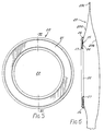
- the illustrated ostomy bag coupling comprises a first part 10 and a second part 20.
- the first coupling part 10 is the body-side coupling part and the second part 20 is the bag side coupling part.
- the first part 10 could be the bag side coupling part and the second part 20 could be the body-side coupling part. In that event, of course the ostomy bag would be secured to the first coupling part 10.
- the illustrated body-side coupling part 10 is preferably made by injection moulding from low density polyethylene. It may alternatively be moulded from E.V.A. (ethylene vinyl acetate) or from a low density polyethylene with some added E.V.A.
- the coupling part 10 includes a flat annulus 11 having a radially inner wall 12 and a peripheral wall 13. It has a stomal aperture 14. In use it is attached to a pad of medical grade adhesive 15. Suitable adhesive materials for this purpose include, for example, those described by Chen in US-A-3 339 546; by Chen et al. in US-A-4 192 785; by Pawelchak et al.
- the pad 15 may be provided with a stomal aperture 15a or such an aperture may be cut in a complete pad by the user just prior to applying it to his or her peristomal area.
- the peripheral wall 13 has a continuous inwardly projecting projection 16 thereon, the extent of its projection radially inwardly being in the region 0.1-0.2 mm (0.004-0.008 inches).
- the radially inner wall 12 has a portion 17 remote from the annulus 11 which is angled radially inwardly as best seen in Figure 3. For example, it may be angled radially inward at an angle of between 25 - 60 o to the remainder of the wall 12.
- This angled portion 17 provides a lead-in guide when the bag side coupling part is being coupled to the body side coupling part, an operation which is easily done with a gentle manual press fitting.
- the illustrated bag side coupling part 20 is preferably made from the synthetic plastics material known as E.V.A.
- E.V.A. Grade UL 00209 sold by Esso Chemicals The coupling, part 20 includes a flat annulus 21 having a stomal aperture 22.
- An ostomy bag 23 is attached to one surface 24 of the flat annulus for example by a weld seam 25.
- the bag side coupling part 20 has radially inner and outer rims formed by respective flexible peripheral elements 26 and 27. As seen best in Figure 7, these flexible elements are angled to the plane of the annulus 21, for example at an angle between 40 o and 60 o , preferably 50 o to the said plane.
- the flexible elements taper in a direction away from the remainder of the annulus.
- the whole part 20 is integral and made by injection moulding.
- the tips of the flexible elements 26 and 27 stand proud of the surface 24 of the body side coupling part 20 by a distance which is from about 40-70% of the thickness of the annulus 21.
- this particular ratio is not essential to the invention.
- the ostomy bag 23 as seen in Figure 6 has bag walls 23a, 23b, joined by a peripheral weld seam 23c and the wall 23a has a stomal aperture therein, and surrounding that aperture there is the weld seam 25 which connects the bag wall 23a to the annulus 21.
- the stoma aperture 22 of the bag side coupling part is approximately aligned with the stomal aperture 14 and the radially inner rim of the annulus 21 defined by the flexible flange 27 is guided by the wall portion 17 so that the bag side coupling part becomes fully aligned with the body side coupling part. Thereafter, gentle pressure suffices to connect these two parts and in the connected condition, the radially outer flange 26 engages under the projection 16 on the wall 13.
- an effective ostomy coupling can be obtained which is at the same time easy to fit and remove and of such a flat construction that it meets all reasonable requirements for unobtrusiveness when worn.
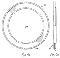
- Figure 9 illustrates a body side coupling part 80, intended to co-operate with a bag side coupling part 100 which is shown in Figure 10.
- a bag retaining ring 120 which is shown in Figure 11.
- Figures 9A and 9B are, on a smaller scale, respectively elevation view and half axial cross section of the body side coupling part shown in Figure 9.
- the body side part 80 may be made by injection moulding of low density polyethylene, and in use is attached to a pad of medical grade adhesive (not shown in Figures 9-12) in a similar way as is shown in the embodiment of Figures 1-4.
- the body side part 80 includes a substantially flat annulus 81 having a radially inner wall 82 upon which is a lead-in slope or chamfer 82 a , and a radially outer wall 83.
- the stomal aperture is indicated at 84.
- the wall 83 has an inturned rim portion 83 a .
- the height (i.e. axial length) of the wall 82 is preferably about 3.2mm (0.125") approx and that of the wall 83 is preferably about 1.9mm (0.075”) approx.
- the bag side part 100 may be made of E.V.A. synthetic plastics and includes an annular portion 101, a radially inner wall portion 102 having a resilient flexible encircling strip 102 a at its inner periphery and a radially outer engagement portion 104.
- the latter has a radially outwardly extending lip or rim 104 a which, when the two coupling parts are connected, hooks under the inturned rim portion 83 a of the body side coupling part 80.
- the rim portion 83 a is preferably relatively rigid.
- the rim 83 a extends around the whole periphery of the engagement portion 104; in alternative embodiments of the invention a series of peripherally-spaced lips could be used instead of the continuous rim 83 a . In other words, a castellated rim could be employed. This could be of use when it is desired to have the parts 80 and 100 separable by application of a slight force.
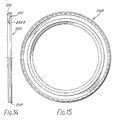
- the radially outer part of the engagement portion 104 has a stepped configuration providing a channel 105 for receiving the radially inner edge 121 of the belt retaining ring 120.
- the portion 101 also has a flange portion 106.
- the bag is attached in a conventional way to the annular surface 107.
- the annular bag side coupling part 100 is seen in its undeformed condition in Figure 10 and in this condition the encircling flexible strip 102 a extends at about 50 degrees (other angles may be suitable) to the axis of rotation of the coupling part 100.
- this strip 102 a When assembled into the channel-shaped part 80, as can be done with light manual pressure, this strip 102 a is bent towards the adjacent portion 102.
- the parts 80 and 100 in their assembled positions are coupled together due to the interengagement at 83 a , 104 a and the strip 102 a is flexed inwardly from its normal undeformed postion. Due to its resilience, it presses against the outer surface 82 b of the wall 82. This tends to urge the lip or rim 104 a under the interned rim 83 a and so increases the security of attachment between the two coupling parts 80 and 100. It also improves the fluid seal between these two parts.
- the ring 120 is connected to a belt or truss in conventional manner and aids in holding the appliance in the correct position on the wearer's body.
- the strip 102 a may extend substantially linearly from the adjacent root portion 102 b of the wall portion 102, at an angle (from about 20-60 o would be suitable) to the axis of rotational symmetry of the part 100. Alternatively it may extend arcuately from the root portion 102 b , but in either event it is desirable that the distance measured transverse to the axis between the radially innermost part of the strip 102 a and the radially outermost part of the rim 104 a should be from 100.2% to 103% of the distance between the surfaces 82 b and 83 b ( Figure 9) of the walls 82, 83.
- the invention is not limited to these particular values; other values may be employed, e.g. if different plastics materials are used.
- the part 100 contains a substantial recess 108 of annular channel shape. This is optional and could be dispensed with by making the part 100 largely a solid annulus, but it is included in the interest of saving material.
- the belt retaining ring need not be used in cases where the security of attachment of the medical grade adhesive pad to the wearer is adequate.
- apertured lugs may be provided on or formed integrally with either the body side or bag side coupling part.
- the illustrated belt retaining ring 120 has lugs 122 through the apertures 124 of which one threads or clips a suitable belt or harness, in conventional manner.
- Figure 11A is a central cross-section through the ring 120.
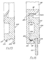
- FIG. 13-16 A third embodiment of the invention is illustrated in Figures 13-16.
- the bag side coupling part 200 has a flexible peripheral seal strip 210 instead of the rim 104 a .
- the seal strip 210 peripherally encircles the member 200 and tapers in a direction away from its root end 211 where it is connected to the remainder of the part 200.
- the strip 210 is preferably moulded integrally with the rest of the part 200 but may alternatively be separately attached e.g. by adhesive.
- the coupling part 200 co-operates with a body side coupling part 80.
- This embodiment of the invention retains the low profile advantage of the Figure 10 embodiment and has the further advantage that the liquid sealing between the parts 80 and 200 is enhanced by the presence of the seal strip 210. It is preferred that the overall dimension in the direction normal to the axis of rotational symmetry between the radially innermost part of strip 102 a and the radially outermost part of strip 110 should be from 100.5% to 104% of the distance between the surfaces 82 b , 83 b of the walls 82, 83. These proportions, however, are not crucial to the invention.
Landscapes
- Health & Medical Sciences (AREA)
- Epidemiology (AREA)
- Nursing (AREA)
- Orthopedic Medicine & Surgery (AREA)
- Engineering & Computer Science (AREA)
- Biomedical Technology (AREA)
- Heart & Thoracic Surgery (AREA)
- Vascular Medicine (AREA)
- Life Sciences & Earth Sciences (AREA)
- Animal Behavior & Ethology (AREA)
- General Health & Medical Sciences (AREA)
- Public Health (AREA)
- Veterinary Medicine (AREA)
- Orthopedics, Nursing, And Contraception (AREA)
- Medicines Containing Antibodies Or Antigens For Use As Internal Diagnostic Agents (AREA)
- Dental Preparations (AREA)
- Solid-Sorbent Or Filter-Aiding Compositions (AREA)
- Transition And Organic Metals Composition Catalysts For Addition Polymerization (AREA)
Claims (10)
- Zweiteilige Ostomiekupplung, deren zusammenwirkende zwei Teile, ein erstes Teil (10) und ein zweites Teil (20), jeweils radial innere und äußere Umfangswände (12, 13; 26, 27) aufweisen und dadurch eine ringförmige Nut bilden, wobei die Ränder der Umfangswände des zweiten Teils (20) durch jeweilige flexible, elastische Elemente (26, 27) aus Kunststoffmaterial gebildet werden, die einstückig mit dem Rest des zweiten Teils (20) verbunden sind, dadurch gekennzeichnet, daß das erste Teil (10) als flache, ringförmige Nut ausgebildet ist und die Umfangselemente (26, 27) des zweiten Teils (20) radial nach außen bzw. nach innen gerichtet sich verjüngen, so daß das zweite Teil (20) eine Schiebepassung in die flache Nut des ersten Teils (10) bildet.
- Kupplung nach Anspruch 1, wobei jedes der sich verjüngenden Elemente (26, 27) von der Ebene des Rests der zweiten flachen, ringförmigen Nut (21) schräg nach außen verläuft.
- Kupplung nach Anspruch 1 oder 2, wobei die radial äußere Wand der ersten flachen, ringförmigen Nut (11) einen radial einwärts gerichteten Vorsprung (16 oder 83a) an oder in der Nähe seines Rands vom flachen Ring (11 oder 81) entfernt aufweist.
- Kupplung nach einem der Ansprüche 1 - 3, wobei die radial innere Wand der ersten flachen, ringförmigen Nut (11) über einen Teil ihrer Höhe (bei 17) leicht radial einwärts abgewinkelt ist, so daß sie beim Gebrauch als Einlaufführung dient, wodurch das manuelle Befestigen des ersten und des zweiten Kupplungsteils (10 und 20) miteinander erleichtert wird.
- Zweiteilige Ostomiekupplung, deren beide zusammenwirkenden Teile, ein erstes Teil (80) und ein zweites Teil (100, 200), jeweils radial innere- und äußere Umfangswände aufweisen und dadurch einen Ring bilden, wobei das erste Teil (80) eine ringförmige Nut definiert und wobei der Rand der radial inneren Umfangswand des zweiten Teils (100, 200) aus einem flexiblen, elastischen Element aus Kunststoffmaterial gebildet wird, das einstückig mit dem Rest des zweiten Teils (100, 200) verbunden ist, dadurch gekennzeichnet, daß das erste Teil (80) als flache ringförmige Nut ausgebildet ist, daß das elastische Element des zweiten Teils (100, 200) ein Streifen (102a, 202a) ist, der sich verjüngend radial einwärts gerichtet erstreckt und von der Ebene des übrigen zweiten Teils (100, 200) herausgeneigt ist, daß der Rand der radial äußeren Umfangswand des zweiten Teils (100, 200) durch ein mit dem Rest einstückig verbundenes Element (104a, 210) gebildet wird, das unter einen Randabschnitt (83a) der äußeren Umfangswand (83) des ersten Teils (80) eingreifen kann, so daß der zweite Teil (100, 200) eine Schiebepassung in die flache Nut des ersten Teils (80) bildet.
- Ostomiekupplung nach Anspruch 5, dadurch gekennzeichnet, daß das Element (210) an der radial äußeren Umfangswand des zweiten Teils (200) aus einem flexiblen, elastischen, sich nach außen verjüngenden Dichtstreifen (210) gebildet wird, der sich von der radial äußeren Kante des zweiten Teils nach außen erstreckt, und aus einem Element (202a) gebildet wird, das sich von der radial inneren Kante des zweiten Teils aus erstreckt und das in einen gegenüberliegenden Abschnitt der inneren Umfangswand (82) eingreifen kann.
- Ostomiekupplung nach Anspruch 5 oder 6 mit einem Gurtrückhaltering (120)
- Ostomiekupplung nach Anspruch 7, wobei das zweite Kupplungsteil (100, 200) in Umfangsrichtung eine Nut aufweist, die so bemessen ist, daß sie die Innenkante des Gurtrückhalterings (120) aufnimmt.
- Ostomiekupplung nach Anspruch 1 oder 5, wobei das erste Kupplungsteil ein beutelseitiges Kupplungsteil und das zweite Kupplungsteil ein körperseitiges Kupplungsteil ist.
- Ostomiekupplung nach Anspruch 1 oder 5, wobei das erste Kupplungsteil ein körperseitiges Kupplungsteil und das zweite Kupplungsteil ein beutelseitiges Kupplungsteil ist.
Priority Applications (1)
| Application Number | Priority Date | Filing Date | Title |
|---|---|---|---|
| AT87310740T ATE84410T1 (de) | 1986-12-09 | 1987-12-07 | Kupplung fuer ostomiebeutel. |
Applications Claiming Priority (2)
| Application Number | Priority Date | Filing Date | Title |
|---|---|---|---|
| GB868629424A GB8629424D0 (en) | 1986-12-09 | 1986-12-09 | Ostomy bag coupling |
| GB8629424 | 1986-12-09 |
Publications (2)
| Publication Number | Publication Date |
|---|---|
| EP0274862A1 EP0274862A1 (de) | 1988-07-20 |
| EP0274862B1 true EP0274862B1 (de) | 1993-01-13 |
Family
ID=10608712
Family Applications (1)
| Application Number | Title | Priority Date | Filing Date |
|---|---|---|---|
| EP87310740A Expired - Lifetime EP0274862B1 (de) | 1986-12-09 | 1987-12-07 | Kupplung für Ostomiebeutel |
Country Status (15)
| Country | Link |
|---|---|
| US (1) | US4931045A (de) |
| EP (1) | EP0274862B1 (de) |
| JP (1) | JP2582819B2 (de) |
| AT (1) | ATE84410T1 (de) |
| AU (1) | AU599724B2 (de) |
| CA (1) | CA1294505C (de) |
| DE (1) | DE3783595T2 (de) |
| DK (1) | DK644087A (de) |
| ES (1) | ES2037096T3 (de) |
| GB (2) | GB8629424D0 (de) |
| IE (1) | IE63945B1 (de) |
| NO (1) | NO172623C (de) |
| NZ (1) | NZ222662A (de) |
| WO (1) | WO1988004162A1 (de) |
| ZA (1) | ZA878818B (de) |
Families Citing this family (32)
| Publication number | Priority date | Publication date | Assignee | Title |
|---|---|---|---|---|
| NZ229330A (en) * | 1988-06-13 | 1992-07-28 | Squibb & Sons Inc | Ostomy bag coupling: projections lock in slots |
| GB2237993A (en) * | 1989-11-17 | 1991-05-22 | Squibb & Sons Inc | Ostomy coupling |
| US5088992A (en) * | 1990-05-30 | 1992-02-18 | Edwards John V | Ostomy device with improved coupling system |
| GB9020218D0 (en) * | 1990-09-15 | 1990-10-24 | Smiths Industries Plc | Medico-surgical collection bag assemblies |
| US5185008A (en) * | 1991-06-21 | 1993-02-09 | Hollister Incorporated | Two-piece ostomy appliance and coupling therefor with rocking wedge lock |
| DK75993D0 (da) * | 1993-06-25 | 1993-06-25 | Ole Jensen | A ostomy appliance comprising a flexible pouch and a faceplate, a flexible pouch of an ostomy appliance, and a faceplate of an ostomy appliance |
| GB9411790D0 (en) * | 1994-06-13 | 1994-08-03 | Edwards John V | An ostomy coupling |
| GB2298794A (en) * | 1995-03-09 | 1996-09-18 | Squibb & Sons Inc | Ostomy coupling with intervening support ring |
| US7811274B2 (en) | 2003-05-07 | 2010-10-12 | Portaero, Inc. | Method for treating chronic obstructive pulmonary disease |
| US7426929B2 (en) | 2003-05-20 | 2008-09-23 | Portaero, Inc. | Intra/extra-thoracic collateral ventilation bypass system and method |
| US7533667B2 (en) | 2003-05-29 | 2009-05-19 | Portaero, Inc. | Methods and devices to assist pulmonary decompression |
| US7252086B2 (en) | 2003-06-03 | 2007-08-07 | Cordis Corporation | Lung reduction system |
| US7377278B2 (en) | 2003-06-05 | 2008-05-27 | Portaero, Inc. | Intra-thoracic collateral ventilation bypass system and method |
| US7682332B2 (en) | 2003-07-15 | 2010-03-23 | Portaero, Inc. | Methods to accelerate wound healing in thoracic anastomosis applications |
| US7398782B2 (en) | 2004-11-19 | 2008-07-15 | Portaero, Inc. | Method for pulmonary drug delivery |
| US8220460B2 (en) | 2004-11-19 | 2012-07-17 | Portaero, Inc. | Evacuation device and method for creating a localized pleurodesis |
| US7824366B2 (en) | 2004-12-10 | 2010-11-02 | Portaero, Inc. | Collateral ventilation device with chest tube/evacuation features and method |
| WO2007013202A1 (ja) * | 2005-07-25 | 2007-02-01 | Katsuichi Kurashige | ストーマ用受け袋装着具 |
| US8104474B2 (en) | 2005-08-23 | 2012-01-31 | Portaero, Inc. | Collateral ventilation bypass system with retention features |
| US20090216208A1 (en) * | 2005-10-10 | 2009-08-27 | Henrik Leisner | Ostomy Carrier Device |
| US7406963B2 (en) | 2006-01-17 | 2008-08-05 | Portaero, Inc. | Variable resistance pulmonary ventilation bypass valve and method |
| US7931641B2 (en) * | 2007-05-11 | 2011-04-26 | Portaero, Inc. | Visceral pleura ring connector |
| US8163034B2 (en) | 2007-05-11 | 2012-04-24 | Portaero, Inc. | Methods and devices to create a chemically and/or mechanically localized pleurodesis |
| US20080287878A1 (en) * | 2007-05-15 | 2008-11-20 | Portaero, Inc. | Pulmonary visceral pleura anastomosis reinforcement |
| US8062315B2 (en) | 2007-05-17 | 2011-11-22 | Portaero, Inc. | Variable parietal/visceral pleural coupling |
| WO2009105432A2 (en) | 2008-02-19 | 2009-08-27 | Portaero, Inc. | Devices and methods for delivery of a therapeutic agent through a pneumostoma |
| US8475389B2 (en) | 2008-02-19 | 2013-07-02 | Portaero, Inc. | Methods and devices for assessment of pneumostoma function |
| US8336540B2 (en) | 2008-02-19 | 2012-12-25 | Portaero, Inc. | Pneumostoma management device and method for treatment of chronic obstructive pulmonary disease |
| US8347881B2 (en) | 2009-01-08 | 2013-01-08 | Portaero, Inc. | Pneumostoma management device with integrated patency sensor and method |
| US8518053B2 (en) | 2009-02-11 | 2013-08-27 | Portaero, Inc. | Surgical instruments for creating a pneumostoma and treating chronic obstructive pulmonary disease |
| EP2246015A1 (de) * | 2009-05-01 | 2010-11-03 | Hollister Incorporated | Stomavorrichtungskopplungssystem und Stomavorrichtung |
| US8979812B2 (en) * | 2010-11-18 | 2015-03-17 | Galmed | Stoma pad/seal ring |
Citations (3)
| Publication number | Priority date | Publication date | Assignee | Title |
|---|---|---|---|---|
| GB1021145A (en) * | 1963-03-18 | 1966-03-02 | John Leslie Russell | Colostomy, ileostomy and ureterostomy appliance |
| GB1099455A (en) * | 1963-10-31 | 1968-01-17 | Joseph Benjamin Leigh | Improvements relating to colostomy appliances |
| GB2153683A (en) * | 1984-02-07 | 1985-08-29 | John Victor Edwards | Ostomy appliance |
Family Cites Families (15)
| Publication number | Priority date | Publication date | Assignee | Title |
|---|---|---|---|---|
| NZ186585A (en) * | 1977-03-30 | 1981-03-16 | Kingsdown Medical Consultants | Coupling for joining pad or dressing to an ostomy bag |
| GB1579875A (en) * | 1977-03-30 | 1980-11-26 | Kingsdown Medical Consultants | Coupling for an ostomy bag |
| GB1571657A (en) * | 1977-03-30 | 1980-07-16 | Kingsdown Medical Consultants | Ostomy bag |
| GB2101249B (en) * | 1981-06-26 | 1985-01-03 | Kingsdown Medical Consultants | Coupling for an ostomy bag |
| GB2121902B (en) * | 1982-03-11 | 1985-07-31 | Craig Med Prod Ltd | A coupling for an ostomy bag |
| GB2148716B (en) * | 1983-11-01 | 1987-09-16 | Craig Med Prod Ltd | Ostomy appliance |
| DE3417183A1 (de) * | 1984-05-09 | 1985-11-14 | Gerald Dr. 8000 München Hauer | Anus-praeter-versorgungssystem |
| US4610676A (en) * | 1984-05-17 | 1986-09-09 | Hollister Incorporated | Ostomy appliance coupling ring construction |
| GB2163350B (en) * | 1984-08-20 | 1988-01-20 | Craig Med Prod Ltd | Ostomy appliance coupling elements |
| GB2173403B (en) * | 1985-04-10 | 1988-10-05 | Craig Med Prod Ltd | Ostomy appliance |
| US4610677A (en) * | 1985-09-24 | 1986-09-09 | Hollister Incorporated | Extended film seal for ostomy appliance |
| GB2181652A (en) * | 1985-10-21 | 1987-04-29 | John Victor Edwards | Ostomy appliance |
| GB2183481B (en) * | 1985-12-10 | 1989-10-11 | Craig Med Prod Ltd | Ostomy appliance |
| GB8618692D0 (en) * | 1986-07-31 | 1986-09-10 | Craig Med Prod Ltd | Ostomy coupling |
| GB8618693D0 (en) * | 1986-07-31 | 1986-09-10 | Craig Med Prod Ltd | Ostomy coupling |
-
1986
- 1986-12-09 GB GB868629424A patent/GB8629424D0/en active Pending
-
1987
- 1987-11-24 ZA ZA878818A patent/ZA878818B/xx unknown
- 1987-11-24 CA CA000552605A patent/CA1294505C/en not_active Expired - Lifetime
- 1987-11-24 NZ NZ222662A patent/NZ222662A/en unknown
- 1987-11-27 IE IE322887A patent/IE63945B1/en not_active IP Right Cessation
- 1987-11-27 AU AU81853/87A patent/AU599724B2/en not_active Expired
- 1987-12-07 GB GB8817745A patent/GB2206801B/en not_active Expired - Lifetime
- 1987-12-07 ES ES198787310740T patent/ES2037096T3/es not_active Expired - Lifetime
- 1987-12-07 US US07/215,171 patent/US4931045A/en not_active Expired - Lifetime
- 1987-12-07 WO PCT/GB1987/000885 patent/WO1988004162A1/en not_active Ceased
- 1987-12-07 AT AT87310740T patent/ATE84410T1/de not_active IP Right Cessation
- 1987-12-07 DE DE8787310740T patent/DE3783595T2/de not_active Expired - Lifetime
- 1987-12-07 EP EP87310740A patent/EP0274862B1/de not_active Expired - Lifetime
- 1987-12-08 NO NO875105A patent/NO172623C/no not_active IP Right Cessation
- 1987-12-08 DK DK644087A patent/DK644087A/da not_active Application Discontinuation
- 1987-12-09 JP JP62311790A patent/JP2582819B2/ja not_active Expired - Fee Related
Patent Citations (3)
| Publication number | Priority date | Publication date | Assignee | Title |
|---|---|---|---|---|
| GB1021145A (en) * | 1963-03-18 | 1966-03-02 | John Leslie Russell | Colostomy, ileostomy and ureterostomy appliance |
| GB1099455A (en) * | 1963-10-31 | 1968-01-17 | Joseph Benjamin Leigh | Improvements relating to colostomy appliances |
| GB2153683A (en) * | 1984-02-07 | 1985-08-29 | John Victor Edwards | Ostomy appliance |
Also Published As
| Publication number | Publication date |
|---|---|
| ATE84410T1 (de) | 1993-01-15 |
| JP2582819B2 (ja) | 1997-02-19 |
| GB8629424D0 (en) | 1987-01-21 |
| ES2037096T3 (es) | 1993-06-16 |
| DE3783595D1 (de) | 1993-02-25 |
| NO172623B (no) | 1993-05-10 |
| DK644087A (da) | 1988-06-10 |
| NO172623C (no) | 1993-08-18 |
| IE63945B1 (en) | 1995-06-28 |
| GB2206801B (en) | 1991-02-20 |
| DK644087D0 (da) | 1987-12-08 |
| CA1294505C (en) | 1992-01-21 |
| AU599724B2 (en) | 1990-07-26 |
| NO875105D0 (no) | 1987-12-08 |
| NZ222662A (en) | 1990-12-21 |
| GB2206801A (en) | 1989-01-18 |
| WO1988004162A1 (en) | 1988-06-16 |
| NO875105L (no) | 1988-06-10 |
| GB8817745D0 (en) | 1988-09-28 |
| ZA878818B (en) | 1988-05-20 |
| AU8185387A (en) | 1988-06-09 |
| JPS63181759A (ja) | 1988-07-26 |
| EP0274862A1 (de) | 1988-07-20 |
| DE3783595T2 (de) | 1993-05-13 |
| IE873228L (en) | 1988-06-09 |
| US4931045A (en) | 1990-06-05 |
Similar Documents
| Publication | Publication Date | Title |
|---|---|---|
| EP0274862B1 (de) | Kupplung für Ostomiebeutel | |
| JP2649725B2 (ja) | 医療および外科用捕集バッグアッセンブリ | |
| CA1198954A (en) | Coupling for an ostomy bag | |
| EP0630626A1 (de) | Zweiteilige Ostomievorrichtung und Ring mit niedrigen Profil dafür | |
| IE68695B1 (en) | Ostomy coupling | |
| EP0255310A1 (de) | Ostomiekupplung | |
| US4559048A (en) | Coupling for an ostomy bag | |
| EP0737456B1 (de) | Ostomiekupplung | |
| US5269773A (en) | Tight coupling device for ostomy | |
| GB2101249A (en) | Coupling for an ostomy bag | |
| US4781708A (en) | Telescoping coupling for an ostomy appliance | |
| CA1265014A (en) | Ostomy appliance | |
| IE911665A1 (en) | Ostomy device with improved coupling system | |
| JP2777182B2 (ja) | 人工肛門用カップリング | |
| GB2237995A (en) | Ostomy coupling | |
| US5709674A (en) | Ostomy coupling | |
| US5195996A (en) | Ostomy device with improved coupling system | |
| EP0680736A1 (de) | Ostomiekupplung | |
| GB2301533A (en) | Ostomy coupling | |
| CA2065297A1 (en) | Sealed coupling device for ostomy | |
| JPH01293868A (ja) | 人工開口用バッグ組立システムの安全装置 | |
| NO902290L (no) | Ostomiposekopling. |
Legal Events
| Date | Code | Title | Description |
|---|---|---|---|
| PUAI | Public reference made under article 153(3) epc to a published international application that has entered the european phase |
Free format text: ORIGINAL CODE: 0009012 |
|
| AK | Designated contracting states |
Kind code of ref document: A1 Designated state(s): AT BE CH DE ES FR GB IT LI LU NL SE |
|
| 17P | Request for examination filed |
Effective date: 19881216 |
|
| RAP1 | Party data changed (applicant data changed or rights of an application transferred) |
Owner name: E.R. SQUIBB & SONS, INC. |
|
| 17Q | First examination report despatched |
Effective date: 19900430 |
|
| GRAA | (expected) grant |
Free format text: ORIGINAL CODE: 0009210 |
|
| AK | Designated contracting states |
Kind code of ref document: B1 Designated state(s): AT BE CH DE ES FR IT LI LU NL SE |
|
| REF | Corresponds to: |
Ref document number: 84410 Country of ref document: AT Date of ref document: 19930115 Kind code of ref document: T |
|
| REF | Corresponds to: |
Ref document number: 3783595 Country of ref document: DE Date of ref document: 19930225 |
|
| ITF | It: translation for a ep patent filed | ||
| ET | Fr: translation filed | ||
| REG | Reference to a national code |
Ref country code: ES Ref legal event code: FG2A Ref document number: 2037096 Country of ref document: ES Kind code of ref document: T3 |
|
| PLBE | No opposition filed within time limit |
Free format text: ORIGINAL CODE: 0009261 |
|
| STAA | Information on the status of an ep patent application or granted ep patent |
Free format text: STATUS: NO OPPOSITION FILED WITHIN TIME LIMIT |
|
| 26N | No opposition filed | ||
| EPTA | Lu: last paid annual fee | ||
| EAL | Se: european patent in force in sweden |
Ref document number: 87310740.3 |
|
| EUG | Se: european patent has lapsed | ||
| PGFP | Annual fee paid to national office [announced via postgrant information from national office to epo] |
Ref country code: LU Payment date: 20001201 Year of fee payment: 14 |
|
| PGFP | Annual fee paid to national office [announced via postgrant information from national office to epo] |
Ref country code: AT Payment date: 20001213 Year of fee payment: 14 |
|
| PGFP | Annual fee paid to national office [announced via postgrant information from national office to epo] |
Ref country code: CH Payment date: 20001215 Year of fee payment: 14 |
|
| PGFP | Annual fee paid to national office [announced via postgrant information from national office to epo] |
Ref country code: BE Payment date: 20010315 Year of fee payment: 14 |
|
| PG25 | Lapsed in a contracting state [announced via postgrant information from national office to epo] |
Ref country code: LU Free format text: LAPSE BECAUSE OF NON-PAYMENT OF DUE FEES Effective date: 20011207 Ref country code: AT Free format text: LAPSE BECAUSE OF NON-PAYMENT OF DUE FEES Effective date: 20011207 |
|
| PG25 | Lapsed in a contracting state [announced via postgrant information from national office to epo] |
Ref country code: LI Free format text: LAPSE BECAUSE OF NON-PAYMENT OF DUE FEES Effective date: 20011231 Ref country code: CH Free format text: LAPSE BECAUSE OF NON-PAYMENT OF DUE FEES Effective date: 20011231 Ref country code: BE Free format text: LAPSE BECAUSE OF NON-PAYMENT OF DUE FEES Effective date: 20011231 |
|
| BERE | Be: lapsed |
Owner name: E.R. SQUIBB & SONS INC. Effective date: 20011231 |
|
| REG | Reference to a national code |
Ref country code: CH Ref legal event code: PL |
|
| PGFP | Annual fee paid to national office [announced via postgrant information from national office to epo] |
Ref country code: DE Payment date: 20061130 Year of fee payment: 20 |
|
| PGFP | Annual fee paid to national office [announced via postgrant information from national office to epo] |
Ref country code: NL Payment date: 20061203 Year of fee payment: 20 |
|
| PGFP | Annual fee paid to national office [announced via postgrant information from national office to epo] |
Ref country code: SE Payment date: 20061206 Year of fee payment: 20 |
|
| PGFP | Annual fee paid to national office [announced via postgrant information from national office to epo] |
Ref country code: FR Payment date: 20061208 Year of fee payment: 20 |
|
| PGFP | Annual fee paid to national office [announced via postgrant information from national office to epo] |
Ref country code: IT Payment date: 20061231 Year of fee payment: 20 |
|
| PGFP | Annual fee paid to national office [announced via postgrant information from national office to epo] |
Ref country code: ES Payment date: 20070122 Year of fee payment: 20 |
|
| PG25 | Lapsed in a contracting state [announced via postgrant information from national office to epo] |
Ref country code: NL Free format text: LAPSE BECAUSE OF EXPIRATION OF PROTECTION Effective date: 20071207 |
|
| NLV7 | Nl: ceased due to reaching the maximum lifetime of a patent |
Effective date: 20071207 |
|
| EUG | Se: european patent has lapsed | ||
| REG | Reference to a national code |
Ref country code: ES Ref legal event code: FD2A Effective date: 20071210 |
|
| PG25 | Lapsed in a contracting state [announced via postgrant information from national office to epo] |
Ref country code: ES Free format text: LAPSE BECAUSE OF EXPIRATION OF PROTECTION Effective date: 20071210 |