EP0274792B1 - Verfahren und Vorrichtung zum Herstellen von mit Aussen- oder Innengewinde versehenen Gegenständen durch Aufbringen von Schichten aus Faserverstärktem, polymerisierbarem Kunststoff auf Bezugsflächen einer Form - Google Patents
Verfahren und Vorrichtung zum Herstellen von mit Aussen- oder Innengewinde versehenen Gegenständen durch Aufbringen von Schichten aus Faserverstärktem, polymerisierbarem Kunststoff auf Bezugsflächen einer Form Download PDFInfo
- Publication number
- EP0274792B1 EP0274792B1 EP19870202511 EP87202511A EP0274792B1 EP 0274792 B1 EP0274792 B1 EP 0274792B1 EP 19870202511 EP19870202511 EP 19870202511 EP 87202511 A EP87202511 A EP 87202511A EP 0274792 B1 EP0274792 B1 EP 0274792B1
- Authority
- EP
- European Patent Office
- Prior art keywords
- ring
- mould
- holder
- reference surface
- face
- Prior art date
- Legal status (The legal status is an assumption and is not a legal conclusion. Google has not performed a legal analysis and makes no representation as to the accuracy of the status listed.)
- Expired - Lifetime
Links
- 238000000034 method Methods 0.000 title claims description 17
- 239000011347 resin Substances 0.000 title claims description 13
- 229920005989 resin Polymers 0.000 title claims description 13
- 230000008569 process Effects 0.000 title claims description 7
- 238000000465 moulding Methods 0.000 claims description 15
- 239000013013 elastic material Substances 0.000 claims description 4
- 239000000806 elastomer Substances 0.000 claims description 4
- 229920001971 elastomer Polymers 0.000 claims description 4
- 238000004519 manufacturing process Methods 0.000 description 15
- 239000000463 material Substances 0.000 description 4
- 230000004048 modification Effects 0.000 description 4
- 238000012986 modification Methods 0.000 description 4
- 230000000903 blocking effect Effects 0.000 description 3
- 238000000605 extraction Methods 0.000 description 3
- 239000000835 fiber Substances 0.000 description 3
- 210000000056 organ Anatomy 0.000 description 3
- 239000000243 solution Substances 0.000 description 3
- KWGRBVOPPLSCSI-WPRPVWTQSA-N (-)-ephedrine Chemical compound CN[C@@H](C)[C@H](O)C1=CC=CC=C1 KWGRBVOPPLSCSI-WPRPVWTQSA-N 0.000 description 2
- 230000008859 change Effects 0.000 description 2
- 239000000470 constituent Substances 0.000 description 2
- 238000003754 machining Methods 0.000 description 2
- 238000006116 polymerization reaction Methods 0.000 description 2
- 238000013517 stratification Methods 0.000 description 2
- 230000006978 adaptation Effects 0.000 description 1
- 230000008901 benefit Effects 0.000 description 1
- 238000005520 cutting process Methods 0.000 description 1
- 230000000694 effects Effects 0.000 description 1
- 239000003365 glass fiber Substances 0.000 description 1
- 230000003100 immobilizing effect Effects 0.000 description 1
- 238000002347 injection Methods 0.000 description 1
- 239000007924 injection Substances 0.000 description 1
- 230000014759 maintenance of location Effects 0.000 description 1
- 229920001296 polysiloxane Polymers 0.000 description 1
- 230000009466 transformation Effects 0.000 description 1
- 238000000844 transformation Methods 0.000 description 1
Images
Classifications
-
- B—PERFORMING OPERATIONS; TRANSPORTING
- B29—WORKING OF PLASTICS; WORKING OF SUBSTANCES IN A PLASTIC STATE IN GENERAL
- B29D—PRODUCING PARTICULAR ARTICLES FROM PLASTICS OR FROM SUBSTANCES IN A PLASTIC STATE
- B29D1/00—Producing articles with screw-threads
-
- B—PERFORMING OPERATIONS; TRANSPORTING
- B29—WORKING OF PLASTICS; WORKING OF SUBSTANCES IN A PLASTIC STATE IN GENERAL
- B29C—SHAPING OR JOINING OF PLASTICS; SHAPING OF MATERIAL IN A PLASTIC STATE, NOT OTHERWISE PROVIDED FOR; AFTER-TREATMENT OF THE SHAPED PRODUCTS, e.g. REPAIRING
- B29C33/00—Moulds or cores; Details thereof or accessories therefor
- B29C33/44—Moulds or cores; Details thereof or accessories therefor with means for, or specially constructed to facilitate, the removal of articles, e.g. of undercut articles
- B29C33/48—Moulds or cores; Details thereof or accessories therefor with means for, or specially constructed to facilitate, the removal of articles, e.g. of undercut articles with means for collapsing or disassembling
- B29C33/50—Moulds or cores; Details thereof or accessories therefor with means for, or specially constructed to facilitate, the removal of articles, e.g. of undercut articles with means for collapsing or disassembling elastic or flexible
Definitions
- the invention relates to a method of manufacturing parts provided with a male or female thread, by applying layers of polymerizable resin reinforced with fibers on the reference faces of a mold. It applies to a device implementing this method.
- this technique therefore requires the presence of movable members allowing the movement of the shaft, and requires significant modifications to the mold during any change in the characteristics of the threads to be produced.
- the present invention proposes to overcome these drawbacks by allowing direct release of the threaded part, by means of simple and inexpensive members.
- Another objective of the invention is to allow the production of threads of different characteristics (height, diameter, thread system) without significant modifications to the mold.
- Another objective is to allow the threading to be carried out, without the interposition of gel-coat between the part to be molded and the threads of the mold.
- this method allows the molding of the part and the thread to be carried out simultaneously by manual application of layers of resins, the demolding being very easily obtained by removing the crown by the play of its own elasticity. Unlike complex prior solutions, this method therefore makes it possible to solve the problem of demolding by means of simple and inexpensive means.
- this process allows to modify at will the characteristics of the thread (height, diameter, thread system) without having to modify the mold. Only the crown and, as will be understood better below, the means carrying this crown, must be adapted to the characteristics of the thread. Such a method thus makes it possible, in particular, to obtain threads of large diameters.
- burrs protruding from the front face of the crown, opposite to the reference face of the mold are advantageously cut, after molding, so as to perfect the finish of the molded part.
- the crown is generally made of elastomer. This material makes it possible, in fact, to produce a crown having the qualities required to have satisfactory rigidity during molding of the part, and sufficient elasticity to allow demolding. In addition, such a material does not require the application of gel-coat on the side face of the crown bearing the impression of the thread.
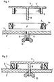
- the devices shown by way of example in FIGS. 1, 7 and 9 allow the manufacture of parts provided with a thread by applying successive layers of polymerizable resins, reinforced with glass fibers, on the reference face 1 of a mold. 2. These devices allow stratification of the part and its threading simultaneously.
- the devices comprise, first of all, an elastomer ring 3, based on silicone, having a thickness adapted to give it good rigidity.
- This crown of diameter and height combined with the dimensions of the thread to be produced, has a side face bearing the imprint of this thread.
- the device shown in Figure 1 allows the manufacture of parts with a female thread.
- the threaded lateral face of the crown 3 is, therefore, its external face 4a.
- the second member of this device is constituted by a crown-holder mandrel 5 around which the crown 3 is positioned.
- the purpose of this mandrel 5 is, on the one hand, to prohibit any deformation of this crown 3 during the operation. molding and, on the other hand, ensuring that it is maintained on the reference face 1 of the mold 2.
- the mandrel 5 is fixed to the mold 2 by a positioning shank 8 extending under the circular plate 7, on the cylindrical part side 6, and provided with a threaded free end.
- This positioning shank 8 is housed in a slot 9 formed in the reference face of the mold 1. The actual blocking is then simply ensured by a nut 1 0-washer 11 assembly.
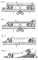
- Figures 2 to 6 illustrate the different operations allowing the molding of a threaded piece 12.
- the crown assembly 3-crown holder mandrel 5 is locked on the reference face 1 of the mold 2 after application of gel -coat on this face ( Figure 2).
- the stratification of the part and its threading is then carried out simultaneously, without first requiring an application of gel-coat in the threads of the crown 3 (FIG. 3).
- the crown-holder mandrel 5 is released from the mold 2 (FIG. 5), then the part 12 is removed from the mold in a conventional manner.
- the last operation then consists in recovering the crown 3 in elastomer, by extracting it from the thread produced, under the effect of its own elasticity (FIG. 6).
- This device therefore makes it possible to produce female threads of large diameters, of determined heights and in the chosen pitch system.
- the only necessary adaptations relate to the crown 3 and the crown-holder mandrel 5, the mold 2 having, for its part, to undergo no modification, except the holes 9 serving for the passage of the positioning tail 8.
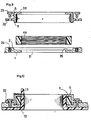
- the device shown in Figure 7 also allows the manufacture of parts with a female thread.
- This device comprises, as before, a crown 3 and a crown-holder mandrel 5. Only the means for fixing this mandrel 5 to the mold 2 differ from those described above.
- These fixing means comprise, in fact, a suction cup 14 fixed under the circular plate 7, on the cylindrical section side 6, so as to come to be applied on the reference face 1 of the mold 2.
- This suction cup 14 is also removably fixed under the circular plate 7. It comprises, for this purpose, a threaded rod 15 which is received in a slot 16 formed in this circular plate 7. The actual blocking is then simply ensured by a nut 17-washer assembly 18. Furthermore, before the suction cup 14 is blocked under the circular plate, a hollow sleeve 19 is engaged on the threaded rod 15 of the latter. During blocking, the circular plate 7 therefore abuts against the sleeve 19 and not against the suction cup 14, thus avoiding possible detachment of the latter.
- the same suction cup 14 the length of the threaded rod 15 of which is sufficient, can be used for different thread heights.
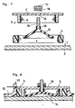
- the third device shown in Figure 9, allows the manufacture of parts with a male thread.
- the threaded lateral face of the crown 3 is therefore its internal face 4b.
- the crown-holder mandrel 5 comprises a cylindrical section 6 of internal diameter combined with the external diameter of the crown 3, and of the same height as the latter.
- This cylindrical section 6 is surmounted by an internal circular ring 20 arranged so as to cover the crown 3 disposed inside the mandrel 5.
- the cylindrical section 6 therefore prohibits radial deformations of the crown 3, while the 'circular ring 20 keeps the front faces of the latter clamped between the reference face 1 of the mold 2 and said ring.
- This crown-holder mandrel 5 is disposed on the side of the reference face 1 of the mold 2 opposite the surface for applying the resin layers. To allow the application of the resin on the threaded lateral face 4b of the crown 3, this reference face has a circular opening 21 of diameter at least equal to the diameter separating the top of the threads from the male thread to be produced.
- fixing lugs 22 extending orthogonally relative to the external face of the cylindrical section 6 and adapted to come to be applied on the reference face 1.
- These fixing lugs 22 are fixed to the reference face 1 by any known screwing means, such as screws 23 which are housed in inserts 24 integrated in this reference face.
- a pre-positioning of the mandrel 5 can be ensured by providing a notch 25 on the periphery of the circular opening 21 of the reference face 1, this notch 25 being of a diameter combined with the external diameter of the cylindrical section 6.
- the molding of the threaded part 12 (FIG. 10) and its demolding are then carried out in the same way as for a part provided with a female thread: positioning then fixing on the mold 2 of the 5-crown mandrel assembly 3 , application of the resin layers, cutting of the burrs 13 beyond the circular ring 20, disassembly of the mandrel 5, extraction of the crown 3, and finally, demolding of the part 12 by removing its threaded part through the opening 21 of the reference face 1 of the mold 2.
- the demolding operation requires that all the male threads of the part 12 be made on the same reference face 1. It is however possible to make threads on different reference faces of the mold, using a removable mold, provided that the axes of these threads are oriented in the direction of disassembly of the faces of the mold concerned.
Landscapes
- Engineering & Computer Science (AREA)
- Mechanical Engineering (AREA)
- Moulds For Moulding Plastics Or The Like (AREA)
- Moulding By Coating Moulds (AREA)
- Casting Or Compression Moulding Of Plastics Or The Like (AREA)
Claims (14)
Applications Claiming Priority (2)
| Application Number | Priority Date | Filing Date | Title |
|---|---|---|---|
| FR8617927A FR2608499B1 (fr) | 1986-12-18 | 1986-12-18 | Procede et dispositif de fabrication de pieces dotees d'un filetage male ou femelle, par moulage notamment d'un materiau polymerisable |
| FR8617927 | 1986-12-18 |
Publications (2)
| Publication Number | Publication Date |
|---|---|
| EP0274792A1 EP0274792A1 (de) | 1988-07-20 |
| EP0274792B1 true EP0274792B1 (de) | 1990-03-21 |
Family
ID=9342146
Family Applications (1)
| Application Number | Title | Priority Date | Filing Date |
|---|---|---|---|
| EP19870202511 Expired - Lifetime EP0274792B1 (de) | 1986-12-18 | 1987-12-15 | Verfahren und Vorrichtung zum Herstellen von mit Aussen- oder Innengewinde versehenen Gegenständen durch Aufbringen von Schichten aus Faserverstärktem, polymerisierbarem Kunststoff auf Bezugsflächen einer Form |
Country Status (4)
| Country | Link |
|---|---|
| EP (1) | EP0274792B1 (de) |
| DE (1) | DE3761953D1 (de) |
| ES (1) | ES2013759B3 (de) |
| FR (1) | FR2608499B1 (de) |
Family Cites Families (12)
| Publication number | Priority date | Publication date | Assignee | Title |
|---|---|---|---|---|
| FR841369A (fr) * | 1938-01-20 | 1939-05-17 | Comm App Marchal Soc D Expl | Ventouse de fixation |
| GB558672A (en) * | 1941-08-13 | 1944-01-14 | Gen Motors Corp | Improved method and apparatus for moulding powdered material |
| US2751237A (en) * | 1952-11-10 | 1956-06-19 | Edwin E Conley | Hollow fiber reinforced resin products such as pipe fittings with molded internal threads and method of making same |
| GB766523A (en) * | 1954-04-26 | 1957-01-23 | Bunder Glas G M B H | Improvements in or relating to a method and device for the production of seamless stoppers having sealing rings or ribs |
| CH455252A (de) * | 1967-04-21 | 1968-06-28 | Fischer Ag Georg | Spritzgussform zur Herstellung von Kunststoffteilen mit hinterschnittenem Innen-Profil |
| GB1299404A (en) * | 1970-03-19 | 1972-12-13 | L T H Electronics Ltd | Improved method of manufacturing a liquid conductivity cell |
| GB1405411A (en) * | 1971-08-14 | 1975-09-10 | Rumble Z K | Apparauts for moulding articles |
| FR2161306A5 (de) * | 1971-11-22 | 1973-07-06 | Kervazo Pierre | |
| US3813197A (en) * | 1972-05-30 | 1974-05-28 | Dayco Corp | Apparatus for making an endless power transmission belt |
| GB1537032A (en) * | 1975-03-07 | 1978-12-29 | Paragon Plastics Ltd | Moulding of an article with a grooved bore |
| US4000240A (en) * | 1975-04-17 | 1976-12-28 | Teletype Corporation | Process of molding a reinforced flexible belt |
| DE3237298C1 (de) * | 1982-10-08 | 1983-12-15 | Frömag Fröndenberger Maschinen-u.Apparatebau-Gesellschaft mbH, 5758 Fröndenberg | Vorrichtung zum Entfernen von gespritzten Kunststoffteilen mit Gewinden aus dem Werkzeug einer Spritzgiessmaschine |
-
1986
- 1986-12-18 FR FR8617927A patent/FR2608499B1/fr not_active Expired
-
1987
- 1987-12-15 EP EP19870202511 patent/EP0274792B1/de not_active Expired - Lifetime
- 1987-12-15 DE DE8787202511T patent/DE3761953D1/de not_active Expired - Fee Related
- 1987-12-15 ES ES87202511T patent/ES2013759B3/es not_active Expired - Lifetime
Also Published As
| Publication number | Publication date |
|---|---|
| ES2013759B3 (es) | 1990-06-01 |
| EP0274792A1 (de) | 1988-07-20 |
| FR2608499A1 (fr) | 1988-06-24 |
| DE3761953D1 (de) | 1990-04-26 |
| FR2608499B1 (fr) | 1989-05-05 |
Similar Documents
| Publication | Publication Date | Title |
|---|---|---|
| EP0653293B1 (de) | Reifenform und Verfahren zum Formen eines Reifens | |
| LU86192A1 (fr) | Moule pour bandages pneumatiques | |
| EP2957410A1 (de) | System mit einziehbaren kernen für das formgiessen von teilen | |
| EP0384161B1 (de) | Befestigungsvorrichtung für ein Werkzeug auf den Walzen einer umlaufenden Maschine | |
| EP2072287B1 (de) | Reifen, Form für die Vulkanisierung dieses Reifens, Herstellungsverfahren dieser Form und Matrize der Form | |
| EP3131729B1 (de) | Tandemwerkzeug zum herstellen spritzgegossener kunststoffteile | |
| EP0274792B1 (de) | Verfahren und Vorrichtung zum Herstellen von mit Aussen- oder Innengewinde versehenen Gegenständen durch Aufbringen von Schichten aus Faserverstärktem, polymerisierbarem Kunststoff auf Bezugsflächen einer Form | |
| EP4171916B1 (de) | Vorrichtung zum ausstossen einer form mit einer kette mit gleitgliedern und einem einstellkeil | |
| EP2578376A1 (de) | Optisches Teil mit einem Kern und mehreren Schichten | |
| FR2948894A1 (fr) | Procede de surmoulage, et moule pour sa mise en oeuvre | |
| EP0546885A1 (de) | Zylinder für eine Stranggiessvorrichtung zum Giessen von Metallbändern, entsprechende Stranggiessvorrichtung und Verfahren zur Herstellung eines derartigen Zylinders | |
| EP0976532B1 (de) | Form für Fahrzeugreifen, und geeignete Vulkanisierpresse zum Aufnehmen einer solchen Form | |
| EP0968802B1 (de) | Formwerkzeug und formgebendes Element zum Formen eines Einschnittes in einem Gegenstand aus Gummi | |
| EP1446275B1 (de) | Reifenform | |
| BE1013764A5 (fr) | Objet en matiere plastique, tel qu'une tetine, procede de fabrication de cet objet et moule pour la mise en oeuvre de ce procede. | |
| EP3727795B1 (de) | Halbform mit zylindrischer montagefläche und herstellungsverfahren | |
| FR2733175A1 (fr) | Procede et moule pour le moulage par injection d'une glace de dispositif d'eclairage ou de signalisation de vehicule automobile | |
| FR2707915A1 (fr) | Boîte en matière plastique moulée avec une tubulure, en particulier pour échangeur de chaleur, et procédé de moulage. | |
| EP1762372A1 (de) | Vorrichtung zur Herstellung einer optischen Linse aus synthetischem Kunststoff | |
| FR3124756A1 (fr) | Procédé de fabrication d’un élément de garnissage à double décor et dispositif associé | |
| CA2364909A1 (fr) | Procede et dispositif de formation d'une bonde ainsi que moule de fabrication d'un corps creux equipe d'un tel dispositif | |
| FR2877259A1 (fr) | Dispositif de fabrication par moulage d'une enveloppe a soufflets comprenant un noyau devissable et des moyens de retenue de l'enveloppe, et procede correspondant | |
| EP0673745B1 (de) | Markiervorrichtung mit einem bewegbaren indexierbaren Einsatz für Spritzgiessform | |
| EP1095840B1 (de) | Kraftfahrzeuglenkrad und Verfahren zu seiner Herstellung | |
| FR3162152A1 (fr) | Machine de découpe à l’aide d’un fil diamanté |
Legal Events
| Date | Code | Title | Description |
|---|---|---|---|
| PUAI | Public reference made under article 153(3) epc to a published international application that has entered the european phase |
Free format text: ORIGINAL CODE: 0009012 |
|
| AK | Designated contracting states |
Kind code of ref document: A1 Designated state(s): BE DE ES FR GB GR IT |
|
| 17P | Request for examination filed |
Effective date: 19880917 |
|
| 17Q | First examination report despatched |
Effective date: 19890612 |
|
| GRAA | (expected) grant |
Free format text: ORIGINAL CODE: 0009210 |
|
| AK | Designated contracting states |
Kind code of ref document: B1 Designated state(s): BE DE ES FR GB GR IT |
|
| PG25 | Lapsed in a contracting state [announced via postgrant information from national office to epo] |
Ref country code: IT Free format text: LAPSE BECAUSE OF FAILURE TO SUBMIT A TRANSLATION OF THE DESCRIPTION OR TO PAY THE FEE WITHIN THE PRESCRIBED TIME-LIMIT;WARNING: LAPSES OF ITALIAN PATENTS WITH EFFECTIVE DATE BEFORE 2007 MAY HAVE OCCURRED AT ANY TIME BEFORE 2007. THE CORRECT EFFECTIVE DATE MAY BE DIFFERENT FROM THE ONE RECORDED. Effective date: 19900321 Ref country code: GR Free format text: LAPSE BECAUSE OF FAILURE TO SUBMIT A TRANSLATION OF THE DESCRIPTION OR TO PAY THE FEE WITHIN THE PRESCRIBED TIME-LIMIT Effective date: 19900321 |
|
| REF | Corresponds to: |
Ref document number: 3761953 Country of ref document: DE Date of ref document: 19900426 |
|
| GBT | Gb: translation of ep patent filed (gb section 77(6)(a)/1977) | ||
| PLBE | No opposition filed within time limit |
Free format text: ORIGINAL CODE: 0009261 |
|
| STAA | Information on the status of an ep patent application or granted ep patent |
Free format text: STATUS: NO OPPOSITION FILED WITHIN TIME LIMIT |
|
| 26N | No opposition filed | ||
| REG | Reference to a national code |
Ref country code: GB Ref legal event code: IF02 |
|
| PGFP | Annual fee paid to national office [announced via postgrant information from national office to epo] |
Ref country code: ES Payment date: 20041217 Year of fee payment: 18 |
|
| PGFP | Annual fee paid to national office [announced via postgrant information from national office to epo] |
Ref country code: GB Payment date: 20041221 Year of fee payment: 18 |
|
| PGFP | Annual fee paid to national office [announced via postgrant information from national office to epo] |
Ref country code: BE Payment date: 20041224 Year of fee payment: 18 |
|
| PGFP | Annual fee paid to national office [announced via postgrant information from national office to epo] |
Ref country code: DE Payment date: 20050126 Year of fee payment: 18 |
|
| PG25 | Lapsed in a contracting state [announced via postgrant information from national office to epo] |
Ref country code: GB Free format text: LAPSE BECAUSE OF NON-PAYMENT OF DUE FEES Effective date: 20051215 |
|
| PG25 | Lapsed in a contracting state [announced via postgrant information from national office to epo] |
Ref country code: ES Free format text: LAPSE BECAUSE OF NON-PAYMENT OF DUE FEES Effective date: 20051216 |
|
| PG25 | Lapsed in a contracting state [announced via postgrant information from national office to epo] |
Ref country code: BE Free format text: LAPSE BECAUSE OF NON-PAYMENT OF DUE FEES Effective date: 20051231 |
|
| PG25 | Lapsed in a contracting state [announced via postgrant information from national office to epo] |
Ref country code: DE Free format text: LAPSE BECAUSE OF NON-PAYMENT OF DUE FEES Effective date: 20060701 |
|
| GBPC | Gb: european patent ceased through non-payment of renewal fee |
Effective date: 20051215 |
|
| REG | Reference to a national code |
Ref country code: ES Ref legal event code: FD2A Effective date: 20051216 |
|
| BERE | Be: lapsed |
Owner name: *SOC. NATIONALE DE TRAITEMENT DES EAUX S.A. Effective date: 20051231 |
|
| PGFP | Annual fee paid to national office [announced via postgrant information from national office to epo] |
Ref country code: FR Payment date: 20061222 Year of fee payment: 20 |