EP0274572B1 - Scanner zur optischen Abtastung von Objekten, insbesondere Aufzeichnungsplatten - Google Patents
Scanner zur optischen Abtastung von Objekten, insbesondere Aufzeichnungsplatten Download PDFInfo
- Publication number
- EP0274572B1 EP0274572B1 EP87114302A EP87114302A EP0274572B1 EP 0274572 B1 EP0274572 B1 EP 0274572B1 EP 87114302 A EP87114302 A EP 87114302A EP 87114302 A EP87114302 A EP 87114302A EP 0274572 B1 EP0274572 B1 EP 0274572B1
- Authority
- EP
- European Patent Office
- Prior art keywords
- mirror
- scanning direction
- scanning
- concave mirror
- hsp
- Prior art date
- Legal status (The legal status is an assumption and is not a legal conclusion. Google has not performed a legal analysis and makes no representation as to the accuracy of the status listed.)
- Expired - Lifetime
Links
- 230000003287 optical effect Effects 0.000 title claims abstract description 11
- 230000001427 coherent effect Effects 0.000 claims abstract description 3
- 238000007689 inspection Methods 0.000 claims description 16
- 239000000758 substrate Substances 0.000 claims description 4
- 238000006073 displacement reaction Methods 0.000 claims description 2
- 230000002093 peripheral effect Effects 0.000 claims description 2
- 230000000694 effects Effects 0.000 abstract description 2
- 239000010410 layer Substances 0.000 description 9
- 239000002184 metal Substances 0.000 description 8
- 230000007547 defect Effects 0.000 description 6
- 229920003023 plastic Polymers 0.000 description 6
- 239000000463 material Substances 0.000 description 5
- 230000005855 radiation Effects 0.000 description 5
- 238000001514 detection method Methods 0.000 description 3
- 230000005540 biological transmission Effects 0.000 description 2
- 239000011248 coating agent Substances 0.000 description 2
- 238000000576 coating method Methods 0.000 description 2
- 238000013461 design Methods 0.000 description 2
- 239000004744 fabric Substances 0.000 description 2
- 238000000926 separation method Methods 0.000 description 2
- 230000003595 spectral effect Effects 0.000 description 2
- 230000001154 acute effect Effects 0.000 description 1
- 230000004075 alteration Effects 0.000 description 1
- 230000006866 deterioration Effects 0.000 description 1
- 238000011156 evaluation Methods 0.000 description 1
- 238000003384 imaging method Methods 0.000 description 1
- 238000004519 manufacturing process Methods 0.000 description 1
- 238000005259 measurement Methods 0.000 description 1
- 238000000034 method Methods 0.000 description 1
- 239000011241 protective layer Substances 0.000 description 1
- 230000035945 sensitivity Effects 0.000 description 1
- 238000010998 test method Methods 0.000 description 1
- 238000012360 testing method Methods 0.000 description 1
- 238000013024 troubleshooting Methods 0.000 description 1
Images


Classifications
-
- G—PHYSICS
- G01—MEASURING; TESTING
- G01N—INVESTIGATING OR ANALYSING MATERIALS BY DETERMINING THEIR CHEMICAL OR PHYSICAL PROPERTIES
- G01N21/00—Investigating or analysing materials by the use of optical means, i.e. using sub-millimetre waves, infrared, visible or ultraviolet light
- G01N21/84—Systems specially adapted for particular applications
- G01N21/88—Investigating the presence of flaws or contamination
- G01N21/95—Investigating the presence of flaws or contamination characterised by the material or shape of the object to be examined
- G01N21/9506—Optical discs
-
- G—PHYSICS
- G02—OPTICS
- G02B—OPTICAL ELEMENTS, SYSTEMS OR APPARATUS
- G02B26/00—Optical devices or arrangements for the control of light using movable or deformable optical elements
- G02B26/08—Optical devices or arrangements for the control of light using movable or deformable optical elements for controlling the direction of light
- G02B26/10—Scanning systems
- G02B26/12—Scanning systems using multifaceted mirrors
- G02B26/125—Details of the optical system between the polygonal mirror and the image plane
-
- G—PHYSICS
- G11—INFORMATION STORAGE
- G11B—INFORMATION STORAGE BASED ON RELATIVE MOVEMENT BETWEEN RECORD CARRIER AND TRANSDUCER
- G11B7/00—Recording or reproducing by optical means, e.g. recording using a thermal beam of optical radiation by modifying optical properties or the physical structure, reproducing using an optical beam at lower power by sensing optical properties; Record carriers therefor
- G11B7/24—Record carriers characterised by shape, structure or physical properties, or by the selection of the material
- G11B7/26—Apparatus or processes specially adapted for the manufacture of record carriers
- G11B7/268—Post-production operations, e.g. initialising phase-change recording layers, checking for defects
Definitions
- the invention relates to an optical error inspection device of the type specified in the preamble of claim 1.
- Fault inspection devices of this type with a scanner are used in the production-accompanying testing of CD recording disks (compact discs).
- CD recording disks compact discs
- the latter are metallized plastic disks covered with a transparent protective layer, on which digital information, in particular an audio or video signal, is accommodated in the form of microscopic elevations and depressions.
- the CD recording disks are read out with a laser beam which is reflected on the metal layer.
- a scanner used for the inspection of CD recording disks works on the same principle. This makes it possible to scan the plate surface without gaps with a rapidly deflected laser beam while simultaneously rotating the plate, and to detect plate errors which cause a change in the reflected and / or diffracted laser light.
- the coherent laser light it is known for the coherent laser light to be incident on the CD recording disk parallel to the disk normal, viewed perpendicularly to the scanning direction, but viewed at a small angle to the disk normal.
- the angle serves to separate the incident light and the light reflected back from the plate. It is small, for example approximately 1.5 °, so that due to the separation of incident and reflected light, there is no appreciable enlargement of the light spot above the reflecting metal surface and occurs transversely to the scanning direction, and thus a correspondingly high measurement accuracy and error sensitivity is also achieved for errors above the metal surface - in the substrate or on the readout side.
- the incident laser beam penetrates the approximately 1.2 mm thick plastic layer of the CD recording disc and is reflected by the metallic reflective coating underneath.
- the information pattern of the CD recording disc which acts like a diffraction grating, generates several discrete diffraction orders.
- the reflected light of the zeroth and the discrete higher diffraction orders is reflected several times at the interfaces between air and plastic on the one hand and plastic and reflective coating on the other hand, each laser beam generating discrete diffraction orders again when it hits the information tracks of the CD recording disc.
- each laser beam generating discrete diffraction orders again when it hits the information tracks of the CD recording disc.
- light beam superimpositions occur as interferences of the same thickness. This leads to significant modulations of the received signal of the light coming from the disk, reflected and / or diffracted, which makes the detection of manufacturing errors of the CD recording disk more difficult and the accuracy of the test method is reduced.
- an optical troubleshooting device for tissue in which a mirror wheel is illuminated by a light source in order to generate a scanning light spot that can be displaced along a scanning line on a fabric path.
- the light reflected by the mirror wheel is directed onto the fabric web via a strip-shaped concave mirror.
- a scanning device is known from JP-A 56-155 916, in which a laser light beam is directed via a vibrating mirror, a mirror wheel and a concave mirror onto a projection surface.
- the oscillating mirror changes the direction of the light beam in such a way that the angle of incidence of the light beam is variable perpendicular to the scanning direction.
- the intensity ratio between the reflected and the transmitted beam must be determined in order to determine the spectral transmission of the film material, the intensity fluctuations due to the interference cancel each other out, since these intensity changes in both beams correspond to one another.
- the object of the present invention is to create a new optical error inspection device of the type mentioned at the outset, in particular to make it possible to eliminate interferences which lead to a modulation of the received signal lead to suppress in an effective manner, without significantly impairing the accuracy of error detection.
- the laser beams reflected back and forth between the boundary surfaces of the recording plate are spatially separated. The disturbing interference phenomena thus disappear.
- the angle of incidence ⁇ O enclosed between the surface normal and the projection of the scanning beam onto the plane defined by the scanning direction and the surface normal has an apparent broadening of the scanning light spot in the scanning direction due to the slight spatial separation of the incident and reflected beam, and thus an apparent widening of errors in this Direction, especially for defects near the plate surface.
- This apparent broadening of errors does not play a decisive role in the inspection result.
- a further alternative to the solution according to the invention is to increase the angle, when viewed in the scanning direction unchanged in the normal direction, of the laser beam, which, viewed perpendicular to the scanning direction, includes the angle on the surface of the object to be scanned.
- the laser beams reflected back and forth between the interfaces of the CD recording disc are also spatially separated, so that the interference phenomena disappear.
- a relatively large angle of incidence perpendicular to the scanning direction results in an apparent error lengthening in the track direction for errors within the permeable plastic layer, and in particular errors lying near the plate surface, because the incident and spatially separated reflected beam detects the error one after the other.
- the accuracy of error detection i.e. the error length evaluation is affected.
- the deflection device of the fault inspection device according to the invention can contain a polygonal mirror wheel driven in rotation with peripheral mirror surfaces and a concave mirror which lies in the beam path between the mirror wheel and the object.
- the concave mirror can be designed as a concave mirror strip of a preferably spherical or circular cylindrical concave mirror.
- a telecentric design is possible for the scanner of an error inspection device according to the invention, in which the mirror surface of the mirror wheel hit by the light beam lies at the focal point of the concave mirror.
- the slightly oblique radiation of the laser beam according to the invention in the scanning or scanning direction to achieve the scanner is turned on in the scanning direction relative to the object to be scanned at the desired angle. This can be done by tilting the whole scanner towards the object to be scanned or by tilting this object towards the scanner.
- the telecentric scanner can be misaligned so that the concave mirror is inclined relative to the mirror wheel in the scanning direction at a small angle compared to the telecentric arrangement.
- Another possible misalignment is to move the concave mirror parallel to the mirror wheel in the scanning direction compared to its telecentric arrangement.
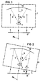
- Fig. 1 shows a telecentric scanner with which an object, in particular a recording disc CD is scanned.
- the scanner has a housing G in which there is a mirror wheel S and a concave mirror Hsp.
- the mirror wheel S which is only drawn in sections, is a polygon mirror which is driven in rotation about its center. Faceted mirror surfaces are provided on the periphery of the mirror wheel S. One of the mirror surfaces is hit by an incident laser beam 10 hit.
- the concave mirror Hsp is arranged in the housing G parallel to the scanning direction. It is designed as a concave mirror strip. is the geometric center of the concave mirror Hsp.
- the effective mirror surface of the mirror wheel S is located at the focal point F of the concave mirror Hsp, ie half the distance between its geometric center and the concave mirror surface.
- the divergent scanning beams 12 reflected by the mirror wheel S are therefore directed in parallel by the concave mirror Hsp. They leave the housing G, the lower edge 14 of which is aligned parallel to the object CD to be scanned, and, viewed in the scanning direction, strike the surface of the object CD perpendicularly. The latter is repeatedly swept linearly by the laser beam when the mirror wheel S rotates.
- CD recording disks Compact Disc
- the telecentric scanner and the object CD to be scanned are inclined relative to one another in the scanning direction.
- the housing G of the scanner is pivoted relative to the recording plate CD so that the lower housing edge 14 forms an acute angle with the surface of the recording plate CD to be scanned.
- the recording disc CD or its holder it is also possible to pivot the recording disc CD or its holder accordingly.
- the internal structure of the scanner has not changed compared to FIG. 1. It can be seen that the laser beams emerging from the housing G now include an angle ⁇ other than zero when viewed in the scanning direction with a normal 16 on the surface to be scanned. The angle ⁇ is small; he is a maximum of approx. 3 °. This slightly oblique radiation of the laser light in the scanning direction prevents interference on thin layers and the associated modulation of the signal obtained during the inspection of CD recording disks.
- the scanner housing is aligned parallel to the object to be scanned, and the scanner is slightly misaligned compared to the telecentric arrangement of FIG. 1.
- the concave mirror Hsp is rotated about an axis P which is oriented parallel to the axis of rotation of the mirror wheel S and is located at the location of the concave mirror surface at which the center beam 18 reflected by the mirror wheel S strikes the concave mirror Hsp.
- the center beam 18 is no longer reflected back in itself, but rather is offset in the scanning direction or counter to the scanning direction.
- the laser beams when viewed in the scanning direction, strike the surface of the object CD to be scanned at an angle unequal to 90 °, and the interferences that can be observed in the vertical incidence disappear.
- the effective mirror surface of the mirror wheel S is not exactly in the focus of the concave mirror Hsp, which leads to small focus errors at the end of the scan area. However, these do not significantly affect the scan result, particularly when inspecting CD recording disks.
- the concave mirror Hsp is laterally displaced in the scanning direction or counter to the scanning direction. This also shifts the geometric center of the concave mirror Hsp from to Since the connecting line between the geometric The center and the beam impact point on the concave mirror forms the bisector between the incident and the emerging beam, the beams are deflected here too so that they strike the object to be scanned at an angle not equal to 90 °. This suppresses the interferences that occur with vertical radiation incidence without noticeable aberrations occurring.
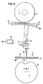
- FIG. 5 and 6 show more details of a telecentric scanner in the basic structure, in which the concave mirror Hsp is pivoted slightly according to the principle illustrated in FIG. 3.
- the scanner contains a laser 20, from which a laser beam emanates and falls on a deflecting mirror 22 via an imaging optics (not shown).
- the direction of incidence is the viewing direction of the observer.
- the deflecting mirror 22 throws the laser beam onto the rapidly rotating mirror wheel S.
- the reflected light reaches the concave mirror Hsp via a further deflecting mirror 23 and from there onto the CD recording disc to be scanned.
- the latter consists of a carrier substrate 24, a metallic reflective layer 26 applied thereon and a cover layer 28 made of transparent plastic.
- the light scattered back from the CD recording plate re-enters the scanner and is thrown onto a suitable detector 30.
- the concave mirror Hsp is pivoted by a small actuating stroke d relative to its position in a telecentric scanner.
- the scanning laser beam includes the desired small angle ⁇ with a normal on the surface of the recording plate to be scanned in the scanning direction.
- the slanted incidence of the scanning laser beam in the scanning direction is thus realized.
- the conventional oblique incidence of the scanning laser beam is also provided transversely to the scanning direction.
- the optical axis of the laser Because of the normal 16, a small angle ⁇ is formed on the surface of the recording plate to be scanned, viewed transversely to the scanning direction, which serves to separate the incident light and the light scattered back from the recording plate.
- the angle ⁇ is achieved by a folded beam path transverse to the scanning direction with a corresponding arrangement of the optical elements.
- the measure of the defect width or defect length of a defect is the time during which the scanning laser beam hits the defect at a given scan frequency (and thus scan speed) and given plate rotation speed.
- the scanning laser beam appears to be larger in an error plane above the metal surface.
- This apparently larger scanning beam now hits a defect above the reflecting metal surface for a long time.
- the finest scanning beam hits an apparently larger error on the metal surface for the same time. This leads to an apparent increase in error, especially for errors that are far away from the reflective metal layer, i.e. for damage to the plate surface (readout side).
Landscapes
- Physics & Mathematics (AREA)
- General Physics & Mathematics (AREA)
- Optics & Photonics (AREA)
- Engineering & Computer Science (AREA)
- Manufacturing & Machinery (AREA)
- Health & Medical Sciences (AREA)
- Life Sciences & Earth Sciences (AREA)
- Chemical & Material Sciences (AREA)
- Analytical Chemistry (AREA)
- Biochemistry (AREA)
- General Health & Medical Sciences (AREA)
- Immunology (AREA)
- Pathology (AREA)
- Investigating Materials By The Use Of Optical Means Adapted For Particular Applications (AREA)
- Mechanical Optical Scanning Systems (AREA)
- Optical Recording Or Reproduction (AREA)
- Optical Radar Systems And Details Thereof (AREA)
- Moving Of The Head For Recording And Reproducing By Optical Means (AREA)
- Length Measuring Devices By Optical Means (AREA)
Description
- Die Erfindung betrifft eine optische Fehlerinspektionsvorrichtung der im Oberbegriff des Patentanspruchs 1 angegebenen Art.
- Derartige Fehlerinspektionsvorrichtungen mit einem Scanner, wie sie aus der EP-A-0 123 929 bekannt sind, werden bei der produktionsbegleitenden Prüfung von CD-Aufzeichnungsplatten (Compact Disc) eingesetzt. Letztere sind mit einer durchsichtigen Schutzschicht überzogene metallisierte Kunststoffscheiben, auf denen eine digitale Information, insbesondere ein Audio- oder Videosignal, in Form mikroskopischer Erhebungen und Vertiefungen untergebracht sind. Zur Wiedergabe werden die CD-Aufzeichnungsplatten mit einem Laserstrahl ausgelesen, der an der Metallschicht reflektiert wird. Nach demselben Prinzip arbeitet ein bei der Inspektion von CD-Aufzeichnungsplatten verwendeter Scanner. Dieser erlaubt es, mit einem schnell abgelenkten Laserstrahl unter gleichzeitiger Rotation der Platte die Plattenoberfläche lückenlos abzutasten und dabei Plattenfehler zu detektieren, die eine Veränderung des reflektierten und/oder gebeugten Laserlichtes hervorrufen.
- Es ist bekannt, das kohärente Laserlicht in Scanrichtung gesehen parallel zur Plattennormalen, senkrecht zur Scanrichtung gesehen aber unter einem kleinen Winkel zur Plattennormalen auf die CD-Aufzeichnungsplatte auffallen zu lassen. Der Winkel dient dabei zur Trennung des einfallenden und des von der Platte zurückreflektierten Lichts. Er ist klein, beispielsweise ca. 1,5°, damit durch die Trennung von einfallendem und reflektiertem Licht keine nennenswerte Vergrößerung des Lichtflecks oberhalb der reflektierenden Metallfläche und quer zur Scanrichtung eintritt, und damit eine entsprechend hohe Meßgenauigkeit und Fehlerempfindlichkeit auch für Fehler oberhalb der Metallfläche - im Substrat oder auf der Ausleseseite erreicht wird. Der einfallende Laserstrahl durchdringt die ca. 1,2 mm dicke Kunststoffschicht der CD-Aufzeichnungsplatte, und er wird von der darunterliegenden metallischen Reflexbeschichtung reflektiert. Dabei erzeugt das Informationsmuster der CD-Aufzeichnungsplatte, welches wie ein Beugungsgitter wirkt, mehrere diskrete Beugungsordnungen. Das reflektierte Licht der nullten und der diskreten höheren Beugungsordnungen wird an den Grenzflächen zwischen Luft und Kunststoff einerseits und Kunststoff und Reflexbeschichtung andererseits mehrfach reflektiert, wobei jeder Laserstrahl beim Wiederauftreffen auf die Informationsspuren der CD-Aufzeichnungsplatte erneut diskrete Beugungsordnungen erzeugt. Auf diese Weise kommt es bei entsprechender Geometrie der Grenzflächen zueinander zu Lichtstrahlüberlagerungen als Interferenzen gleicher Dicke. Das führt zu deutlichen Modulationen des Empfangssignals des von der Platte kommenden, reflektierten und/oder gebeugten Lichtes, wodurch die Detektion von Herstellungsfehlern der CD-Aufzeichnungsplatte erschwert und die Genauigkeit des Prüfverfahrens herabgesetzt wird.
- Aus der EP-A-0 020 880 ist eine optische Fehlersuchvorrichtung für Gewebe bekannt, bei der zur Erzeugung eines entlang einer Abtastlinie auf eine Gewebebahn verschiebbaren Abtastlichtflecks ein Spiegelrad von einer Lichtquelle beleuchtet wird. Das vom Spiegelrad reflektierte Licht wird über einen streifenförmigen Hohlspiegel auf die Gewebebahn gelenkt.
- Aus der JP-A 56-155 916 ist eine Abtasteinrichtung bekannt, bei der ein Laserlichtstrahl über einen Schwingspiegel, ein Spiegelrad und einen Hohlspiegel auf eine Projektionsoberfläche gelenkt wird. Der Schwingspiegel ändert dabei die Richtung des Lichtstrahls in der Weise, daß der Einfallswinkel des Lichtstrahls senkrecht zur Abtastrichtung variabel ist.
- Aus der US-A-3 854 044 ist schließlich eine Vorrichtung zum Messen der spektralen Transmission eines filmartigen Materials bekannt, bei dem ein konvergentes Einfallslichtbündel so auf die Oberfläche des Filmmaterials gelenkt wird, daß sein Mittenstrahl einen WinkelO mit der normalen zur Filmoberfläche einschließt. Dabei weist sowohl der vom Material reflektierte als auch der durch das Material hindurchgegangene Strahl Intensitätsänderungen infolge von Interferenzen auf, die durch Reflektion des Lichts innerhalb des Films erzeugt werden.

- Da zur Bestimmung der spektralen Transmission des Filmmaterials das Intensitätsverhältnis zwischen dem reflektierten und dem transmittierten Strahl bestimmt werden muß, heben sich die Intensitätsschwankungen infolge der Interferenzen gegenseitig auf, da diese Intensitätsänderungen in beiden Strahlen einander entsprechen.
- Die Aufgabe der vorliegenden Erfindung ist es, eine neue optische Fehlerinspektionsvorrichtung der eingangs genannten Art zu schaffen, insbesondere soll es ermöglicht werden, Interferenzen, die zu einer Modulation des Empfangssignals führen, in wirkungsvoller Weise zu unterdrücken, ohne daß dabei die Genauigkeit der Fehlererkennung nennenswert beeinträchtigt wird.
- Erfindungsgemäß wird diese Aufgabe durch die kennzeichnenden Merkmale des Patentanspruchs 1 gelöst.
- Durch die erfindungsgemäß vorgesehene Neigung des Abtastlichtstrahls gegen die Oberflächennormale der Aufzeichnungsplatte werden die zwischen den Grenzflächen der Aufzeichnungsplatte hin und her reflektierten Laserstrahlen räumlich getrennt. Es verschwinden so die störenden Interferenzerscheinungen.
- Der zwischen der Oberflächennormalen und der Projektion des Abtaststrahls auf die durch die Abtastrichtung und die Oberflächennormale definierte Ebene eingeschlossene Einstrahlwinkel ≠ O hat durch die geringfügige, räumliche Trennung von einfallendem und reflektiertem Strahl eine scheinbare Verbreiterung des Abtastlichtflecks in Abtastrichtung, und damit eine scheinbare Fehlerverbreiterung in dieser Richtung zur Folge, insbesondere für Defekte nahe der Plattenoberfläche. Diese scheinbare Fehlerverbreiterung spielt aber für das Inspektionsergebnis keine entscheidende Rolle.
- Auch eine durch den leicht schrägen Lichteinfall in Scanrichtung eventuell verursachte, geringsfügige Defokussierung am Anfang und am Ende des Scan- bzw. Abtastbereichs ist bei der Inspektion einer CD-Aufzeichnungsplatte in der Wirkung vernachlässigbar.
- Es gibt Alternativen zu der erfindungsgemäß vorgeschlagenen Lösung. Beispielsweise ist es denkbar, die chromatische Kohärenz der Lichtquelle zu stören. Dies würde aber das Ersetzen des Lasers durch eine inkohärente Lichtquelle erforderlich machen, was zahlreiche Nachteile, insbesondere eine Verschlechterung der Signalqualität, mit sich bringt. Weiter ist an eine Störung der räumlichen Kohärenz der Lichtquelle zu denken. Damit gehen aber ähnliche Nachteile einher, und zumindest bei den hohen Abtastfrequenzen von ca. 10 MHz (Scanfrequenz ca. 3 kHz), die hier für die Auslesung von Scanner Video-Signalen erforderlich sind, ist dieses Vorgehen nicht praktikabel.
- Eine weitere Alternative zu der erfindungsgemäßen Lösung besteht darin, bei in Scanrichtung gesehen unverändert in Normalenrichtung erfolgender Einstrahlung des Laserstrahls den Winkel zu vergrößern, den dieser quer zur Scanrichtung gesehen mit der Normalen auf die Oberfläche des abzutastenden Objekts einschließt. Bei nur hinreichend großem Winkel, insbesondere bei einem Einstrahlwinkel von mehr als 5°, werden die zwischen den Grenzflächen der CD-Aufzeichnungsplatte hin- und herreflektierten Laserstrahlen ebenfalls räumlich getrennt, so daß die Interferenzerscheinungen verschwinden. Ein relativ großer Einstrahlwinkel senkrecht zur Scanrichtung hat aber für Fehler innerhalb der durchlässigen Kunststoffschicht, und insbesondere nahe der Plattenoberfläche liegende Fehler eine scheinbare Fehlerverlängerung in Spurrichtung zur Folge, weil der einfallende und räumlich getrennte reflektierte Strahl den Fehler nacheinander erfaßt. Die Genauigkeit der Fehlererkennung, d.h. die Fehlerlängenbewertung, wird damit beeinträchtigt.
- Der erfindungsgemäße Vorschlag, den Laserstrahl sowohl quer zur Scanrichtung, als auch in Scanrichtung unter jeweils einem kleinen Winkel zur Normalen auf die Oberfläche des abzutastenden Objekts einfallen zu lassen, ist von den Nachteilen der behandelten Varianten frei. Insbesondere können beide Winkel sehr klein gewählt werden, so daß die sich ergebende scheinbare Fehlervergrößerung keine nennenswerte Rolle spielt.
- Die Ablenkeinrichtung der erfindungsgemäßen Fehlerinspektionsvorrichtung kann ein in Drehung angetriebenes, polygonales Spiegelrad mit peripheren Spiegelflächen sowie einen Hohlspiegel enthalten, der im Strahlengang zwischen dem Spiegelrad und dem Objekt liegt. Der Hohlspiegel kann dabei als Hohlspiegelstreifen eines vorzugsweise sphärischen oder kreiszylindrischen Hohlspiegels ausgebildet sein.
- Für den Scanner einer erfindungsgemäßen Fehlerinspektionsvorrichtung ist eine telezentrische Bauform möglich, bei der die von dem Lichtstrahl getroffene Spiegelfläche des Spiegelrads im Brennpunkt des Hohlspiegels liegt. Um bei einem derartigen telezentrischen Scanner die erfindungsgemäße, leicht schräge Einstrahlung des Laserstrahls in Scan- bzw. Abtastrichtung zu erreichen, stellt man den Scanner insgesamt in Scanrichtung relativ zu dem abzutastenden Objekt unter dem gewünschten Winkel an. Das kann dadurch geschehen, daß man den ganzen Scanner gegenüber dem abzutastenden Objekt, oder dieses Objekt gegenüber dem Scanner verkippt. Ein Vorteil dieser Bauform ist, daß ein herkömmlicher telezentrischer Scanner ohne Änderung seines inneren Aufbaus zum Einsatz kommen kann, und nur eine Änderung seiner Halterung erforderlich ist. Das Erscheinungsbild der Gesamtanordnung ist allerdings ungewohnt.
- In weiteren Varianten der Erfindung wird daher vorgeschlagen, ausgehend von einem telezentrischen Scanner der genannten Art die Relativstellung von Spiegelrad und Hohlspiegel geringfügig zu modifizieren, um die gewünschte leicht schräge Einstrahlung des Laserstrahls in Scanrichtung zu erreichen. Man kann dazu den telezentrischen Scanner so dejustieren, daß der Hohlspiegel, verglichen mit der telezentrischen Anordnung, relativ zum Spiegelrad in Scanrichtung unter einem kleinen Winkel geneigt ist. Eine andere Dejustiermöglichkeit besteht darin, den Hohlspiegel, verglichen mit seiner telezentrischen Anordnung, relativ zum Spiegelrad in Scanrichtung parallel zu verschieben. Beide Varianten lassen sich auch miteinander kombinieren, und es versteht sich, daß es allein auf die optische Relativstellung von Hohlspiegel und Spiegelrad ankommt, so daß man auch mit Änderungen einer dazwischen liegenden Optik ein vergleichbares Ergebnis erreichen kann. Der Vorteil entsprechend baulich veränderter Scanner ist, daß sie von außen genauso aussehen, und sich genauso handhaben lassen, wie herkömmliche telezentrische Scanner, wobei aber störende Interferenzerscheinungen durch schräge Einstrahlung des Lichts in Scanrichtung unterdrückt sind.
- Die Erfindung wird im folgenden anhand von in den Zeichnungen dargestellten Ausführungsbeispielen näher erläutert.
- Schematisch zeigen:
- Fig. 1
- die Scanebene eines Scanners, der einen Laserstrahl in Scanrichtung gesehen senkrecht auf die Oberfläche eines abzutastenden Objekts abstrahlt;
- Fig. 2
- die Scanebene eines telezentrischen Scanners, der verglichen mit Fig. 1 insgesamt relativ zu dem abzutastenden Objekt geneigt ist, so daß der Laserstrahl in Scanrichtung gesehen mit der Oberflächennormalen des abzutastenden Objekts einen Winkel einschließt;
- Fig. 3
- die Scanebene eines Scanners, der ausgehend von der telezentrischen Anordnung durch in Scanrichtung vorgenommenes Verschwenken eines Hohlspiegels dejustiert ist;
- Fig. 4
- die Scanebene eines Scanners, der ausgehend von der telezentrischen Anordnung durch in Scanrichtung erfolgte Parallelverschiebung eines Hohlspiegels dejustiert ist;
- Fig. 5
- einen Scanner entsprechend der Variante der Fig. 3, wobei der Blick auf die Scanebene gerichtet ist;
- Fig. 6
- eine Ansicht des Scanners quer zur Scanrichtung mit Blick in Richtung VI von Fig. 5; Projektionen N nach n in Fig. 5 und 6 lassen jeweils die Scanrichtung erkennen.
- Fig. 1 zeigt einen telezentrischen Scanner, mit dem ein Objekt, insbesondere eine Aufzeichnungsplatte CD abgetastet wird. Der Scanner hat ein Gehäuse G in dem sich ein Spiegelrad S und ein Hohlspiegel Hsp befinden. Das nur abschnittsweise gezeichnete Spiegelrad S ist ein Polygonspiegel, der in Drehung um seinen Mittelpunkt angetrieben ist. Facettenartige Spiegelflächen sind an der Peripherie des Spiegelrads S vorgesehen. Eine der Spiegelflächen wird von einem einfallenden Laserstrahl 10 getroffen.
- Der Hohlspiegel Hsp ist parallel zur Scanrichtung in dem Gehäuse G angeordnet. Er ist als Hohlspiegelstreifen ausgebildet.

ist das geometrische Zentrum des Hohlspiegels Hsp. - Die wirksame Spiegelfläche des Spiegelrads S befindet sich im Brennpunkt F des Hohlspiegels Hsp , d. h. im halben Abstand zwischen dessen geometrischem Zentrum

und der Hohlspiegelfläche. Die vom Spiegelrad S reflektierten divergenten Abtaststrahlen 12 werden daher durch den Hohlspiegel Hsp parallel gerichtet. Sie verlassen das Gehäuse G , dessen Unterkante 14 parallel zu dem abzutastenden Objekt CD ausgerichtet ist, und treffen in Scanrichtung gesehen senkrecht auf die Oberfläche des Objekts CD auf. Letzteres wird so bei Drehung des Spiegelrads S wiederholt linear von dem Laserstrahl überstrichen. Im Fall einer Inspektion von CD-Aufzeichnungsplatten (Compact Disc) treten dabei die vorerwähnten Interferenzen und Modulationen des Empfangs-Videosignals auf. - Dem abzuhelfen, wird nach Fig. 2 vorgeschlagenen den telezentrischen Scanner und das abzutastende Objekt CD relativ zueinander in Scanrichtung zu neigen. In der Abbildung ist dazu das Gehäuse G des Scanners relativ zu der Aufzeichnungsplatte CD verschwenkt, so daß die Gehäuseunterkante 14 mit der abzutastenden Oberfläche der Aufzeichnungsplatte CD einen spitzen Winkel einschließt. Selbstverständlich ist es auch möglich, die Aufzeichnungsplatte CD oder ihre Halterung entsprechend zu verschwenken. Der innere Aufbau des Scanners ist gegenüber Fig. 1 nicht geändert. Man erkennt, daß die aus dem Gehäuse G austretenden Laserstrahlen nunmehr in Scanrichtung gesehen mit einer Normalen 16 auf die abzutastende Oberfläche einen Winkel β ungleich Null einschließen. Der Winkel β ist klein; er beträgt maximal ca. 3°. Durch diese leicht schräge Einstrahlung des Laserlichts in Scanrichtung verhindert man Interferenzen an dünnen Schichten und die damit einhergehenden Modulationen des bei der Inspektion von CD-Aufzeichnungsplatten gewonnenen Signals.
- Bei den Varianten gemäß Fig. 3 und Fig. 4 ist das Scannergehäuse parallel zu dem abzutastenden Objekt ausgerichtet, und der Scanner ist verglichen mit der telezentrischen Anordnung der Fig. 1 jeweils geringfügig dejustiert. In Fig. 3 ist dazu der Hohlspiegel Hsp um eine Achse P gedreht, die parallel zu der Drehachse des Spiegelrades S orientiert ist und sich an der Stelle der Hohlspiegeloberfläche befindet, an der der von dem Spiegelrad S reflektierte Mittenstrahl 18 auf den Hohlspiegel Hsp trifft. Der Mittenstrahl 18 wird dadurch nicht mehr in sich zurückreflektiert, sondern vielmehr in Scanrichtung oder entgegen der Scanrichtung versetzt. Dadurch treffen die Laserstrahlen in Scanrichtung gesehen unter einem Winkel ungleich 90° auf die Oberfläche des abzutastenden Objekts CD auf, und die bei senkrechtem Einfall zu beobachtenden Interferenzen verschwinden. Anders als bei der telezentrischen Anordnung der Fig. 1, liegt die wirksame Spiegelfläche des Spiegelrads S nicht genau im Fokus des Hohlspiegels Hsp , was zu kleinen Fokusfehlern am Ende des Scanbereichs führt. Diese beeinträchtigen aber das Scanergebnis insbesondere bei der Inspektion von CD-Aufzeichnungsplatten nicht nennenswert.
- In Fig. 4 ist ausgehend von der telezentrischen Anordnung der Fig. 1 der Hohlspiegel Hsp in Scanrichtung oder entgegen der Scanrichtung seitlich verschoben. Dadurch verschiebt sich auch das geometrische Zentrum des Hohlspiegels Hsp von

nach
Da die Verbindungslinie zwischen dem geometrischen Zentrum und dem Strahlauftreffpunkt am Hohlspiegel die Winkelhalbierende zwischen einfallendem und ausfallendem Strahl bildet, werden auch hier die Strahlen so abgelenkt, daß sie unter einem Winkel ungleich 90° auf das abzutastende Objekt auftreffen. Damit werden die bei senkrechtem Strahlungseinfall auftretenden Interferenzen unterdrückt, ohne daß merkliche Abbildungsfehler auftreten. - Fig. 5 und 6 zeigen nähere Einzelheiten eines im Grundaufbau telezentrischen Scanners, bei dem nach dem in Fig. 3 illustrierten Prinzip der Hohlspiegel Hsp geringfügig verschwenkt ist. Der Scanner enthält einen Laser 20, von dem ein Laserstrahl ausgeht und über eine nicht näher dargestellte Abbildungsoptik auf einen Umlenkspiegel 22 fällt. In Fig. 6 ist die Einstrahlrichtung die Blickrichtung des Beobachters. Der Umlenkspiegel 22 wirft den Laserstrahl auf das schnell rotierende Spiegelrad S. Das reflektierte Licht gelangt über einen weiteren Umlenkspiegel 23 auf den Hohlspiegel Hsp und von dort auf die abzutastende CD-Aufzeichnungsplatte. Letztere besteht aus einem Trägersubstrat 24, einer darauf aufgebrachten metallischen Reflexschicht 26 und einer Deckschicht 28 aus transparentem Kunststoff. Das von der CD-Aufzeichnungsplatte zurückgestreute Licht tritt wieder in den Scanner ein und wird auf einen geeigneten Detektor 30 geworfen.
- Wie man Fig. 5 entnimmt, ist der Hohlspiegel Hsp gegenüber seiner Position bei einem telezentrischen Scanner um einen kleinen Stellhub d verschwenkt. Hierdurch schließt der scannende Laserstrahl mit einer Normalen auf die abzutastende Oberfläche der Aufzeichnungsplatte in Scanrichtung gesehen den gewünschten kleinen Winkel β ein. Damit ist der erfindungsgemäße Schrägeinfall des scannenden Laserstrahls in Scanrichtung realisiert. Wie man Fig. 6 entnimmt, ist überdies der herkömmliche Schrägeinfall des scannenden Laserstrahls quer zur Scanrichtung vorgesehen. Die optische Achse des Laser strahls schließt mit der Normalen 16 auf die abzutastende Oberfläche der Aufzeichnungsplatte quer zur Scanrichtung gesehen einen kleinen Winkel α ein, der dazu dient, das einfallende Licht und das von der Aufzeichnungsplatte zurückgestreute Licht zu trennen. Der Winkel α wird wie bei einem telezentrischen Scanner durch einen gefalteten Strahlengang quer zur Scanrichtung mit entsprechender Anordnung der optischen Elemente erreicht.
- Das Maß für die Fehlerbreite bzw. Fehlerlänge eines Defekts ist bei gegebener Scanfrequenz (und damit Scangeschwindigkeit) und gegebener Platten-Rotationsgeschwindigkeit die Zeit, während der der abtastende Laserstrahl den Defekt trifft.
- Wird jetzt durch einen Einfallswinkel ≠ 0° der einfallende und der reflektierte Strahl oberhalb der reflektierenden Metallfläche z.T. räumlich getrennt, so wird der abtastende Laserstrahl in einer Fehlerebene oberhalb der Metallfläche scheinbar größer. Es liegen drei Strahlbereiche vor, nämlich einfallender Strahl, Überlappung von einfallendem und reflektiertem Strahl, reflektierter Strahl. Dieser scheinbar größere Abtaststrahl trifft nun einen Defekt oberhalb der reflektierenden Metallfläche längere Zeit. Für das Inspektionssystem ist das genauso, als wenn der feinste Abtaststrahl auf der Metallfläche für dieselbe Zeit einen scheinbar größeren Fehler trifft. Das führt zu einer scheinbaren Fehlervergrößerung besonders für Fehler, die weit von der reflektierenden Metallschicht entfernt sind, also etwa für Beschädigungen auf der Plattenoberfläche (Ausleseseite).
-
- 10 -
- einfallender Laserstrahl
- 12 -
- divergenter Strahl
- 14 -
- Unterkante
- 16 -
- Normale
- 18 -
- Mittenstrahl
- 20 -
- Laser
- 22 -
- Umlenkspiegel
- 23 -
- Umlenkspiegel
- 24 -
- Trägersubstrat
- 26 -
- metallische Reflexschicht
- 28 -
- Deckschicht
- 30 -
- Detektor
Claims (6)
- Optische Fehlerinspektionsvorrichtung mit einer in einer Halterung befindlichen zu untersuchenden Aufzeichnungsplatte (CD), insbesondere Kompaktdisk, wobei die Aufzeichnungsplatte (CD) in ihrer Ebene rotieren kann, und mit einem Scanner zur optischen Abtastung der Aufzeichnungsplatte, der eine kohärente Lichtquelle und eine Ablenkeinrichtung (S, Hsp) aufweist, die einen von der Lichtquelle erzeugten Abtastlichtstrahl parallel zu sich selbst verschiebt und ihn in einer im wesentlichen linearen Abtastbewegung über die Aufzeichnungsplattenoberfläche streichen läßt, wobei die Projektion des Abtastlichtstrahls auf eine Ebene senkrecht zur Abtastrichtung mit der Oberflächennormalen (16) einen kleinen Winkel α einschließt und mit einem Detektor (30) zur Erfassung von Licht, das von der Aufzeichnungsplatte (CD) zurückgeworfen wird,
dadurch gekennzeichnet,
daß der Abtastlichtstrahl auch in Abtastrichtung geneigt ist, so daß seine Projektion auf die durch die Abtastrichtung und die Oberflächennormale (16) definierte Ebene mit der Oberflächennormalen (16) einen kleinen Winkel β ungleich 0° und kleiner 3° einschließt, so daß Interferenzen, die zwischen den beiden reflektierenden Grenzflächen des Trägersubstrats (24), nämlich zwischen der metallischen Reflexschicht (26) und der Plattenoberfläche der Aufzeichnungsplatte entstehen und zu einer Modulation des Empfangssignals führen, in wirkungsvoller Weise unterdrückt werden. - Fehlerinspektionsvorrichtung nach Anspruch 1,
dadurch gekennzeichnet,
daß die Ablenkeinrichtung ein in Drehung angetriebenes, polygonales Spiegelrad (S) mit peripheren Spiegelflächen sowie einen Hohlspiegel (Hsp) enthält, der im Strahlengang zwischen dem Spiegelrad (S) und der Aufzeichnungsplatte (CD) liegt. - Fehlerinspektionsvorrichtung nach Anspruch 2,
dadurch gekennzeichnet,
daß der Hohlspiegel (Hsp) als Hohlspiegelstreifen eines sphärischen oder kreiszylindrischen Hohlspiegels ausgebildet ist. - Fehlerinspektionsvorrichtung nach einem der Ansprüche 1 bis 3,
dadurch gekennzeichnet,
daß die wirksame Spiegelfläche des Spiegelrads (S) im Brennpunkt (F) des Hohlspiegels (Hsp) liegt, und daß der Scanner insgesamt in Abtastrichtung relativ zum Objekt (CD) unter dem Winkel β angestellt ist. - Fehlerinspektionsvorrichtung nach einem der Ansprüche 1 bis 3,
dadurch gekennzeichnet,
daß der Hohlspiegel (Hsp) in Abtastrichtung geneigt ist. - Fehlerinspektionsvorrichtung nach einem der Ansprüche 1 bis 3,
dadurch gekennzeichnet,
daß der Hohlspiegel (Hsp) relativ zum Spiegelrad (S) in Abtastrichtung parallel verschoben ist.
Priority Applications (1)
| Application Number | Priority Date | Filing Date | Title |
|---|---|---|---|
| AT87114302T ATE88273T1 (de) | 1987-01-12 | 1987-09-30 | Scanner zur optischen abtastung von objekten, insbesondere aufzeichnungsplatten. |
Applications Claiming Priority (2)
| Application Number | Priority Date | Filing Date | Title |
|---|---|---|---|
| DE8700520U | 1987-01-12 | ||
| DE8700520U DE8700520U1 (de) | 1987-01-12 | 1987-01-12 | Scanner zur optischen Abtastung von Objekten, insbesondere Aufzeichnungsplatten |
Publications (3)
| Publication Number | Publication Date |
|---|---|
| EP0274572A2 EP0274572A2 (de) | 1988-07-20 |
| EP0274572A3 EP0274572A3 (en) | 1990-01-31 |
| EP0274572B1 true EP0274572B1 (de) | 1993-04-14 |
Family
ID=6803572
Family Applications (1)
| Application Number | Title | Priority Date | Filing Date |
|---|---|---|---|
| EP87114302A Expired - Lifetime EP0274572B1 (de) | 1987-01-12 | 1987-09-30 | Scanner zur optischen Abtastung von Objekten, insbesondere Aufzeichnungsplatten |
Country Status (5)
| Country | Link |
|---|---|
| US (1) | US4848864A (de) |
| EP (1) | EP0274572B1 (de) |
| JP (1) | JPS63187214A (de) |
| AT (1) | ATE88273T1 (de) |
| DE (2) | DE8700520U1 (de) |
Families Citing this family (16)
| Publication number | Priority date | Publication date | Assignee | Title |
|---|---|---|---|---|
| DE3800053A1 (de) * | 1988-01-04 | 1989-07-13 | Sick Optik Elektronik Erwin | Optische fehlerinspektionsvorrichtung |
| US4984858A (en) * | 1988-02-04 | 1991-01-15 | Minolta Camera Kabushiki Kaisha | Light beam scanning optical system |
| AU598418B2 (en) * | 1988-06-04 | 1990-06-21 | Fujitsu Limited | Optical system for detecting three-dimensional shape |
| US4921320A (en) * | 1988-09-22 | 1990-05-01 | Eastman Kodak Company | Optical scanner |
| DE3923788C1 (de) * | 1989-07-18 | 1991-01-10 | Erwin Sick Gmbh Optik-Elektronik, 8000 Muenchen, De | |
| JPH0364726A (ja) * | 1989-08-02 | 1991-03-20 | Minolta Camera Co Ltd | 光ビーム走査光学系 |
| JPH0364727A (ja) * | 1989-08-02 | 1991-03-20 | Minolta Camera Co Ltd | 光ビーム走査光学系 |
| KR920004442B1 (ko) * | 1989-12-08 | 1992-06-05 | 삼성전자 주식회사 | 광학 정보 기록 및 재생시스템 |
| NL9001253A (nl) * | 1990-06-01 | 1992-01-02 | Philips Nv | Inrichting voor het optisch bepalen van de positie en stand van een voorwerp en optisch inschrijf- en/of weergaveapparaat voorzien van een dergelijke inrichting. |
| NL9001260A (nl) * | 1990-06-01 | 1992-01-02 | Philips Nv | Aftastinrichting met een roteerbare spiegel, alsmede aandrijfeenheid ten gebruike in de aftastinrichting, en rotorlichaam ten gebruike in de aandrijfeenheid. |
| US5168386A (en) * | 1990-10-22 | 1992-12-01 | Tencor Instruments | Flat field telecentric scanner |
| CA2079620A1 (en) * | 1991-10-25 | 1993-04-26 | Roeland M. T. Hekker | Holographic elements for an optical recording system |
| DE4434475C2 (de) * | 1994-09-27 | 1998-05-28 | Basler Gmbh | Verfahren und Vorrichtung zur Qualitätskontrolle eines Gegenstandes, insbesondere einer Compact-Disc |
| US5622268A (en) * | 1994-11-30 | 1997-04-22 | Heidelberg Finishing Systems, Inc. | Apparatus for calipering a collated assemblage |
| US5726748A (en) * | 1996-07-24 | 1998-03-10 | General Electric Company | Optical disc cloud analyzer |
| DE19731545C1 (de) * | 1997-07-23 | 1999-05-27 | Basler Gmbh | Vorrichtung und Verfahren zum optischen Erfassen der Verformung einer Fläche |
Citations (1)
| Publication number | Priority date | Publication date | Assignee | Title |
|---|---|---|---|---|
| EP0123929A2 (de) * | 1983-04-22 | 1984-11-07 | Erwin Sick GmbH Optik-Elektronik | Fehlerfeststellungsvorrichtung |
Family Cites Families (6)
| Publication number | Priority date | Publication date | Assignee | Title |
|---|---|---|---|---|
| GB1382081A (en) * | 1972-03-14 | 1975-01-29 | Ici Ltd | Transmission spectra |
| US4199219A (en) * | 1977-04-22 | 1980-04-22 | Canon Kabushiki Kaisha | Device for scanning an object with a light beam |
| DE2904435C3 (de) * | 1979-02-06 | 1981-11-12 | Erwin Sick Gmbh Optik-Elektronik, 7808 Waldkirch | Lochsuchgerät für Materialbahnen |
| DE2925734C3 (de) * | 1979-06-26 | 1982-06-24 | Erwin Sick Gmbh Optik-Elektronik, 7808 Waldkirch | Optisches Fehlersuchgerät für Materialbahnen |
| DE3212437A1 (de) * | 1982-04-02 | 1983-10-13 | Erwin Sick Gmbh Optik-Elektronik, 7808 Waldkirch | Verfahren zur ermittlung von laenglichen fehlern in bahnmaterial mit optischen mitteln |
| SE456194B (sv) * | 1983-01-31 | 1988-09-12 | Semyre Electronics Ab | Avsokningsanordning |
-
1987
- 1987-01-12 DE DE8700520U patent/DE8700520U1/de not_active Expired
- 1987-09-30 EP EP87114302A patent/EP0274572B1/de not_active Expired - Lifetime
- 1987-09-30 AT AT87114302T patent/ATE88273T1/de active
- 1987-09-30 DE DE8787114302T patent/DE3785435D1/de not_active Expired - Fee Related
- 1987-11-25 US US07/125,301 patent/US4848864A/en not_active Expired - Fee Related
-
1988
- 1988-01-12 JP JP63004638A patent/JPS63187214A/ja active Pending
Patent Citations (1)
| Publication number | Priority date | Publication date | Assignee | Title |
|---|---|---|---|---|
| EP0123929A2 (de) * | 1983-04-22 | 1984-11-07 | Erwin Sick GmbH Optik-Elektronik | Fehlerfeststellungsvorrichtung |
Also Published As
| Publication number | Publication date |
|---|---|
| JPS63187214A (ja) | 1988-08-02 |
| EP0274572A3 (en) | 1990-01-31 |
| US4848864A (en) | 1989-07-18 |
| DE3785435D1 (de) | 1993-05-19 |
| EP0274572A2 (de) | 1988-07-20 |
| DE8700520U1 (de) | 1987-03-12 |
| ATE88273T1 (de) | 1993-04-15 |
Similar Documents
| Publication | Publication Date | Title |
|---|---|---|
| DE3626724C2 (de) | Anordnung zur Oberflächenprüfung | |
| DE3309584C2 (de) | ||
| EP0274572A2 (de) | Scanner zur optischen Abtastung von Objekten, insbesondere Aufzeichnungsplatten | |
| EP0390825B1 (de) | Vorrichtung zum optischen abtasten der oberfläche eines objektes | |
| DE3737631C1 (de) | Optische Abstastvorrichtung fuer ebene Oberflaechen | |
| DE69719427T2 (de) | Optische Vorrichtung zur schnellen Defektanalyse | |
| DE2211049B2 (de) | Vorrichtung zum auslesen eines plattenfoermigen informationstraegers, der in optischer form kodierte bild- und/oder tonsignale enthaelt | |
| WO2000058713A2 (de) | Gerät zur schnellen messung winkelabhängiger beugungseffekte an feinstrukturierten oberflächen | |
| EP0069061B1 (de) | Verfahren und Vorrichtung zum Überprüfen von Bahnmaterial | |
| DE69431152T2 (de) | Interferometrisches flughöhenmessgerät | |
| DE2937427C2 (de) | ||
| DE3873809T2 (de) | Fokusdetektor. | |
| DE19731545C1 (de) | Vorrichtung und Verfahren zum optischen Erfassen der Verformung einer Fläche | |
| EP3807619B1 (de) | Lochscheibe zum selektieren von licht für eine optische abbildung | |
| DE3048132C2 (de) | Automatisches Linsenmeßgerät | |
| EP0218151B1 (de) | Messverfahren und Vorrichtung zur berührungslosen Durchmesserbestimmung dünner Drähte | |
| WO2026087178A1 (de) | Verfahren und vorrichtung zum auslesen von in wafern eingeschriebenen identifizierungsinformationen | |
| DE4434475C2 (de) | Verfahren und Vorrichtung zur Qualitätskontrolle eines Gegenstandes, insbesondere einer Compact-Disc | |
| DE2917932C2 (de) | Vorrichtung zur punktweisen Abtastung einer Informationsstruktur | |
| DE4138679C1 (de) | ||
| DE4033912A1 (de) | Optischer sensor | |
| WO2009124569A1 (de) | Optisches kohärenztomographiesystem und optisches kohärenztomographieverfahren | |
| DE69711808T2 (de) | Vorrichtung zur Aufnahme oder Wiedergabe und Verfahren zur Erkennung des Fokussierungszustandes | |
| DE2628836A1 (de) | Optischer phasendiskriminator | |
| DE3151158A1 (de) | Optisches informationslesegeraet |
Legal Events
| Date | Code | Title | Description |
|---|---|---|---|
| PUAI | Public reference made under article 153(3) epc to a published international application that has entered the european phase |
Free format text: ORIGINAL CODE: 0009012 |
|
| 17P | Request for examination filed |
Effective date: 19870930 |
|
| AK | Designated contracting states |
Kind code of ref document: A2 Designated state(s): AT BE CH DE ES FR GB IT LI NL SE |
|
| PUAL | Search report despatched |
Free format text: ORIGINAL CODE: 0009013 |
|
| AK | Designated contracting states |
Kind code of ref document: A3 Designated state(s): AT BE CH DE ES FR GB IT LI NL SE |
|
| 17Q | First examination report despatched |
Effective date: 19910715 |
|
| GRAA | (expected) grant |
Free format text: ORIGINAL CODE: 0009210 |
|
| AK | Designated contracting states |
Kind code of ref document: B1 Designated state(s): AT BE CH DE ES FR GB IT LI NL SE |
|
| PG25 | Lapsed in a contracting state [announced via postgrant information from national office to epo] |
Ref country code: SE Effective date: 19930414 Ref country code: NL Effective date: 19930414 Ref country code: BE Effective date: 19930414 |
|
| REF | Corresponds to: |
Ref document number: 88273 Country of ref document: AT Date of ref document: 19930415 Kind code of ref document: T |
|
| ITF | It: translation for a ep patent filed | ||
| REF | Corresponds to: |
Ref document number: 3785435 Country of ref document: DE Date of ref document: 19930519 |
|
| ET | Fr: translation filed | ||
| GBT | Gb: translation of ep patent filed (gb section 77(6)(a)/1977) |
Effective date: 19930524 |
|
| PG25 | Lapsed in a contracting state [announced via postgrant information from national office to epo] |
Ref country code: ES Free format text: LAPSE BECAUSE OF FAILURE TO SUBMIT A TRANSLATION OF THE DESCRIPTION OR TO PAY THE FEE WITHIN THE PRESCRIBED TIME-LIMIT Effective date: 19930725 |
|
| PGFP | Annual fee paid to national office [announced via postgrant information from national office to epo] |
Ref country code: GB Payment date: 19930913 Year of fee payment: 7 |
|
| NLV1 | Nl: lapsed or annulled due to failure to fulfill the requirements of art. 29p and 29m of the patents act | ||
| PGFP | Annual fee paid to national office [announced via postgrant information from national office to epo] |
Ref country code: FR Payment date: 19930916 Year of fee payment: 7 |
|
| PG25 | Lapsed in a contracting state [announced via postgrant information from national office to epo] |
Ref country code: LI Effective date: 19930930 Ref country code: CH Effective date: 19930930 Ref country code: AT Effective date: 19930930 |
|
| PGFP | Annual fee paid to national office [announced via postgrant information from national office to epo] |
Ref country code: DE Payment date: 19931111 Year of fee payment: 7 |
|
| PLBE | No opposition filed within time limit |
Free format text: ORIGINAL CODE: 0009261 |
|
| STAA | Information on the status of an ep patent application or granted ep patent |
Free format text: STATUS: NO OPPOSITION FILED WITHIN TIME LIMIT |
|
| 26N | No opposition filed | ||
| REG | Reference to a national code |
Ref country code: CH Ref legal event code: PL |
|
| PG25 | Lapsed in a contracting state [announced via postgrant information from national office to epo] |
Ref country code: GB Effective date: 19940930 |
|
| GBPC | Gb: european patent ceased through non-payment of renewal fee |
Effective date: 19940930 |
|
| PG25 | Lapsed in a contracting state [announced via postgrant information from national office to epo] |
Ref country code: FR Effective date: 19950531 |
|
| PG25 | Lapsed in a contracting state [announced via postgrant information from national office to epo] |
Ref country code: DE Effective date: 19950601 |
|
| REG | Reference to a national code |
Ref country code: FR Ref legal event code: ST |
|
| PG25 | Lapsed in a contracting state [announced via postgrant information from national office to epo] |
Ref country code: IT Free format text: LAPSE BECAUSE OF NON-PAYMENT OF DUE FEES;WARNING: LAPSES OF ITALIAN PATENTS WITH EFFECTIVE DATE BEFORE 2007 MAY HAVE OCCURRED AT ANY TIME BEFORE 2007. THE CORRECT EFFECTIVE DATE MAY BE DIFFERENT FROM THE ONE RECORDED. Effective date: 20050930 |