EP0274094B1 - Zementfreie Endoprothese - Google Patents
Zementfreie Endoprothese Download PDFInfo
- Publication number
- EP0274094B1 EP0274094B1 EP87118668A EP87118668A EP0274094B1 EP 0274094 B1 EP0274094 B1 EP 0274094B1 EP 87118668 A EP87118668 A EP 87118668A EP 87118668 A EP87118668 A EP 87118668A EP 0274094 B1 EP0274094 B1 EP 0274094B1
- Authority
- EP
- European Patent Office
- Prior art keywords
- shaft
- screw spindle
- endoprosthesis according
- window opening
- bridge
- Prior art date
- Legal status (The legal status is an assumption and is not a legal conclusion. Google has not performed a legal analysis and makes no representation as to the accuracy of the status listed.)
- Expired - Lifetime
Links
- 210000000988 bone and bone Anatomy 0.000 claims description 21
- IHQKEDIOMGYHEB-UHFFFAOYSA-M sodium dimethylarsinate Chemical class [Na+].C[As](C)([O-])=O IHQKEDIOMGYHEB-UHFFFAOYSA-M 0.000 claims description 9
- 210000004394 hip joint Anatomy 0.000 claims description 3
- 210000002414 leg Anatomy 0.000 description 10
- 210000000689 upper leg Anatomy 0.000 description 3
- 238000005452 bending Methods 0.000 description 2
- 230000001054 cortical effect Effects 0.000 description 2
- 238000010079 rubber tapping Methods 0.000 description 2
- 206010003694 Atrophy Diseases 0.000 description 1
- 230000006978 adaptation Effects 0.000 description 1
- 238000004873 anchoring Methods 0.000 description 1
- 230000037444 atrophy Effects 0.000 description 1
- 230000004323 axial length Effects 0.000 description 1
- 238000010276 construction Methods 0.000 description 1
- 230000007423 decrease Effects 0.000 description 1
- 239000000126 substance Substances 0.000 description 1
- 210000001694 thigh bone Anatomy 0.000 description 1
- 230000036346 tooth eruption Effects 0.000 description 1
- 230000003313 weakening effect Effects 0.000 description 1
Images
Classifications
-
- A—HUMAN NECESSITIES
- A61—MEDICAL OR VETERINARY SCIENCE; HYGIENE
- A61F—FILTERS IMPLANTABLE INTO BLOOD VESSELS; PROSTHESES; DEVICES PROVIDING PATENCY TO, OR PREVENTING COLLAPSING OF, TUBULAR STRUCTURES OF THE BODY, e.g. STENTS; ORTHOPAEDIC, NURSING OR CONTRACEPTIVE DEVICES; FOMENTATION; TREATMENT OR PROTECTION OF EYES OR EARS; BANDAGES, DRESSINGS OR ABSORBENT PADS; FIRST-AID KITS
- A61F2/00—Filters implantable into blood vessels; Prostheses, i.e. artificial substitutes or replacements for parts of the body; Appliances for connecting them with the body; Devices providing patency to, or preventing collapsing of, tubular structures of the body, e.g. stents
- A61F2/02—Prostheses implantable into the body
- A61F2/30—Joints
- A61F2/32—Joints for the hip
- A61F2/36—Femoral heads ; Femoral endoprostheses
- A61F2/3662—Femoral shafts
- A61F2/367—Proximal or metaphyseal parts of shafts
-
- A—HUMAN NECESSITIES
- A61—MEDICAL OR VETERINARY SCIENCE; HYGIENE
- A61F—FILTERS IMPLANTABLE INTO BLOOD VESSELS; PROSTHESES; DEVICES PROVIDING PATENCY TO, OR PREVENTING COLLAPSING OF, TUBULAR STRUCTURES OF THE BODY, e.g. STENTS; ORTHOPAEDIC, NURSING OR CONTRACEPTIVE DEVICES; FOMENTATION; TREATMENT OR PROTECTION OF EYES OR EARS; BANDAGES, DRESSINGS OR ABSORBENT PADS; FIRST-AID KITS
- A61F2/00—Filters implantable into blood vessels; Prostheses, i.e. artificial substitutes or replacements for parts of the body; Appliances for connecting them with the body; Devices providing patency to, or preventing collapsing of, tubular structures of the body, e.g. stents
- A61F2/02—Prostheses implantable into the body
- A61F2/30—Joints
- A61F2002/30001—Additional features of subject-matter classified in A61F2/28, A61F2/30 and subgroups thereof
- A61F2002/30316—The prosthesis having different structural features at different locations within the same prosthesis; Connections between prosthetic parts; Special structural features of bone or joint prostheses not otherwise provided for
- A61F2002/30329—Connections or couplings between prosthetic parts, e.g. between modular parts; Connecting elements
- A61F2002/30405—Connections or couplings between prosthetic parts, e.g. between modular parts; Connecting elements made by screwing complementary threads machined on the parts themselves
-
- A—HUMAN NECESSITIES
- A61—MEDICAL OR VETERINARY SCIENCE; HYGIENE
- A61F—FILTERS IMPLANTABLE INTO BLOOD VESSELS; PROSTHESES; DEVICES PROVIDING PATENCY TO, OR PREVENTING COLLAPSING OF, TUBULAR STRUCTURES OF THE BODY, e.g. STENTS; ORTHOPAEDIC, NURSING OR CONTRACEPTIVE DEVICES; FOMENTATION; TREATMENT OR PROTECTION OF EYES OR EARS; BANDAGES, DRESSINGS OR ABSORBENT PADS; FIRST-AID KITS
- A61F2/00—Filters implantable into blood vessels; Prostheses, i.e. artificial substitutes or replacements for parts of the body; Appliances for connecting them with the body; Devices providing patency to, or preventing collapsing of, tubular structures of the body, e.g. stents
- A61F2/02—Prostheses implantable into the body
- A61F2/30—Joints
- A61F2/30767—Special external or bone-contacting surface, e.g. coating for improving bone ingrowth
- A61F2/30771—Special external or bone-contacting surface, e.g. coating for improving bone ingrowth applied in original prostheses, e.g. holes or grooves
- A61F2002/3085—Special external or bone-contacting surface, e.g. coating for improving bone ingrowth applied in original prostheses, e.g. holes or grooves with a threaded, e.g. self-tapping, bone-engaging surface, e.g. external surface
-
- A—HUMAN NECESSITIES
- A61—MEDICAL OR VETERINARY SCIENCE; HYGIENE
- A61F—FILTERS IMPLANTABLE INTO BLOOD VESSELS; PROSTHESES; DEVICES PROVIDING PATENCY TO, OR PREVENTING COLLAPSING OF, TUBULAR STRUCTURES OF THE BODY, e.g. STENTS; ORTHOPAEDIC, NURSING OR CONTRACEPTIVE DEVICES; FOMENTATION; TREATMENT OR PROTECTION OF EYES OR EARS; BANDAGES, DRESSINGS OR ABSORBENT PADS; FIRST-AID KITS
- A61F2/00—Filters implantable into blood vessels; Prostheses, i.e. artificial substitutes or replacements for parts of the body; Appliances for connecting them with the body; Devices providing patency to, or preventing collapsing of, tubular structures of the body, e.g. stents
- A61F2/02—Prostheses implantable into the body
- A61F2/30—Joints
- A61F2/32—Joints for the hip
- A61F2/36—Femoral heads ; Femoral endoprostheses
- A61F2/3662—Femoral shafts
- A61F2002/3678—Geometrical features
- A61F2002/368—Geometrical features with lateral apertures, bores, holes or openings, e.g. for reducing the mass, for receiving fixation screws or for communicating with the inside of a hollow shaft
-
- A—HUMAN NECESSITIES
- A61—MEDICAL OR VETERINARY SCIENCE; HYGIENE
- A61F—FILTERS IMPLANTABLE INTO BLOOD VESSELS; PROSTHESES; DEVICES PROVIDING PATENCY TO, OR PREVENTING COLLAPSING OF, TUBULAR STRUCTURES OF THE BODY, e.g. STENTS; ORTHOPAEDIC, NURSING OR CONTRACEPTIVE DEVICES; FOMENTATION; TREATMENT OR PROTECTION OF EYES OR EARS; BANDAGES, DRESSINGS OR ABSORBENT PADS; FIRST-AID KITS
- A61F2220/00—Fixations or connections for prostheses classified in groups A61F2/00 - A61F2/26 or A61F2/82 or A61F9/00 or A61F11/00 or subgroups thereof
- A61F2220/0025—Connections or couplings between prosthetic parts, e.g. between modular parts; Connecting elements
Definitions
- the invention relates to a cementless endoprosthesis, in particular for hip joints, with a screw spindle to be screwed into the natural bone canal, the proximal end of which is mechanically connected to a neck for an articulated head provided at an angle to the spindle axis.
- An endoprosthesis of this type is known from FR-A-2 575 383.
- the core of the threaded spindle must transfer the entire load and therefore has the largest possible diameter. Since the bone canal is not straight, but is always ante-curved and often varied, it must be drilled out, which means that the bone is weakened in zones. The screw spindle is inevitably anchored in the weakened bone areas. As a result of the curvature of the bone canal, the thread bridge of the screw spindle does not engage the bone at all along broad zones. An even application of force through the screw spindle into the femur is not possible.
- the screw spindle is empty in this area or, if need be, grabs cancellous bone with its thread bridge.
- the thread bar cuts into the corticalis, which is considerably harder than the cancellous bone, which is why this endoprosthesis essentially supports the distal area. This results in permanent proximal relief with weakening of the load-bearing structures there and ultimately results in an atrophy of the bone structures increasing from proximal to distal as a biomechanical response.
- the prosthesis gradually loosens and eventually fails.
- the thigh bone becomes rigid and its natural vibration behavior is lost.
- the endoprostheses for hip joints which are generally used today use a non-circular shaft which can be inserted axially into the bone canal and which is approximately adapted to the corresponding dimensions of a bone canal in cross-section and with a certain bending in its longitudinal direction (DE-Z- "Mechanics and prosthesis types, Münch.med. Wschr. 118 (1976) No. 22, page 697, Fig. 5.
- These endoprostheses work according to the wedging principle.
- additional ribs are provided, which either run in the longitudinal direction of the shaft or are designed as transverse support ribs. The latter have the disadvantage compared to the former that spongiosa is sheared off when the shaft is hammered in.
- these shaft prostheses are rotationally stable, they also only bear in the distal region in the cortical bone with the disadvantages described above.
- the object of the invention is to provide a new type of endoprosthesis which allows better anchoring in the femur, mainly in the proximal area.
- the shaft no longer needs to be hammered in, but rather only to be used snugly.
- the shaft mainly has a guiding function for the screw spindle. In the distal area, it only supports load transfer. Possibly. the distal end of the shaft can even be shortened to half the length of conventional shafts. Thanks to the wide-area thread bridge of the screw spindle, which cuts into the cancellous bone and also into the corticalis, a positive fit is achieved in the proximal area of the prosthesis.
- the shaft acts as a support frame for the screw spindle, which can be equipped with a small core diameter, which in turn is responsible for the wide-area design of the thread web. Any loss of substance in the bone is avoided since the bone canal no longer needs to be drilled out.
- Claim 2 leads to the advantage that cancellous bone can enter the cavities in the region of the window opening.
- the threaded web is additionally supported at least in the shaft leg leading to the neck.
- Claim 6 allows a one-piece construction of the shaft, the integrated bridge fulfilling several functions. On the one hand it increases the resilience of the shaft and on the other hand it serves to guide the spindle when screwing in. In fact, the spindle is moved exclusively by the bridge on the precisely specified helical path, so that the screwing in can take place almost blindly.
- the preferably self-tapping thread bridge cuts increasingly deeper into the cancellous bone and finally into the cortical bone until the lower end of the core of the screw spindle engages in a form-fitting manner in a blind hole in the shaft. Both ends of the screw spindle are thus securely held on the shaft.
- a bridge with a helical slot of at least 180 °, but preferably a 360 ° circumferential angle creates a mechanical connection between the two shank legs, which withstands all compressive, tensile and bending forces, it is even more remarkable that that this is even achieved in the embodiment according to claim 7, because there are always strands of material above and below the helical slot that connect the two shaft legs together the.
- the bridge therefore only needs to be widened slightly in a bead-like manner with respect to the distal shaft part.
- the feature of claim 10 is used to hold the spindle non-rotatably in the installed position.
- the hole for the anti-rotation element is preferably introduced in such a way that the anti-rotation element engages in a cutting recess on the outer circumference of the thread web of the screw spindle.
- a prosthesis 10 has a shaft 12, the two broad sides 14 of which taper gradually from the proximal end to the distal end.
- the thickness of the shaft 12 measured between the two narrow sides 16 decreases only very slightly towards the distal end.
- a slightly conical neck 17 for an articulated head adjoins the shaft 12 in one piece at the top right (FIG. 1).
- proximal area of the shaft 12 there are two window openings 18, 20 which extend completely through the shaft 12 at right angles to the broad sides 14.
- the web 22 remaining between the two window openings 18, 20 serves to increase the stability.
- Two proximally diverging legs 24, 26 are formed between the narrow sides 16 and the window openings 18, 20 and are connected to one another in one piece by a bridge 28 at the top.
- the bridge 28 is thickened in a bead-like manner by a small amount compared to the broad sides 14 of the shaft 12.
- the leg 26 facing away from the neck 17 is wider on both sides than the remaining part of the shaft 12, whereby an adaptation to the cross-sectional shape of the bone channel is achieved.
- a screw-shaped slot 36 adjoins the bore 30 to the outside, which opens on the top and bottom sides of the bridge 28, projects into the extension regions of the two legs 24, 26 and emerges on the broad sides 14 of the shaft 12. Despite this slot guide, strands of material remain in the bridge 28 that connect the two legs 24, 26, and these strands of material run in one axial half of the shaft 12 above the slot and in the other half below the helical slot 36.
- a screw spindle 38 is screwed into the shaft 12 along the axis 32, which consists of a circular cylindrical core 40 and a wide-area thread web 42 which tapers conically from proximal to distal.
- the taper angle is 20 ° .
- the thread web 42 has an almost constant thickness and a constant pitch of 11 and it is understood that the slot 36 lying on a helical path in the bridge 28 corresponds to these dimensions.
- the largest diameter of the thread web 42 is 32mm and the smallest diameter at the lower end is 13mm.
- the axial length of the screw thread 42 is about 52mm. Strictly speaking, the thickness of the threaded web 42 is not constant, but the two flanks of the threaded web form an angle of approximately 5 ° with one another, so that the threaded web thickens slightly towards the root.
- the screw spindle 38 is screwed through the bridge 28 into the shaft 12, the bore 30 and the screw-shaped slot 36 forcibly guiding the screw spindle 38 on a screw-shaped path from the start.
- the lower section of the threaded web 42 emerges from the bottom of the bridge 28 and, when screwing in further, the screw spindle 38 gradually passes through the upper window opening 18 and then the lower window opening 20 until the lower end of the core 40 of the screw spindle 38 enters a blind hole 44 coaxial with the bore 30.
- the outer edge of the thread web 42 enters into helical grooves 46, which are machined on the inner surfaces of the legs 24, 26. It goes without saying that the bottom groove 46 of the window opening 18 in the region of the stiffening web 22 is followed by a helical slot corresponding to the slot 36, which leads to the upper helical groove in the leg 26 of the window opening 20.
- the core 40 is anchored at both ends in the bore 30 and the blind hole 44 and the upper section of the threaded web 42 fills the screw-shaped slot 36 in the bridge 28 and runs partially parallel to the bridge deck surface.
- the outer edge of the thread web 42 engages in the area of the window openings 18, 20 in the helical grooves 46, as a result of which the wide-area thread web 42 is additionally stabilized.
- the threaded web 42 has a number of undercuts 48 on the outer edge, which are arranged at a circumferential distance of 90 ° . Cutting teeth are formed on these undercuts, which make the thread web 42 self-tapping.
- the hole 50 is arranged exactly so that the locking screw passes through an undercut 48 of the threaded web 42.
- the window openings 18, 20 are basically trapezoidal, the trapezoidal angle corresponding to the taper angle of the threaded web 42.
- the upper and lower boundary surfaces of the window openings 18, 20 run in each of the two axial halves of the shaft 12 approximately parallel to the threaded web 42.
- the grooves 46 in the legs 24, 26 thus each have the same groove depth.
Landscapes
- Health & Medical Sciences (AREA)
- Orthopedic Medicine & Surgery (AREA)
- Cardiology (AREA)
- Oral & Maxillofacial Surgery (AREA)
- Transplantation (AREA)
- Engineering & Computer Science (AREA)
- Biomedical Technology (AREA)
- Heart & Thoracic Surgery (AREA)
- Vascular Medicine (AREA)
- Life Sciences & Earth Sciences (AREA)
- Animal Behavior & Ethology (AREA)
- General Health & Medical Sciences (AREA)
- Public Health (AREA)
- Veterinary Medicine (AREA)
- Prostheses (AREA)
Description
- Die Erfindung betrifft eine zementfreie Endoprothese besonders für Hüftgelenke, mit einer in den natürlichen Knochenkanal einzuschraubenden Schraubspindel, deren proximales Ende mit einem schräg zur Spindelachse vorgesehenen Hals für einen Gelenkkopf mechanisch verbunden ist.
- Eine Endoprothese dieser Art ist aus der FR-A-2 575 383 bekannt. Der Kern der Gewindespindel muß ß die gesamte Last übertragen und hat daher einen möglichst großen Durchmesser. Da der Knochenkanal nicht geradlinig verläuft, sondern immer antekurviert und häufig varisiert ist, muß er aufgebohrt werden.Das bedeutet zonenweise Schwächungen des Knochens. Die Schraubspindel findet zwangsläufig ihre größte Verankerung in den geschwächten Knochenpartien. Infolge der Krümmung des Knochenkanals tritt der Gewindesteg der Schraubspindel längs breitflächiger Zonen mit dem Knochen überhaupt nicht in Eingriff. Eine gleichmäßige Krafteinleitung durch die Schraubspindel in den Femur ist nicht möglich. Da sich der proximale Femuranteil kelchförmig öffnet, steht die Schraubspindel in diesem Bereich leer bzw. faßt mit ihrem Gewindesteg allenfalls Spongiosa. Am distalen Ende schneidet der Gewindesteg in die Corticalis ein, die erheblich härter als die Spongiosa ist, weswegen diese Endoprothese im wesentlichen im distalen Bereich trägt. Daraus resultiert eine permanente proximale Entlastung mit Schwächung der dortigen Lastaufnahmestrukturen und es entsteht letztlich eine von proximal nach distal zunehmende Atrophie der Knochenstrukturen als biomechanische Antwort. Die Prothese lockert sich allmählich und versagt schließlich. Außerdem tritt eine Verstarrung des Oberschenkelknochens ein und sein natürliches Schwingungsverhalten geht verloren. Aufgrund dieser Nachteile und weil jede Rotationsstabilität fehlt, denn die bei der Schrittführung auftretenden Druck- und Rotationskräfte können die Schraubspindel unkontrolliert verdrehen, hat man diese bekannte Endoprothese, die übrigens von Mc Bride schon 1948 publiziert wurde, schon seit langer Zeit verworfen.
- Die heute allgemein verwendeten Endoprothesen für Hüftgelenke verwenden einen axial in den Knochenkanal einschiebbaren unrunden Schaft, der querschnittsmäßig und mit gewisser Biegung in seiner Längsrichtung den entsprechenden Dimensionen eines Knochenkanals etwa angepaßt ist (DE-Z-"Mechanik und Prothesentypen, Münch.med. Wschr. 118 (1976) Nr. 22, Seite 697, Abb. 5). Diese Endoprothesen arbeiten nach dem Verkeilungsprinzip. Im proximalen Bereich sind zusätzliche Rippen vorgesehen, die entweder in Schaftlängsrichtung verlaufen oder als querlaufende Tragrippen ausgebildet sind. Letztere haben gegenüber ersteren noch den Nachteil, daß beim Einschlagen des Schaftes Spongiosa abgeschert wird. Diese Schaftprothesen sind zwar rotationsstabil, tragen jedoch ebenfalls lediglich im distalen Bereich in der Corticalis mit den vorstehend beschriebenen Nachteilen.
- Aufgabe der Erfindung ist es, eine neuartige Endoprothese zu schaffen, die eine bessere Verankerung im Schenkelknochen und zwar hauptsächlich im proximalen Bereich gestattet.
- Diese Aufgabe wird bei einer zementfreien Endoprothese der eingangs genannten Art durch die Merkmale des Kennzeichnungsteils des Patentanspruches 1 gelöst.
- Der Schaft, dessen Konturen prinzipiell denen des bekannten Schaftes entsprechen braucht nicht mehr eingeschlagen sondern lediglich satt eingesetzt zu werden. Der Schaft hat hauptsächlich eine Führungsfunktion für die Schraubspindel. Im distalen Bereich unterstützt er lediglich die Lasteinleitung. Ggf. kann das distale Ende des Schaftes so gar bis auf die Hälfte der Länge bisher üblicher Schäfte gekürzt werden. Dank des sich in die Spongiosa und auch in die Corticalis einschneidenden breitflächigen Gewindesteges der Schraubspindel wird im proximalen Bereich der Prothese ein Formschluß erzielt. Der Schaft wirkt als Tragrahmen für die Schraubspindel, die dadurch mit einem geringen Kerndurchmesser ausgestattet werden kann, der wiederum für die breiflächige Ausbildung des Gewindesteges ursächlich ist. Jeglicher Substanzverlust des Knochens wird vermieden, da der Knochenkanal nicht mehr aufgebohrt zu werden braucht.
- Anspruch 2 führt zu dem Vorteil, daß Spongiosa in die Hohlräume im Bereich der Fensteröffnung eintreten kann.
- Mit dem Merkmal des Anspruchs 3 wird erreicht, daß der Gewindesteg mindestens in dem zum Hals führenden Schaftschenkel zusätzlich abgestützt wird.
- Die Merkmale der Ansprüche 4 und 5 führen zu einer maximal großen Fensteröffnung bei ausreichender Stabilität der verbleibenden Schaftschenkel.
- Anspruch 6 erlaubt eine einstückige Bauweise des Schaftes, wobei die integrierte Brücke mehrere Funktionen erfüllt. Einmal erhöht sie die Belastbarkeit des Schaftes und zum anderen dient sie der Führung der Spindel beim Einschrauben. Tatsächlich wird die Spindel ausschließlich durch die Brücke auf der genau vorgegebenen schraubenförmigen Bahn bewegt, sodaß das Einschrauben beinahe blind erfolgen kann. Der vorzugsweise selbstschneidend ausgebildete Gewindesteg schneidet sich zunehmend tiefer in die Spongiosa und schließlich in die Corticalis ein, bis das untere Ende des Kerns der Schraubspindel in ein Sackloch des Schaftes formschlüssig eingreift. Beide Enden der Schraubspindel sind damit am Schaft sicher gehaltert. Wenn es auch schon überraschend ist, daß eine mit einem schraubenförmigen Schlitz von mindestens 180°, vorzugsweise aber 360° Umfangswinkel versehene Brücke eine mechanische Verbindung zwischen den beiden SchaftschenkeIn herstellt, die allen Druck-, Zug- und Biegekräften standhält, so ist noch bemerkenswerter, daß dies sogar bei der Ausführung gemäß Patentanspruch 7 erreicht wird, denn es verbleiben immer Materialstränge oberhalb und unterhalb des schraubenförmigen Schlitzes, die die beiden Schaftschenkel miteinander verbinden. Die Brücke braucht daher gegenüber dem sich nach distal anschließenden Schaftteil nur geringfügig wulstartig verbreitert zu werden.
- Das Merkmal vom Patentanspruch 10 dient dazu, die Spindel in der Einbaustellung drehsicher festzuhalten. Das Loch für das Drehsicherungselement wird vorzugsweise so eingebracht, daß das Drehsicherungselement in eine Schneidausnehmung am äußeren Umfang des Gewindesteges der Schraubspindel eingreift.
- Anhand der Zeichnung, die ein Ausführungsbeispiel darstellt, sei die Erfindung näher beschrieben.
- Es zeigt
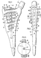
- FIG. 1 eine Seitenansicht der Prothese,
- FIG. 2 eine Frontalansicht der Prothese in Richtung des Halses und
- FIG. 3 eine Querschnittsansicht der Prothese längs der Linie 3-3 der FIG. 2.
- Eine Prothese 10 hat einen Schaft 12, dessen beide Breitseiten 14 sich vom proximalen Ende zum distalen Ende hin allmählich verjüngen. Die zwischen den beiden Schmalseiten 16 gemessene Dicke des Schaftes 12 verringert sich zum distalen Ende nur ganz geringfügig. Oben rechts (FIG.1) schließt sich an den Schaft 12 einstückig ein leicht konischer Hals 17 für einen Gelenkkopf an.
- Im proximalen Bereich des Schaftes 12 befinden sich zwei Fensteröffnungen 18,20, die sich rechtwinklig zu den Breitseiten 14 vollständig durch den Schaft 12 hindurch erstrecken. Der zwischen den beiden Fensteröffnungen 18, 20 verbleibende Steg 22 dient der Stabilitätserhöhung. Zwischen den Schmalseiten 16 und den Fensteröffnungen 18, 20 werden zwei nach proximal divergierende Schenkel 24, 26 gebildet, die oben von einer Brücke 28 miteinander einstückig verbunden sind. Die Brücke 28 ist wulstartig um ein geringes Maß gegenüber den Breitseiten 14 des Schaftes 12 verdickt. Der vom Hals 17 abgewandte Schenkel 26 ist beidseitig breiter als der übrige Teil des Schaftes 12, womit eine Anpassung an die Querschnittsform des Knochenkanals erzielt wird.
- In der Brücke 28 befindet sich eine Bohrung 30, deren Achse 32 mit der Schaftachse 34 einen Winkel a von etwa 5° bildet, derart, daß die Achse 32 gegenüber der Schaftachse 34 zum Hals 17 hin etwas geneigt ist. An die Bohrung 30 schließt sich nach außen ein schraubenförmiger Schlitz 36 an, der an den Deck- und Bodenseiten der Brücke 28 mündet, in die Verlängerungsbereiche der beiden Schenkel 24, 26 hineinragt und an den Breitseiten 14 des Schaftes 12 austritt. Trotz dieser Schlitzführung verbleiben Materialstränge in der Brücke 28, die die beiden Schenkel 24, 26 verbinden und zwar verlaufen diese Materialstränge in der einen Axialhälfte des Schaftes 12 oberhalb des Schlitzes und in der anderen Hälfte unterhalb des schraubenförmigen Schlitzes 36.
- In den Schaft 12 ist eine Schraubspindel 38 längs der Achse 32 eingeschraubt, die aus einem kreiszylindrischen Kern 40 und einem breitflächigen sich von proximal nach distal konisch verjüngenden Gewindesteg 42 besteht. Der Konizitätswinkel beträgt 20°. Der Gewindesteg 42 hat eine fast konstante Dicke und eine konstante Steigung von 11 und es versteht sich, daß der auf schraubenförmigem Bahn liegende Schlitz 36 in der Brücke 28 mit diesen Dimensionen übereinstimmt. Der größte Durchmesser des Gewindesteges 42 beträgt 32mm und der kleinste Durchmesser am unteren Ende ist 13mm groß. Die axiale Länge des Schraubgewindes 42 ist etwa 52mm. Genaugenommen, ist die Dicke des Gewindesteges 42 nicht konstant, sondern die beiden Flanken des Gewindesteges bilden einen Winkel von etwa 5° miteinander, sodaß sich der Gewindesteg zur Wurzel hin geringfügig verdickt.
- Die Schraubspindel 38 wird durch die Brücke 28 hindurch in den Schaft 12 eingeschraubt, wobei die Bohrung 30 und der schraubenförmige Schlitz 36 die Schraubspindel 38 von Anfang an auf einer schraubenförmigen Bahn zwangsweise führen. Nach einer Volldrehung der Schraubspindel 38 tritt der untere Abschnitt des Gewindesteges 42 bodenseitig aus der Brücke 28 aus und beim weiteren Einschrauben durchsetzt die Schraubspindel 38 allmählich zuerst die obere Fensteröffnung 18 und dann die unteres Fensteröffnung 20, bis das untere Ende des Kerns 40 der Schraubspindel 38 in ein zur Bohrung 30 koaxial liegendes Sackloch 44 eintritt. Gleichzeitig tritt der Außenrand des Gewindesteges 42 in schraubenförmige Nuten 46 ein, die an den Innenflächen der Schenkel 24, 26 eingearbeitet sind. Es versteht sich, daß sich an die unterste Nut 46 der Fensteröffnung 18 im Bereich des Versteifungssteges 22 ein schraubenförmiger Schlitz entsprechend dem Schlitz 36 anschließt, der zur oberen schraubenförmigen Nut im Schenkel 26 der Fensteröffnung 20 führt.
- Im voll eingeschraubten Zustand der Schraubspindel 38 ist der Kern 40 beidendig in der Bohrung 30 und dem Sackloch 44 verankert und der obere Abschnitt des Gewindesteges 42 füllt den schraubenförmigen Schlitz 36 in der Brücke 28 aus und verläuft teilweise parallel zur Brückendeckfläche. Der Außenrand des Gewindesteges 42 greift im Bereich der Fensteröffnungen 18,20 in die schraubenförmigen Nuten 46, wodurch der breitflächige Gewindesteg 42 zusätzlich stabilisiert ist. Der Gewindesteg 42 weist am Außenrand eine Anzahl Hinterschneidungen 48 auf, die im Umfangsabstand von 90° angeordnet sind. An diesen Hinterschneidungen werden Schneidzähne gebildet, die den Gewindesteg 42 selbstschneidend machen.
- In der Brücke 28 befindet sich ein Loch 50, in das ein Drehsicherungselement 52 in Form einer Sperrschraube eingeschraubt ist. Das Loch 50 ist genau so angeordnet, daß die Sperrschraube eine Hinterschneidung 48 des Gewindesteges 42 durchsetzt.
- Die Fensteröffnungen 18, 20 sind prinzipiell trapezförmig ausgebildet, wobei der Trapezwinkel dem Konizitätswinkel des Gewindesteges 42 entspricht. Die oberen und unteren Begrenzungsflächen der Fensteröffnungen 18, 20 verlaufen in jeder der beiden Axialhälften des Schaftes 12 etwa parallel zum Gewindesteg 42. Die Nuten 46 in den Schenkeln 24, 26 haben somit jeweils dieselbe Nuttiefe.
Claims (10)
Priority Applications (1)
| Application Number | Priority Date | Filing Date | Title |
|---|---|---|---|
| AT87118668T ATE55889T1 (de) | 1987-01-03 | 1987-12-16 | Zementfreie endoprothese. |
Applications Claiming Priority (4)
| Application Number | Priority Date | Filing Date | Title |
|---|---|---|---|
| DE19873700102 DE3700102A1 (de) | 1987-01-03 | 1987-01-03 | Schaft einer gelenk-endoprothese |
| DE3700102 | 1987-01-03 | ||
| DE19873725387 DE3725387A1 (de) | 1987-01-03 | 1987-07-31 | Schaft einer hueftgelenkprothese |
| DE3725387 | 1987-07-31 |
Publications (2)
| Publication Number | Publication Date |
|---|---|
| EP0274094A1 EP0274094A1 (de) | 1988-07-13 |
| EP0274094B1 true EP0274094B1 (de) | 1990-08-29 |
Family
ID=25851369
Family Applications (1)
| Application Number | Title | Priority Date | Filing Date |
|---|---|---|---|
| EP87118668A Expired - Lifetime EP0274094B1 (de) | 1987-01-03 | 1987-12-16 | Zementfreie Endoprothese |
Country Status (7)
| Country | Link |
|---|---|
| US (1) | US4840633A (de) |
| EP (1) | EP0274094B1 (de) |
| CN (1) | CN1007698B (de) |
| CA (1) | CA1280852C (de) |
| DE (2) | DE3725387A1 (de) |
| ES (1) | ES2017490B3 (de) |
| GR (1) | GR3000960T3 (de) |
Cited By (6)
| Publication number | Priority date | Publication date | Assignee | Title |
|---|---|---|---|---|
| USD840539S1 (en) | 2010-07-06 | 2019-02-12 | Tornier, Inc. | Prosthesis anchor |
| US10213243B2 (en) | 2011-07-19 | 2019-02-26 | Tornier, Inc. | Osteotome extractor |
| US10456264B2 (en) | 2014-01-24 | 2019-10-29 | Tornier, Inc. | Humeral implant anchor system |
| US10463499B2 (en) | 2016-03-25 | 2019-11-05 | Tornier, Inc. | Stemless shoulder implant with fixation components |
| US12023253B2 (en) | 2014-01-24 | 2024-07-02 | Howmedica Osteonics Corp. | Humeral implant anchor system |
| US12109121B2 (en) | 2016-07-28 | 2024-10-08 | Howmedica Osteonics Corp. | Stemless prosthesis anchor component |
Families Citing this family (22)
| Publication number | Priority date | Publication date | Assignee | Title |
|---|---|---|---|---|
| CH675825A5 (de) * | 1988-08-15 | 1990-11-15 | Sulzer Ag | |
| US4904268A (en) * | 1988-09-12 | 1990-02-27 | Alfredo Alvarado | Prosthetic device |
| US5171284A (en) * | 1989-04-25 | 1992-12-15 | Medevelop Ab | Method of inserting an anchoring element within a finger bone |
| US5458638A (en) * | 1989-07-06 | 1995-10-17 | Spine-Tech, Inc. | Non-threaded spinal implant |
| US5895427A (en) * | 1989-07-06 | 1999-04-20 | Sulzer Spine-Tech Inc. | Method for spinal fixation |
| DE4027183A1 (de) * | 1990-08-28 | 1992-03-05 | Baumgart Rainer | Prothese |
| US5211666A (en) * | 1991-04-22 | 1993-05-18 | New York University | Hip joint femoral component endoprosthesis with a lateral load-transferring support surface |
| US5549702A (en) * | 1994-10-25 | 1996-08-27 | Smith & Nephew Richards Inc. | Flexible orthopaedic stem apparatus |
| US5749916A (en) * | 1997-01-21 | 1998-05-12 | Spinal Innovations | Fusion implant |
| FR2800599B1 (fr) * | 1999-11-10 | 2002-03-01 | Herve Arnould | Tige femorale anatomique pour prothese de hanche |
| US6652591B2 (en) | 2000-12-14 | 2003-11-25 | Depuy Orthopaedics, Inc. | Prosthesis with feature aligned to trabeculae |
| US7285121B2 (en) | 2001-11-05 | 2007-10-23 | Warsaw Orthopedic, Inc. | Devices and methods for the correction and treatment of spinal deformities |
| US20090287309A1 (en) | 2007-01-30 | 2009-11-19 | Tornier Sas | Intra-articular joint replacement |
| US9289304B1 (en) | 2013-03-28 | 2016-03-22 | Robert A. Kaufmann | Prosthesis for partial and total joint replacement |
| CN103445885B (zh) * | 2013-07-02 | 2015-05-13 | 刘顺民 | 膨胀固定股骨柄 |
| CN106667625B (zh) * | 2016-08-03 | 2018-06-26 | 张念非 | 人工髋关节类的股骨柄 |
| CA3076502A1 (en) | 2017-09-25 | 2019-03-28 | Tornier, Inc. | Patient specific stemless prosthesis anchor components |
| US11399948B2 (en) | 2017-12-11 | 2022-08-02 | Howmedica Osteonics Corp. | Stemless prosthesis anchor components and kits |
| US10828147B1 (en) | 2018-01-21 | 2020-11-10 | Robert A. Kaufmann | Ligament retention device |
| AU2019352591B2 (en) | 2018-10-02 | 2021-08-12 | Howmedica Osteonics Corp. | Shoulder prosthesis components and assemblies |
| WO2021067497A1 (en) | 2019-10-01 | 2021-04-08 | Tornier, Inc. | Shoulder prosthesis components and assemblies |
| USD951449S1 (en) | 2019-10-01 | 2022-05-10 | Howmedica Osteonics Corp. | Humeral implant |
Family Cites Families (11)
| Publication number | Priority date | Publication date | Assignee | Title |
|---|---|---|---|---|
| US3024785A (en) * | 1959-06-10 | 1962-03-13 | Dobelle Martin | Femoral head prosthesis |
| DE2247560C2 (de) * | 1972-09-28 | 1974-05-09 | Artur Fischer | Hueftgelenkkopfprothese |
| US3848276A (en) * | 1973-05-03 | 1974-11-19 | Y Martinez | Knee implant device |
| FR2295729A1 (fr) * | 1974-12-27 | 1976-07-23 | Mahay Et Cie | Prothese totale de la hanche |
| US4259072A (en) * | 1977-04-04 | 1981-03-31 | Kyoto Ceramic Co., Ltd. | Ceramic endosseous implant |
| DE2834155C3 (de) * | 1978-08-04 | 1981-09-17 | Friedrichsfeld Gmbh, Steinzeug- Und Kunststoffwerke, 6800 Mannheim | Oberschenkelschaft für eine Hüftgelenkendoprothese |
| SU1012903A1 (ru) * | 1980-04-03 | 1983-04-23 | Центральный научно-исследовательский институт травматологии и ортопедии им.Н.Н.Приорова | Искусственный тазобедренный сустав |
| DE3323131A1 (de) * | 1983-06-27 | 1985-01-03 | Waldemar Link (Gmbh & Co), 2000 Hamburg | Endoprothese mit einem im knochen zu verankernden schaft |
| FR2575383B1 (fr) * | 1984-12-27 | 1990-11-30 | Lecestre Pierre | Prothese pour articulation diarthrose |
| FR2576777B1 (fr) * | 1985-01-31 | 1987-03-06 | Rhenter Jean Luc | Prothese totale de hanche a fixation primaire |
| US4681590A (en) * | 1986-06-18 | 1987-07-21 | John Tansey | Femoral stem prosthesis |
-
1987
- 1987-07-31 DE DE19873725387 patent/DE3725387A1/de not_active Withdrawn
- 1987-12-16 ES ES87118668T patent/ES2017490B3/es not_active Expired - Lifetime
- 1987-12-16 EP EP87118668A patent/EP0274094B1/de not_active Expired - Lifetime
- 1987-12-16 DE DE8787118668T patent/DE3764627D1/de not_active Expired - Lifetime
- 1987-12-23 US US07/137,257 patent/US4840633A/en not_active Expired - Lifetime
- 1987-12-31 CA CA000555545A patent/CA1280852C/en not_active Expired - Lifetime
-
1988
- 1988-01-03 CN CN88100130A patent/CN1007698B/zh not_active Expired
-
1990
- 1990-10-19 GR GR90400784T patent/GR3000960T3/el unknown
Cited By (6)
| Publication number | Priority date | Publication date | Assignee | Title |
|---|---|---|---|---|
| USD840539S1 (en) | 2010-07-06 | 2019-02-12 | Tornier, Inc. | Prosthesis anchor |
| US10213243B2 (en) | 2011-07-19 | 2019-02-26 | Tornier, Inc. | Osteotome extractor |
| US10456264B2 (en) | 2014-01-24 | 2019-10-29 | Tornier, Inc. | Humeral implant anchor system |
| US12023253B2 (en) | 2014-01-24 | 2024-07-02 | Howmedica Osteonics Corp. | Humeral implant anchor system |
| US10463499B2 (en) | 2016-03-25 | 2019-11-05 | Tornier, Inc. | Stemless shoulder implant with fixation components |
| US12109121B2 (en) | 2016-07-28 | 2024-10-08 | Howmedica Osteonics Corp. | Stemless prosthesis anchor component |
Also Published As
| Publication number | Publication date |
|---|---|
| ES2017490B3 (es) | 1991-02-16 |
| CN1007698B (zh) | 1990-04-25 |
| GR3000960T3 (en) | 1991-12-10 |
| DE3725387A1 (de) | 1989-02-09 |
| CN88100130A (zh) | 1988-07-13 |
| DE3764627D1 (de) | 1990-10-04 |
| US4840633A (en) | 1989-06-20 |
| EP0274094A1 (de) | 1988-07-13 |
| CA1280852C (en) | 1991-03-05 |
Similar Documents
| Publication | Publication Date | Title |
|---|---|---|
| EP0274094B1 (de) | Zementfreie Endoprothese | |
| EP0474015B1 (de) | Endoprothese | |
| EP1951134B1 (de) | Knochenplatte mit mindestens einer schraube zur winkelstabilen fixation | |
| EP0291632B1 (de) | Kleinknochenplatte, insbesondere für die Versorgung von Frakturen des Schädel- und Gesichtsskeletts oder dergleichen | |
| DE8705920U1 (de) | Bausatz-Schaftprothese mit spreizbarem Schaft | |
| EP0513943A1 (de) | Implantat mit Pressfläche | |
| EP1524948A1 (de) | Dentalimplantat mit verankerungskopf und schraubkörper | |
| CH685324A5 (de) | Prothese mit Kupplungsstück. | |
| EP0292742B1 (de) | Distanzschraube | |
| EP1135616A1 (de) | T-verbindung zweier profilstäbe | |
| EP1850784B1 (de) | Zahnimplantat | |
| EP1712197A1 (de) | Knochenplatte | |
| EP0306709A2 (de) | Markraum-Verriegelungsnagel | |
| DE3715420A1 (de) | Distanzschraube | |
| DE3426947C2 (de) | Oberschenkelteil einer Hüftgelenk-Endoprothese | |
| DE8510531U1 (de) | Implantat | |
| DE29607352U1 (de) | Implantat zur Festlegung einer Sehnenersatzplastik | |
| WO2008075160A1 (de) | Plattenimplantat, insbesondere für die anwendung an einer wirbelsäule, mit einem schraubenverschlusss stem | |
| EP0217034A1 (de) | Geradschaft aus Metall für eine Femurkopfprothese | |
| EP0672396B1 (de) | Femorale Schaftendoprothese | |
| DE19652318C1 (de) | Schraube zur gegenseitigen Befestigung von wenigstens zwei Bauteilen | |
| DE19952918C2 (de) | Endoprothese | |
| DE69410982T2 (de) | Stellbare Vorrichtung, insbesondere für Metallrahmen | |
| DE20018012U1 (de) | Endstopfen zum Anschrauben von Sprossen an Abstandhalterrahmen von insbesondere Isolierglasscheiben | |
| DE3726594C2 (de) |
Legal Events
| Date | Code | Title | Description |
|---|---|---|---|
| PUAI | Public reference made under article 153(3) epc to a published international application that has entered the european phase |
Free format text: ORIGINAL CODE: 0009012 |
|
| AK | Designated contracting states |
Kind code of ref document: A1 Designated state(s): AT BE CH DE ES FR GB GR IT LI LU NL SE |
|
| 17P | Request for examination filed |
Effective date: 19880805 |
|
| 17Q | First examination report despatched |
Effective date: 19900207 |
|
| GRAA | (expected) grant |
Free format text: ORIGINAL CODE: 0009210 |
|
| AK | Designated contracting states |
Kind code of ref document: B1 Designated state(s): AT BE CH DE ES FR GB GR IT LI LU NL SE |
|
| REF | Corresponds to: |
Ref document number: 55889 Country of ref document: AT Date of ref document: 19900915 Kind code of ref document: T |
|
| ITF | It: translation for a ep patent filed | ||
| REF | Corresponds to: |
Ref document number: 3764627 Country of ref document: DE Date of ref document: 19901004 |
|
| GBT | Gb: translation of ep patent filed (gb section 77(6)(a)/1977) | ||
| ET | Fr: translation filed | ||
| REG | Reference to a national code |
Ref country code: GR Ref legal event code: FG4A Free format text: 3000960 |
|
| PLBE | No opposition filed within time limit |
Free format text: ORIGINAL CODE: 0009261 |
|
| STAA | Information on the status of an ep patent application or granted ep patent |
Free format text: STATUS: NO OPPOSITION FILED WITHIN TIME LIMIT |
|
| 26N | No opposition filed | ||
| ITTA | It: last paid annual fee | ||
| EPTA | Lu: last paid annual fee | ||
| EAL | Se: european patent in force in sweden |
Ref document number: 87118668.0 |
|
| REG | Reference to a national code |
Ref country code: GB Ref legal event code: IF02 |
|
| PGFP | Annual fee paid to national office [announced via postgrant information from national office to epo] |
Ref country code: GB Payment date: 20021210 Year of fee payment: 16 |
|
| PGFP | Annual fee paid to national office [announced via postgrant information from national office to epo] |
Ref country code: FR Payment date: 20021217 Year of fee payment: 16 |
|
| PGFP | Annual fee paid to national office [announced via postgrant information from national office to epo] |
Ref country code: CH Payment date: 20021224 Year of fee payment: 16 |
|
| PGFP | Annual fee paid to national office [announced via postgrant information from national office to epo] |
Ref country code: SE Payment date: 20021227 Year of fee payment: 16 |
|
| PGFP | Annual fee paid to national office [announced via postgrant information from national office to epo] |
Ref country code: GR Payment date: 20021230 Year of fee payment: 16 |
|
| PGFP | Annual fee paid to national office [announced via postgrant information from national office to epo] |
Ref country code: AT Payment date: 20021231 Year of fee payment: 16 |
|
| PGFP | Annual fee paid to national office [announced via postgrant information from national office to epo] |
Ref country code: LU Payment date: 20030106 Year of fee payment: 16 |
|
| PGFP | Annual fee paid to national office [announced via postgrant information from national office to epo] |
Ref country code: BE Payment date: 20030107 Year of fee payment: 16 |
|
| PGFP | Annual fee paid to national office [announced via postgrant information from national office to epo] |
Ref country code: DE Payment date: 20030220 Year of fee payment: 16 |
|
| PG25 | Lapsed in a contracting state [announced via postgrant information from national office to epo] |
Ref country code: LU Free format text: LAPSE BECAUSE OF NON-PAYMENT OF DUE FEES Effective date: 20031216 Ref country code: GB Free format text: LAPSE BECAUSE OF NON-PAYMENT OF DUE FEES Effective date: 20031216 Ref country code: AT Free format text: LAPSE BECAUSE OF NON-PAYMENT OF DUE FEES Effective date: 20031216 |
|
| PG25 | Lapsed in a contracting state [announced via postgrant information from national office to epo] |
Ref country code: SE Free format text: LAPSE BECAUSE OF NON-PAYMENT OF DUE FEES Effective date: 20031217 |
|
| PGFP | Annual fee paid to national office [announced via postgrant information from national office to epo] |
Ref country code: NL Payment date: 20031217 Year of fee payment: 17 |
|
| PGFP | Annual fee paid to national office [announced via postgrant information from national office to epo] |
Ref country code: ES Payment date: 20031222 Year of fee payment: 17 |
|
| PG25 | Lapsed in a contracting state [announced via postgrant information from national office to epo] |
Ref country code: LI Free format text: LAPSE BECAUSE OF NON-PAYMENT OF DUE FEES Effective date: 20031231 Ref country code: CH Free format text: LAPSE BECAUSE OF NON-PAYMENT OF DUE FEES Effective date: 20031231 Ref country code: BE Free format text: LAPSE BECAUSE OF NON-PAYMENT OF DUE FEES Effective date: 20031231 |
|
| BERE | Be: lapsed |
Owner name: *GOMBERT GUIDO DR. Effective date: 20031231 Owner name: *KALLABIS MANFRED DR. Effective date: 20031231 |
|
| PG25 | Lapsed in a contracting state [announced via postgrant information from national office to epo] |
Ref country code: DE Free format text: LAPSE BECAUSE OF NON-PAYMENT OF DUE FEES Effective date: 20040701 |
|
| PG25 | Lapsed in a contracting state [announced via postgrant information from national office to epo] |
Ref country code: GR Free format text: LAPSE BECAUSE OF NON-PAYMENT OF DUE FEES Effective date: 20040705 |
|
| EUG | Se: european patent has lapsed | ||
| GBPC | Gb: european patent ceased through non-payment of renewal fee |
Effective date: 20031216 |
|
| REG | Reference to a national code |
Ref country code: CH Ref legal event code: PL |
|
| PG25 | Lapsed in a contracting state [announced via postgrant information from national office to epo] |
Ref country code: FR Free format text: LAPSE BECAUSE OF NON-PAYMENT OF DUE FEES Effective date: 20040831 |
|
| REG | Reference to a national code |
Ref country code: FR Ref legal event code: ST |
|
| PG25 | Lapsed in a contracting state [announced via postgrant information from national office to epo] |
Ref country code: ES Free format text: LAPSE BECAUSE OF NON-PAYMENT OF DUE FEES Effective date: 20041217 |
|
| PG25 | Lapsed in a contracting state [announced via postgrant information from national office to epo] |
Ref country code: NL Free format text: LAPSE BECAUSE OF NON-PAYMENT OF DUE FEES Effective date: 20050701 |
|
| NLV4 | Nl: lapsed or anulled due to non-payment of the annual fee |
Effective date: 20050701 |
|
| PG25 | Lapsed in a contracting state [announced via postgrant information from national office to epo] |
Ref country code: IT Free format text: LAPSE BECAUSE OF NON-PAYMENT OF DUE FEES Effective date: 20051216 |
|
| REG | Reference to a national code |
Ref country code: ES Ref legal event code: FD2A Effective date: 20041217 |