EP0274027B2 - Mehrschneidiges Gewindefräsgerät - Google Patents
Mehrschneidiges Gewindefräsgerät Download PDFInfo
- Publication number
- EP0274027B2 EP0274027B2 EP19870116999 EP87116999A EP0274027B2 EP 0274027 B2 EP0274027 B2 EP 0274027B2 EP 19870116999 EP19870116999 EP 19870116999 EP 87116999 A EP87116999 A EP 87116999A EP 0274027 B2 EP0274027 B2 EP 0274027B2
- Authority
- EP
- European Patent Office
- Prior art keywords
- end plate
- insert
- extending
- end portion
- face area
- Prior art date
- Legal status (The legal status is an assumption and is not a legal conclusion. Google has not performed a legal analysis and makes no representation as to the accuracy of the status listed.)
- Expired - Lifetime
Links
- 238000003801 milling Methods 0.000 title claims description 17
- 238000005520 cutting process Methods 0.000 claims description 29
- 239000011295 pitch Substances 0.000 description 3
- 230000000694 effects Effects 0.000 description 1
- 238000000034 method Methods 0.000 description 1
- 230000002441 reversible effect Effects 0.000 description 1
- UONOETXJSWQNOL-UHFFFAOYSA-N tungsten carbide Chemical compound [W+]#[C-] UONOETXJSWQNOL-UHFFFAOYSA-N 0.000 description 1
Images
Classifications
-
- B—PERFORMING OPERATIONS; TRANSPORTING
- B23—MACHINE TOOLS; METAL-WORKING NOT OTHERWISE PROVIDED FOR
- B23G—THREAD CUTTING; WORKING OF SCREWS, BOLT HEADS, OR NUTS, IN CONJUNCTION THEREWITH
- B23G5/00—Thread-cutting tools; Die-heads
- B23G5/18—Milling cutters
- B23G5/182—Milling cutters combined with other tools
-
- B—PERFORMING OPERATIONS; TRANSPORTING
- B23—MACHINE TOOLS; METAL-WORKING NOT OTHERWISE PROVIDED FOR
- B23G—THREAD CUTTING; WORKING OF SCREWS, BOLT HEADS, OR NUTS, IN CONJUNCTION THEREWITH
- B23G2200/00—Details of threading tools
- B23G2200/10—Threading tools comprising cutting inserts
Definitions
- the present invention relates to apparatus for milling threads using replaceable multiple tooth hard insert means.
- a plurality of inserts are used, each insert providing one thread cutting tooth.
- Thread milling is a known method of producing internal and external threads in a work piece.
- One type of conventional thread milling machine is the universal machine which typically includes a cutter head mounted upon a cross slide for swiveling through an arc of 180 ° in order to produce any helix angle of right-hand or left-hand thread.
- a single thread milling cutter or a multiple thread milling cutter is provided.
- a single thread cutter is used for milling threads having coarse pitches or when the thread length is too great for a multiple thread milling cutter.
- a single thread cutter includes cutting surfaces which extend radially and are spaced about the periphery of the cutter head to provide a single row of cutting surfaces.
- a multiple thread milling cutter can be used for milling threads having finer pitches or when the thread length is not too great.
- a multiple thread cutter includes a series of annular rows of teeth.
- Single and multiple thread milling cutters are more fully explained in pages 46-40 to 46-45 A.S.T.M.E.
- a thread milling apparatus comprising a cutter spindle having two opposed end portions wherein said cutter spindle has a longitudinal axis extending from one end portion to the other end portion.
- a cutter head is attached to one end of said cutter spindle whereas an electro motor is attached to the opposing end of said cutter spindle.
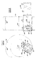
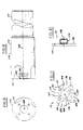
- an apparatus 100 for milling threads comprising a cutter spindle 102 having a first end portion 104 and a second end portion 106.
- Spindle 102 includes a longitudinal axis 108 extending from the first end portion 104 to the second end portion 106.
- Second end portion 106 includes a face area 110 to which is attached an end plate 112.
- Face area 110 lies in a plane which is perpendicular to the longitudinal axis 108.
- End plate 112 also lies in a plane which is perpendicular to the longitudinal axis 108.
- the end plate includes a plurality of insert pockets, four such pockets 114, 116, 118 and 120 being depicted in Figure 11 although more or less are possible.
- each cutting insert includes an aperture 124 extending therethrough from a first insert surface 126 to a second insert surface 128, and a screw 130 extends through aperture 124 into a corresponding threaded aperture 132 which extends into the face area 110.
- Means coupled to the end plate 112 is provided for securing the end plate to the second end portion 106 of the cutter spindle.
- the end plate 112 includes an upper surface 134, a lower surface 136, and a plurality of bores 138 extending therethrough from the upper to the lower surface.
- a plurality of screws 140 is provided, each screw extending through a respective bore 138 into a corresponding threaded bore 142 which extends into face are 110.
- the cutting inserts 122 each include a plurality of sides extending from the first surface 126 to the second surface 128, the first surface being parallel to the second surface, and the first surface engaging face area 110. At least one of the sides comprises a cutting portion although as known in the art the insert can have various cutting portions or edges on more than one side.
- known indexable and reversible hard cutting inserts of tungsten carbide can be used in this embodiment of the present invention.
- each insert pocket 114, 116, 118, 120 is defined by a plurality of insert support side surfaces, two such insert support side surfaces 144 and 146 being depicted for each insert pocket shown in Figure 11, although more insert support side surfaces are possible.
- Surfaces 144 and 146 extend from upper surface 134 to lower surface 136 and preferably intersect the upper and lower surfaces at an angle equal to 90 °.
- the lower surface 136 engages the face area 110. For proper insert alignment, preferably at least two sides of each cutting insert engage respective corresponding insert support side surfaces.
- each insert 122 engage respective corresponding insert support side surfaces 144 and 146 of respective insert pockets 114, 116, 118 and 120.
- the insert support side surfaces 144 and 146 and the face area 110 have a tolerance error equal to about one half of the tolerance error of the threads being produced.
- the end plate 112 is secured to the cutter spindle by means of screws 140. Such securing means prevents movement of the end plate vis-a-vis the cutter spindle.
- the second end portion 106 includes an aperture 152 extending into the cutter spindle from the face area 110 along axis 108.
- End plate 112 includes a corresponding protuberance 154 extending from lower surface 136 along a central axis 156.
- the protuberance 154 extends into the aperture 152 and is secured in place by securing means.
- protuberance 154 includes a bore 158 extending therethrough in a plane perpendicular to axis 156.
- second end portion 106 has a bore 160 extending therethrough.
- a pin 162 is press fit into bores 158 and 160 to hold the end plate in place.
- the cutter spindle 102 is attached to a thread milling machine and caused to rotate in a known manner about its axis 108. Simultaneously, the cutter spindle 102 is rotated in accordance with known circular interpolating principles about the axis 164 of the workpiece 166 being threaded internally at 168 in the embodiment of Figures 6 and 7.
- the total length of the thread being cut is obtained by feeding the workpiece parallel to the axis 108 of the cutter spindle 102 at a feed rate equal to the pitch to be cut. Both internal and external threads can be cut in this manner.
- the cutting surfaces can be replaced merely by replacing one cutting insert with another and discarding the replaced insert.
- Inserts having different thread forms can be provided which in effect provides interchangeability of cutting surfaces for cutting threads having different physical characteristics.
Landscapes
- Engineering & Computer Science (AREA)
- Mechanical Engineering (AREA)
- Milling Processes (AREA)
Claims (10)
dadurch gekennzeichnet,
daß der zweite Endbereich eine Frontfläche (110) aufweist, an welcher eine Abschlußplatte (112) angebracht ist, wobei die Abschlußplatte in einer zu der Längsachse (108) senkrechten Ebene liegt, und die Abschlußplatte eine Vielzahl von sich um die Achse erstreckenden in Umfangsrichtung der Abschlußplatte (112) in Abstand voneinander angeordneten Einsatzaufnahmen (114 - 120) und eine Vielzahl von Schneideinsätzen (122) aufweist, wobei jeder Schneideinsatz der Vielzahl von Schneideinsätzen in einer Einsatzaufnahme der Vielzahl von Einsatzaufnahmen positioniert ist; und daß Einrichtungen (130) zur Halterung der Schneideinsätze in den Einsatzaufnahmen mit den Schneideinsätzen verbunden, und Einrichtungen (152) zur Befestigung der Abschlußplatte an dem zweiten Endbereich der Frässpindel mit der Abschlußplatte verbunden sind.
Applications Claiming Priority (2)
| Application Number | Priority Date | Filing Date | Title |
|---|---|---|---|
| US1117687A | 1987-01-05 | 1987-01-05 | |
| US11176 | 1987-01-05 |
Publications (3)
| Publication Number | Publication Date |
|---|---|
| EP0274027A1 EP0274027A1 (de) | 1988-07-13 |
| EP0274027B1 EP0274027B1 (de) | 1991-10-02 |
| EP0274027B2 true EP0274027B2 (de) | 1994-12-21 |
Family
ID=21749186
Family Applications (1)
| Application Number | Title | Priority Date | Filing Date |
|---|---|---|---|
| EP19870116999 Expired - Lifetime EP0274027B2 (de) | 1987-01-05 | 1987-11-17 | Mehrschneidiges Gewindefräsgerät |
Country Status (3)
| Country | Link |
|---|---|
| EP (1) | EP0274027B2 (de) |
| JP (1) | JPS63251111A (de) |
| DE (2) | DE3773473D1 (de) |
Families Citing this family (4)
| Publication number | Priority date | Publication date | Assignee | Title |
|---|---|---|---|---|
| DE4137467A1 (de) * | 1991-11-14 | 1993-05-19 | Neumo Grundbesitz Gmbh | Profil-schneidwerkzeug, insbesondere gewindefraeser |
| WO1994023874A1 (de) * | 1993-04-14 | 1994-10-27 | Zettl GmbH CNC Präzisions- und Sonderwerkzeuge | Schneidwerkzeug |
| JP2008105144A (ja) * | 2006-10-26 | 2008-05-08 | Toyota Motor Corp | 内径ネジ加工方法 |
| US20180169780A1 (en) * | 2016-12-19 | 2018-06-21 | Anvil International, Llc | Cleanline threader |
Family Cites Families (12)
| Publication number | Priority date | Publication date | Assignee | Title |
|---|---|---|---|---|
| DE1502076C2 (de) * | 1965-05-25 | 1973-11-22 | Kysor Industrial Corp., Cadillac, Mich. (V.St.A.) | Befestigungsmittel für eine Wendechneidplatte an einem Schneidwerkzeug für Metalle |
| DE2151315A1 (de) * | 1971-10-15 | 1973-04-19 | Leitz Ernst Gmbh | Verfahren zum wirbeln mehrgaengiger gewinde |
| IT990237B (it) * | 1972-08-15 | 1975-06-20 | Malinchak P | Perfezionamento negli inserti ta glienti per macchine per la lavora zione di metalli |
| JPS5264086A (en) * | 1975-11-21 | 1977-05-27 | Yuzuru Kusama | Step hole working circular cutter which makes planetary motion |
| DD143740B1 (de) * | 1979-05-23 | 1983-06-15 | Gunter Seipt | Verfahren zum fraesen von innengewinde |
| JPS56141778A (en) * | 1980-04-02 | 1981-11-05 | Toshiba Electric Equip Corp | Inverter |
| US4400117A (en) * | 1981-05-04 | 1983-08-23 | Milling Specialties, Inc. | Insert type milling cutter |
| DD202643A1 (de) * | 1981-07-13 | 1983-09-28 | Smab Forsch Entw Rat | Mehrstufenwirbelvorrichtung zur gleichzeitigen herstellung zylindrischer formelemente einschliesslich gewindeprofile |
| DE3245174A1 (de) * | 1982-12-07 | 1984-06-07 | Herdegen, Siegfried, 3237 Liederbach | Gewindefraes-apparat fuer maschinen mit einem vom werkstueckumlauf abhaengigem verschiebbaren werkzeugtraeger, insbesondere leitspindeldrehbank |
| GB8327581D0 (en) * | 1983-10-14 | 1983-11-16 | Stellram Ltd | Thread cutting |
| JPS60146611A (ja) * | 1984-12-07 | 1985-08-02 | Ebara Corp | 突出座の逃げ面の加工方法 |
| US4648755A (en) * | 1985-07-15 | 1987-03-10 | Gte Valeron Corporation | Multiple insert end mill |
-
1987
- 1987-11-17 EP EP19870116999 patent/EP0274027B2/de not_active Expired - Lifetime
- 1987-11-17 DE DE8787116999T patent/DE3773473D1/de not_active Expired - Lifetime
- 1987-11-17 DE DE1987116999 patent/DE274027T1/de active Pending
-
1988
- 1988-01-05 JP JP16988A patent/JPS63251111A/ja active Pending
Also Published As
| Publication number | Publication date |
|---|---|
| EP0274027B1 (de) | 1991-10-02 |
| DE274027T1 (de) | 1989-01-26 |
| DE3773473D1 (de) | 1991-11-07 |
| JPS63251111A (ja) | 1988-10-18 |
| EP0274027A1 (de) | 1988-07-13 |
Similar Documents
| Publication | Publication Date | Title |
|---|---|---|
| DE69807182T2 (de) | Werkzeugkupplung und methode zum kupplung zweier werkzeugelementen | |
| US5083887A (en) | Helical cutting tool | |
| US6877934B2 (en) | Milling head for thread whirling | |
| DE3610016C2 (de) | ||
| EP0145167B1 (de) | Gewindeschneiden | |
| EP0084223B1 (de) | Verbrauchbarer stufenförmiger Schneideinsatz | |
| EP0964762B1 (de) | Zirkularbohrfräser mit wendeschneidplatten und zugehörigen plattensitzen | |
| EP0796690A2 (de) | Vorrichtung und Verfahren zur Herstellung von hinterschnittenen Nuten | |
| DE102015112417B4 (de) | Rotierendes Schneidwerkzeug mit nachschleifbaren Schneideinsätzen | |
| KR100999912B1 (ko) | 기어 호빙 커터 시스템 | |
| EP0050270B1 (de) | Wälzfräser mit Wendeschneidplatten | |
| EP1764176B1 (de) | Fräswerkzeug | |
| US4531863A (en) | Thread-cutting apparatus | |
| EP0463422B1 (de) | Aufnahme mit einem Dorn für Spanabhebende Maschinenwerkzeuge mit Innenbohrung und Maschinenwerkzeug | |
| US4784537A (en) | Multiple tooth thread milling apparatus | |
| WO1999017899A1 (de) | Schneideinsatz, fräswerkzeug und verwendung des fräswerkzeuges | |
| US4645386A (en) | Thread-cutting apparatus | |
| AT398049B (de) | Werkzeugträger zum wirbeln bzw. schälen von aussengewinden, schnecken und profilen | |
| US2413452A (en) | Cutter | |
| EP0274027B1 (de) | Mehrschneidiges Gewindefräsgerät | |
| DE10230452B4 (de) | Planfräser | |
| DE10144735B4 (de) | Schneideinsätze und Rotations-Umfangsfräser mit austauschbaren Schneideinsätzen | |
| DE3504296C2 (de) | ||
| DE3730943C1 (en) | Parallelogram-shaped indexable insert | |
| DE3707146C1 (en) | Milling tool for making circumferential grooves |
Legal Events
| Date | Code | Title | Description |
|---|---|---|---|
| PUAI | Public reference made under article 153(3) epc to a published international application that has entered the european phase |
Free format text: ORIGINAL CODE: 0009012 |
|
| AK | Designated contracting states |
Kind code of ref document: A1 Designated state(s): DE GB IT SE |
|
| ITCL | It: translation for ep claims filed |
Representative=s name: ZINI MARANESI |
|
| DET | De: translation of patent claims | ||
| 17P | Request for examination filed |
Effective date: 19890111 |
|
| 17Q | First examination report despatched |
Effective date: 19900322 |
|
| GRAA | (expected) grant |
Free format text: ORIGINAL CODE: 0009210 |
|
| AK | Designated contracting states |
Kind code of ref document: B1 Designated state(s): DE GB IT SE |
|
| REF | Corresponds to: |
Ref document number: 3773473 Country of ref document: DE Date of ref document: 19911107 |
|
| ITF | It: translation for a ep patent filed | ||
| PLBI | Opposition filed |
Free format text: ORIGINAL CODE: 0009260 |
|
| 26 | Opposition filed |
Opponent name: STELLRAM LIMITED Effective date: 19920609 |
|
| RAP2 | Party data changed (patent owner data changed or rights of a patent transferred) |
Owner name: VALENITE INC. |
|
| PUAH | Patent maintained in amended form |
Free format text: ORIGINAL CODE: 0009272 |
|
| STAA | Information on the status of an ep patent application or granted ep patent |
Free format text: STATUS: PATENT MAINTAINED AS AMENDED |
|
| 27A | Patent maintained in amended form |
Effective date: 19941221 |
|
| AK | Designated contracting states |
Kind code of ref document: B2 Designated state(s): DE GB IT SE |
|
| EAL | Se: european patent in force in sweden |
Ref document number: 87116999.1 |
|
| ITF | It: translation for a ep patent filed | ||
| PGFP | Annual fee paid to national office [announced via postgrant information from national office to epo] |
Ref country code: GB Payment date: 19951108 Year of fee payment: 9 |
|
| PGFP | Annual fee paid to national office [announced via postgrant information from national office to epo] |
Ref country code: DE Payment date: 19951128 Year of fee payment: 9 |
|
| PG25 | Lapsed in a contracting state [announced via postgrant information from national office to epo] |
Ref country code: GB Effective date: 19961117 |
|
| GBPC | Gb: european patent ceased through non-payment of renewal fee |
Effective date: 19961117 |
|
| PG25 | Lapsed in a contracting state [announced via postgrant information from national office to epo] |
Ref country code: DE Effective date: 19970801 |
|
| PGFP | Annual fee paid to national office [announced via postgrant information from national office to epo] |
Ref country code: SE Payment date: 19971117 Year of fee payment: 11 |
|
| PG25 | Lapsed in a contracting state [announced via postgrant information from national office to epo] |
Ref country code: SE Free format text: LAPSE BECAUSE OF NON-PAYMENT OF DUE FEES Effective date: 19981118 |
|
| EUG | Se: european patent has lapsed |
Ref document number: 87116999.1 |
|
| PG25 | Lapsed in a contracting state [announced via postgrant information from national office to epo] |
Ref country code: IT Free format text: LAPSE BECAUSE OF NON-PAYMENT OF DUE FEES;WARNING: LAPSES OF ITALIAN PATENTS WITH EFFECTIVE DATE BEFORE 2007 MAY HAVE OCCURRED AT ANY TIME BEFORE 2007. THE CORRECT EFFECTIVE DATE MAY BE DIFFERENT FROM THE ONE RECORDED. Effective date: 20051117 |