EP0273970B1 - Multiple range interval clutter cancellation circuit - Google Patents
Multiple range interval clutter cancellation circuit Download PDFInfo
- Publication number
- EP0273970B1 EP0273970B1 EP87904787A EP87904787A EP0273970B1 EP 0273970 B1 EP0273970 B1 EP 0273970B1 EP 87904787 A EP87904787 A EP 87904787A EP 87904787 A EP87904787 A EP 87904787A EP 0273970 B1 EP0273970 B1 EP 0273970B1
- Authority
- EP
- European Patent Office
- Prior art keywords
- canceller
- clutter
- circuit
- processor
- radar
- Prior art date
- Legal status (The legal status is an assumption and is not a legal conclusion. Google has not performed a legal analysis and makes no representation as to the accuracy of the status listed.)
- Expired - Lifetime
Links
Images

Classifications
-
- G—PHYSICS
- G01—MEASURING; TESTING
- G01S—RADIO DIRECTION-FINDING; RADIO NAVIGATION; DETERMINING DISTANCE OR VELOCITY BY USE OF RADIO WAVES; LOCATING OR PRESENCE-DETECTING BY USE OF THE REFLECTION OR RERADIATION OF RADIO WAVES; ANALOGOUS ARRANGEMENTS USING OTHER WAVES
- G01S13/00—Systems using the reflection or reradiation of radio waves, e.g. radar systems; Analogous systems using reflection or reradiation of waves whose nature or wavelength is irrelevant or unspecified
- G01S13/02—Systems using reflection of radio waves, e.g. primary radar systems; Analogous systems
- G01S13/50—Systems of measurement based on relative movement of target
- G01S13/52—Discriminating between fixed and moving objects or between objects moving at different speeds
- G01S13/522—Discriminating between fixed and moving objects or between objects moving at different speeds using transmissions of interrupted pulse modulated waves
- G01S13/524—Discriminating between fixed and moving objects or between objects moving at different speeds using transmissions of interrupted pulse modulated waves based upon the phase or frequency shift resulting from movement of objects, with reference to the transmitted signals, e.g. coherent MTi
- G01S13/53—Discriminating between fixed and moving objects or between objects moving at different speeds using transmissions of interrupted pulse modulated waves based upon the phase or frequency shift resulting from movement of objects, with reference to the transmitted signals, e.g. coherent MTi performing filtering on a single spectral line and associated with one or more range gates with a phase detector or a frequency mixer to extract the Doppler information, e.g. pulse Doppler radar
-
- G—PHYSICS
- G01—MEASURING; TESTING
- G01S—RADIO DIRECTION-FINDING; RADIO NAVIGATION; DETERMINING DISTANCE OR VELOCITY BY USE OF RADIO WAVES; LOCATING OR PRESENCE-DETECTING BY USE OF THE REFLECTION OR RERADIATION OF RADIO WAVES; ANALOGOUS ARRANGEMENTS USING OTHER WAVES
- G01S13/00—Systems using the reflection or reradiation of radio waves, e.g. radar systems; Analogous systems using reflection or reradiation of waves whose nature or wavelength is irrelevant or unspecified
- G01S13/02—Systems using reflection of radio waves, e.g. primary radar systems; Analogous systems
- G01S13/06—Systems determining position data of a target
- G01S13/08—Systems for measuring distance only
- G01S13/10—Systems for measuring distance only using transmission of interrupted, pulse modulated waves
- G01S13/20—Systems for measuring distance only using transmission of interrupted, pulse modulated waves whereby multiple time-around echoes are used or eliminated
-
- G—PHYSICS
- G01—MEASURING; TESTING
- G01S—RADIO DIRECTION-FINDING; RADIO NAVIGATION; DETERMINING DISTANCE OR VELOCITY BY USE OF RADIO WAVES; LOCATING OR PRESENCE-DETECTING BY USE OF THE REFLECTION OR RERADIATION OF RADIO WAVES; ANALOGOUS ARRANGEMENTS USING OTHER WAVES
- G01S13/00—Systems using the reflection or reradiation of radio waves, e.g. radar systems; Analogous systems using reflection or reradiation of waves whose nature or wavelength is irrelevant or unspecified
- G01S13/02—Systems using reflection of radio waves, e.g. primary radar systems; Analogous systems
- G01S13/50—Systems of measurement based on relative movement of target
- G01S13/52—Discriminating between fixed and moving objects or between objects moving at different speeds
- G01S13/522—Discriminating between fixed and moving objects or between objects moving at different speeds using transmissions of interrupted pulse modulated waves
- G01S13/524—Discriminating between fixed and moving objects or between objects moving at different speeds using transmissions of interrupted pulse modulated waves based upon the phase or frequency shift resulting from movement of objects, with reference to the transmitted signals, e.g. coherent MTi
- G01S13/526—Discriminating between fixed and moving objects or between objects moving at different speeds using transmissions of interrupted pulse modulated waves based upon the phase or frequency shift resulting from movement of objects, with reference to the transmitted signals, e.g. coherent MTi performing filtering on the whole spectrum without loss of range information, e.g. using delay line cancellers or comb filters
Definitions
- the present invention relates to Moving Target Indicator (MTI) radar systems employing limited transmitted pulse trains or burst waveforms to form single or multiple filters, and more particularly to a circuit for such radars which cancels returns from ambiguous range clutter with less transmitted energy and less time than that required by conventional systems.
- MMI Moving Target Indicator
- MTI radar systems are well known in the art, and have received considerable discussion in the literature.
- One exemplary general description of MTI radars appears in the book "Introduction to Radar Systems," by Merrill I. Skolnick, McGraw-Hill Book Company, 1980, at Chapter Four. Since the Doppler return from stationary targets have unchanging return amplitudes and range from pulse to pulse, delay-line cancellers are conventionally employed as filters to remove the d-c (unchanging) components of fixed targets and to pass the a-c (changing) components of moving targets.
- the i-f signal from the receiver (or alternatively a baseband inphase and quadrature representation) is divided between two channels, one a normal i-f channel and the other including a delay line providing a delay equivalent to the inter-pulse-period to the i-f signal.
- the outputs from the respective channels are then coherently subtracted from one another, and the resultant signal includes only returns from moving targets, since the returns from fixed targets have non-varying phases and amplitudes from pulse to pulse, and are cancelled.
- This type of processor is known as a single canceller.
- the double canceller employs two cascaded single canceller circuits, which is equivalent to combining the signal from the present pulse period, the signal from the preceding pulse period with its amplitude weighted by -2, and the signal from two pulse periods previous.
- Another configuration is known from the document GB-A-892 282 which discloses a moving target indication radar system, with a target echo cancellation channel in which echo signals resulting from a transmitted pulse are mixed with coherent oscillations phased by the oscillations of the immediately preceding pulse. The outputs from both channels are combined and utilized for MTI display.
- the present invention is concerned with the detection of moving targets by MTI active radars, which process the returns from a plurality of pulses comprising a limited pulse train transmitted at a fixed pulse-repetition-rate (PRF), defining a fixed inter-pulse-period (IPP).
- the length (in time) of the IPP for a given radar is related to the unambiguous range interval, the maximum target range at which a transmitted pulse may propagate to the target and the target return be reflected back to the radar before the next pulse is transmitted.
- the unambiguous range interval may be considered the "first range interval.”
- the target (or a stationary object producing clutter returns) could be at a range which is outside that defined by the unambiguous or first range interval such that the return from the target is received in the second IPP following the transmitted pulse. This second IPP following a particular pulse is considered the "second range interval.” If the target or stationary object is further away from the radar such that the return is received in the third IPP following a transmitted pulse, then the return is considered to be in the "third range interval.”
- the second and third (or further) range intervals are considered to be ambiguous intervals.
- the number of pulses required for MTI operation is a function of the number of returns processed and the number of range intervals over which the processor must be effective in clutter cancellation.
- the number of processed returns determines the frequency response of the canceller, e.g., the breadth of the clutter rejection null formed by the canceller.
- the narrower is the clutter rejection null, centered at zero doppler frequency (stationary object).
- it is desirable to broaden the clutter rejection null e.g., to cancel returns from slowly moving objects not considered "targets,” or to increase the degrees of freedom in tailoring the filter response so as to provide a desired filter characteristic, e.g., sharp filter skirts.
- the returns from more transmitted pulses are processed; e.g., as described above with respect to the single and double cancellers.
- the number of range intervals over which the processor must be effective in clutter rejection also affects the required number of transmitted pulses. Enough pulses must be transmitted to provide the returns required for the processor operation over the number of range intervals over which effective clutter cancellation is required.
- the pulses required to be transmitted to meet the range interval clutter cancellation requirements but which are not used in a given processing interval in the processor are known as "fill" pulses. For example, if four pulses are transmitted and the returns from three pulses are processed in a double canceller MTI radar processor, then one pulse is a fill pulse, and the canceller is capable of cancelling clutter in the first and second range intervals. In a conventional MTI system, enough fill pulses are typically transmitted to assure cancellation of clutter at the longest range.
- the invention comprises an MTI radar detection processor adapted to cancel clutter in the second or further range intervals with fewer fill pulses.
- an MTI processor which employs two (or more) different MTI cancellers.
- the number of pulses transmitted is determined by the number required for the canceller having the broadest clutter cancellation bandwidth (or the greatest number of degrees of freedom in tailoring the clutter rejection response) to cancel clutter from objects within the first range interval.
- the canceller with fewer delay loops has effectively more fill pulses, but also a narrower band clutter rejection bandwidth (or fewer degrees of freedom).
- a logical "AND" function is performed on the outputs of the two (or more) MTI cancellers.
- FIG. 1 illustrates an embodiment of a processor circuit embodying the invention, comprising a first single canceller circuit 11 and a cascaded second single canceller circuit 19.
- the radar return signals 10 from the radar receiver are divided into two channels comprising the first single canceller circuit 12.
- the two channel outputs are weighted and combined at summing device 16.
- One channel includes delay line 12, which provides a time delay equal to the inter-pulse period which is the inverse of the pulse repetition frequency, the "PRF" (1/PRF).
- the delayed channel output is inverted and summed with the non-delayed channel output from line 14.
- the output of summing device 16 at node 18 comprises the single canceller output.
- circuit 19 includes two channels, one including the 1/PRF delay line 20, and the other comprising line 30, and the summing device 24.
- the output of the delay line channel is inverted and combined with the non-delayed channel 22 output by summing device 24.
- the output of the cascaded single canceller 19 appears at node 25.
- This cascaded configuration is conventionally known as a double canceller circuit, and thus the double canceller output is taken at node 25.
- the respective outputs of the single and double cancellers are processed by respective detection and threshold circuits 26 and 31. These circuits test the canceller output against a threshold to provide a target signal indication only when the threshold is crossed. Thus, the output of the circuits 26 and 31 reflect either the "no target detected” condition or the "target detected” condition.
- These circuits are well known to those skilled in the art; one such circuit is described in U.S. Patent No. 4,042,924, by Evan et al. and entitled "MTI Clutter Tracking and Cancelling System.”
- the double canceller has a broader clutter-rejection null in the vicinity of d-c than the single canceller, but requires three transmitted pulses to process over a given range interval to achieve the broader rejection null; i.e., the returns from the current interval and the preceding two intervals are processed to provide the canceller output.
- the single canceller while having a narrower clutter-rejection null than the double canceller, requires only two pulses to process over a given range interval; i.e., the returns from the present interval and the immediately preceding interval are processed to provide the single canceller output.
- the single canceller is capable of cancelling second range interval clutter, while the double canceller is not.
- an additional (fourth) pulse must be transmitted.
- the outputs from the respective threshold circuits 26 and 31 are coupled to the AND gate circuit 32, which performs the logical "AND" function on the respective threshold circuit signals. Only when both threshold circuit outputs indicate a target will the AND gate 32 report a target signal output. Thus, only signals which are processed and provided as a "target detected” output by both cancellers are ultimately detected. Wideband clutter in the early range intervals where the fill pulses are active for both cancellers is rejected, as is narrow band clutter which is within the clutter rejection notch of the single canceller which effectively has more fill pulses. Targets whose doppler return is outside the wide clutter notch are passed by both cancellers and hence continue to be detected.
- FIGS. 2A-2I are pictorial illustrations of the operation of the circuit of FIG. 1 for three transmitted pulses A, B and C.
- the transmitted pulses A, B and C are depicted in FIG. 2A, separated in time by the inter-pulse period which defines the length of the respective time intervals T1-T4 shown in FIG. 2A.
- each interval T1-T4 is 1/PRF seconds in duration.
- the processor of FIG. 1 provides useful output signals only during the time interval T3 following the last transmitted pulse (C). For this example, it is assumed that only clutter returns from stationary targets are received.
- A', B' and C' depict the actual clutter returns (which happen to be from the respective second range intervals in relation to the respective transmitted pulses).
- FIGS. 2C-2E represent the signals processed by the double canceller of FIG. 1.
- FIG. 2D indicates that the apparent first interval return B'' is weighted by a factor of -2, representing the two paths through the circuit of FIG. 1 through only one delay line 12 or 20 (with inversion).
- the apparent first interval return C'' is depicted in FIG. 2E, representing the single undelayed path through the circuit of FIG.
- the summation of the three signals of FIGS. 2C-E represents the summation at device 24, the output of the double canceller, and is non-zero, representing -2B''+C'', shown in FIG. 2F.
- the double canceller output is then processed by the detection and threshold circuit 26, to provide a "high" signal, erroneously representing the "target detected" state.
- the output of the single canceller is represented by the sum of the signals depicted in FIGS. 2G-I.
- the return B'' is shown in FIG. 2G as delayed by 1/PRF and inverted, representing the single delay path through delay line 14 of FIG. 1.
- FIG. 2H represents the return C'' processed through the non-delayed channel of the single canceller.
- the sum of -B'' and C'' provide a zero output of the single canceller, indicated in FIG. 2I.
- the outputs of the respective detection threshold circuits 26 and 31 are coupled to the input of AND gate circuit 32, which performs the conventional AND logic function on the input signals, i.e., the output of the gate 32 will be at the "high” state if and only if both input signals are at the "high” state.
- the "high” state output of the double canceller detection and threshold circuit 26 for this example is “ANDed” with the "low” state output of the single canceller detection and threshold circuit 31 for this example, providing a "low” state processor output, correctly indicating the "no target detected” state. This is the desired result since it was assumed for this example that only stationary clutter is being received, and the object of the circuit is to reject such clutter.
- the advantages of the invention are apparent from comparison with a conventional double canceller MTI radar.
- a conventional double canceller MTI radar In order for such a canceller to be capable of cancelling clutter in the first and second range intervals, four pulses are transmitted and the returns from three pulses are processed by the MTI radar with one pulse being a fill pulse.
- the invention allows the capability of cancelling relatively wideband clutter in the first range interval by the double canceller MTI circuit while utilizing only three transmitted pulses, and while simultaneously cancelling clutter in the first and second range intervals with a single canceller MTI.
- the system depicted in FIG. 1 employs well-known simple MTI canceller circuits, the single canceller and the double canceller.
- MTI cancellers may be generally characterized as comprising one or more transversal filters.
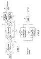
- the filter 50 shown in FIG. 3 is a transversal filter generalization of an MTI filter such as may be formed by the circuits 11 or 19 of FIG. 1.
- the filter 50 comprises n cascaded delay devices 55, each for providing a time delay equal to 1/PRF.
- the various delayed and undelayed signals at the respective taps or nodes 60-63 are weighted by weights W ik and then summed at summing device 65 to provide the filter output.
- the tap weights depicted as W ik are complex and refer to the tap weight for the "ith" tap and the "kth” filter, where i is an integer ranging from zero to n.
- the invention may also be employed with range-gated pulse doppler (RTPD) MTI systems, wherein the time (corresponding to range) between two successive pulses is divided into small time (range) sub-intervals, corresponding to range cells.
- RTPD range-gated pulse doppler
- a number of the filters shown in FIG. 3 are normally employed, with each filter being arranged to pass the radar return signals in a particular doppler region.
- the range cells are examined in succession as the corresponding canceller output signals are generated by the canceller circuit.
- Filters which may contain only clutter returns (i.e., zero doppler frequencies) are typically excluded from the conventional arrangement.
- Each filter has at its output a detector and threshold circuit to detect the presence of a target signal within that filter.
- the outputs of the detector threshold circuits are then processed through a logical "OR" gate function for the purpose of detecting a target.
- This type of arrangement is illustrated in FIG. 4.
- the respective filters 71-74 are coupled to the corresponding detection and threshold circuits 75-78, with the outputs of the circuits 75-78 being coupled to the input of the OR gate 79.
- the circuit enclosed by phantom line 70 may be generally referred to as a clutter canceller comprising a filter set. In order to reject clutter returns, the same clutter signal must appear at all taps of the transversal filter. Therefore, to cancel second range interval clutter in an "n" tap system, n+1 pulses must be transmitted and the return signals from the last n intervals are processed.
- the output of the filters 71-74 will be a time varying signal corresponding to range within the particular doppler filter bandwidth.
- the filter output may be sampled to provide one or more samples within each range cell.
- the samples may be stored in memory for recall for further processing in the event that a target is detected.
- Such further processing could include interpolation between doppler filters to determine the target speed and interpolation of the target return data between range cells to provide an accurate estimate of the target range. Signal amplitudes may also be recovered. Techniques for such further processing are well known to those skilled in the art.
- two sets of filters are employed to process the returns from n transmitted pulses.
- One set of filters is obtained by combining the weighted signals derived from n taps of the general filter illustrated in FIG. 3, and the second set of filters is obtained by combining the weighted signals from the first n-1 taps of the filter.
- the respective clutter rejection null responses or bandwidths are relatively narrow band or broader band.
- the number of taps of the filter which are processed determines the degrees of freedom available to tailor the filter response to achieve a desired characteristic.
- n taps might be processed to provide a null response characterized by sharp skirts.
- the n taps may be processed to place multiple zeros at the clutter position to obtain a broadened clutter null (at the expense of skirt sharpness).
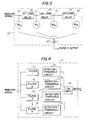
- FIG. 5 is a simplified block diagram of a generalized MTI radar processor employing the invention.
- a first canceller circuit 80a comprises a first set of doppler filters, each derived from n taps of the general transversal filter of FIG. 3, and generally represents a canceller circuit as depicted in FIG. 4, including the corresponding detection and threshold circuits and the OR gate.
- a second canceller circuit 80b generally represents a canceller circuit as depicted in FIG. 4, but with each filter derived from the first n-1 taps of the general transversal filter of FIG. 3.
- the respective outputs of each filter set canceller are then coupled as inputs to AND gate 85.
- the processor of FIG. 5 provides output signals only during the inter-pulse time interval following the nth transmitted pulse.
- FIGS. 1 and 5 have been directed to providing the capability of cancelling second range clutter.
- the technique may be extended further, e.g., employing an n-2 tap filter set with an n tap filter set to suppress second and third range interval clutter.
- the invention may be employed to process the returns from n transmitted pulses to provide a capability of providing clutter rejection capability for the first through m+1 range intervals, where n and m are both integer values, and m is less than n.
- FIGS. 1-5 are preferably implemented with digital devices to provide the functions of the various devices comprising the radar processor.
- digital devices for example, it may be advantageous in certain applications to employ shift registers as the delay devices.
- shift registers as the delay devices.
- the particular implementation details of the filter set cancellers per se are known to those skilled in the art.
Landscapes
- Engineering & Computer Science (AREA)
- Radar, Positioning & Navigation (AREA)
- Remote Sensing (AREA)
- Physics & Mathematics (AREA)
- Computer Networks & Wireless Communication (AREA)
- General Physics & Mathematics (AREA)
- Spectroscopy & Molecular Physics (AREA)
- Radar Systems Or Details Thereof (AREA)
Applications Claiming Priority (2)
| Application Number | Priority Date | Filing Date | Title |
|---|---|---|---|
| US06/882,582 US4688044A (en) | 1986-07-07 | 1986-07-07 | Multiple range interval clutter cancellation circuit |
| US882582 | 1986-07-07 |
Publications (2)
| Publication Number | Publication Date |
|---|---|
| EP0273970A1 EP0273970A1 (en) | 1988-07-13 |
| EP0273970B1 true EP0273970B1 (en) | 1992-06-17 |
Family
ID=25380910
Family Applications (1)
| Application Number | Title | Priority Date | Filing Date |
|---|---|---|---|
| EP87904787A Expired - Lifetime EP0273970B1 (en) | 1986-07-07 | 1987-07-06 | Multiple range interval clutter cancellation circuit |
Country Status (7)
| Country | Link |
|---|---|
| US (1) | US4688044A (no) |
| EP (1) | EP0273970B1 (no) |
| JP (1) | JPH01500774A (no) |
| DE (1) | DE3779894T2 (no) |
| IL (1) | IL83042A (no) |
| NO (1) | NO172821C (no) |
| WO (1) | WO1988000355A1 (no) |
Families Citing this family (16)
| Publication number | Priority date | Publication date | Assignee | Title |
|---|---|---|---|---|
| US4800387A (en) * | 1984-02-07 | 1989-01-24 | Logimetrics, Inc. | Boresight chamber assembly apparatus |
| JPS60169782A (ja) * | 1984-02-14 | 1985-09-03 | Nec Corp | 移動目標表示装置 |
| US4890113A (en) * | 1987-12-09 | 1989-12-26 | Westinghouse Electric Corp. | Second time around clutter cancellation system |
| NL8800002A (nl) * | 1988-01-04 | 1988-04-05 | Hollandse Signaalapparaten Bv | Moving target indicatie-eenheid. |
| FR2662265A1 (fr) * | 1990-05-18 | 1991-11-22 | Philips Electronique Lab | Dispositif eliminateur d'echos fixes pour echographe ultrasonore. |
| US5150426A (en) * | 1990-11-20 | 1992-09-22 | Hughes Aircraft Company | Moving target detection method using two-frame subtraction and a two quadrant multiplier |
| FR2712094B1 (fr) * | 1993-11-02 | 1995-12-01 | Thomson Csf | Procédé de détermination du rang d'ambiguïté en distance d'échos radar. |
| FR2719669B1 (fr) * | 1994-05-03 | 1996-06-07 | Thomson Csf | Procédé et dispositif d'élimination des échos fixes en fréquence intermédiaire dans un radar à impulsions cohérentes. |
| JPH08228409A (ja) * | 1995-02-22 | 1996-09-03 | Kyosan Electric Mfg Co Ltd | 現示決定処理装置 |
| US6867732B1 (en) * | 2004-08-10 | 2005-03-15 | Chung Shan Institute Of Science And Technology, Armanents Bureau, M.N.D. | Embedded multi-functional preprocessing input data buffer in radar system |
| US7095358B2 (en) * | 2004-11-23 | 2006-08-22 | Raytheon Company | Technique for cancellation of elevated clutter for the detection of fixed and ground moving targets under trees |
| WO2010103309A1 (en) | 2009-03-11 | 2010-09-16 | Bae Systems Plc | Sensor for determining velocity |
| US8471761B1 (en) * | 2010-04-23 | 2013-06-25 | Akela, Inc. | Wideband radar nulling system |
| US9864044B2 (en) * | 2014-06-25 | 2018-01-09 | Raytheon Company | Methods and systems for improving signal to phase noise in radars |
| EP3267224B1 (de) * | 2016-07-06 | 2019-02-27 | Riegl Laser Measurement Systems GmbH | Verfahren zur entfernungsmessung |
| CN108828546B (zh) * | 2018-05-24 | 2021-03-26 | 西安空间无线电技术研究所 | 一种天基多通道动目标雷达接收处理系统及方法 |
Family Cites Families (16)
| Publication number | Priority date | Publication date | Assignee | Title |
|---|---|---|---|---|
| GB892282A (en) * | 1959-03-26 | 1962-03-21 | Marconi Wireless Telegraph Co | Improvements in or relating to pulsed radar systems |
| US3109171A (en) * | 1961-02-06 | 1963-10-29 | George L Henry | Three-pulse canceller for coherent mti systems |
| US4042924A (en) * | 1970-02-25 | 1977-08-16 | Hughes Aircraft Company | MTI clutter tracking and cancelling system |
| US3828348A (en) * | 1971-10-21 | 1974-08-06 | Hughes Aircraft Co | System for minimizing multiple time around echos in a coherent-on-receive-doppler radar |
| US3879729A (en) * | 1973-07-23 | 1975-04-22 | Gen Electric | Moving target indicator with minimum clutter interference |
| US4035799A (en) * | 1975-11-04 | 1977-07-12 | The United States Of America As Represented By The Secretary Of The Navy | Digital mean clutter doppler compensation system |
| US4003052A (en) * | 1975-12-15 | 1977-01-11 | United Technologies Corporation | Digital prefilter for clutter attenuation in MTI radars |
| US4137532A (en) * | 1977-04-29 | 1979-01-30 | Westinghouse Electric Corp. | VIP doppler filter bank signal processor for pulse doppler radar |
| US4086592A (en) * | 1977-07-22 | 1978-04-25 | The United States Of America As Represented By The Secretary Of The Navy | Digital sidelobe canceller |
| US4119962A (en) * | 1977-11-23 | 1978-10-10 | The United States Of America As Represented By The Secretary Of The Navy | Multiple memory adaptive MTI |
| US4318099A (en) * | 1980-02-21 | 1982-03-02 | The United States Of America As Represented By The Secretary Of The Navy | Clutter filter using a minimum number of radar pulses |
| IT1146164B (it) * | 1980-07-16 | 1986-11-12 | Selenia Ind Elettroniche | Dispositivo di filtraggio doppler adattivo alla situazione di clutter ed ecm esterna per impianti radar |
| US4489320A (en) * | 1981-08-07 | 1984-12-18 | The United States Of America As Represented By The Secretary Of The Navy | Interference suppressor for radar MTI |
| US4450448A (en) * | 1981-08-28 | 1984-05-22 | Grumman Aerospace Corporation | Apparatus and method for improving antenna sidelobe cancellation |
| US4390881A (en) * | 1982-06-09 | 1983-06-28 | The United States Of America As Respresented By The Secretary Of The Navy | Real-data digital-real-weight canceler |
| IT1197641B (it) * | 1983-05-04 | 1988-12-06 | Selenia Ind Elettroniche | Dispositivo per l'identificazione e la soppressione di echi indesiderati di seconda traccia in sistemi radar |
-
1986
- 1986-07-07 US US06/882,582 patent/US4688044A/en not_active Expired - Lifetime
-
1987
- 1987-06-30 IL IL83042A patent/IL83042A/xx not_active IP Right Cessation
- 1987-07-06 JP JP62504317A patent/JPH01500774A/ja active Granted
- 1987-07-06 WO PCT/US1987/001653 patent/WO1988000355A1/en active IP Right Grant
- 1987-07-06 DE DE8787904787T patent/DE3779894T2/de not_active Expired - Fee Related
- 1987-07-06 EP EP87904787A patent/EP0273970B1/en not_active Expired - Lifetime
-
1988
- 1988-03-04 NO NO880981A patent/NO172821C/no unknown
Also Published As
| Publication number | Publication date |
|---|---|
| NO172821C (no) | 1993-09-08 |
| JPH0529875B2 (no) | 1993-05-06 |
| DE3779894D1 (de) | 1992-07-23 |
| DE3779894T2 (de) | 1992-12-24 |
| IL83042A (en) | 1991-06-10 |
| NO880981L (no) | 1988-03-04 |
| NO880981D0 (no) | 1988-03-04 |
| US4688044A (en) | 1987-08-18 |
| JPH01500774A (ja) | 1989-03-16 |
| EP0273970A1 (en) | 1988-07-13 |
| WO1988000355A1 (en) | 1988-01-14 |
| NO172821B (no) | 1993-06-01 |
Similar Documents
| Publication | Publication Date | Title |
|---|---|---|
| EP0273970B1 (en) | Multiple range interval clutter cancellation circuit | |
| US5376939A (en) | Dual-frequency, complementary-sequence pulse radar | |
| US4459592A (en) | Methods of and circuits for suppressing doppler radar clutter | |
| US3701149A (en) | Frequency averaging controlled false alarm rate (cfar) circuit | |
| US5151702A (en) | Complementary-sequence pulse radar with matched filtering following doppler filtering | |
| US4137532A (en) | VIP doppler filter bank signal processor for pulse doppler radar | |
| US5539412A (en) | Radar system with adaptive clutter suppression | |
| EP0133002B1 (en) | Adaptive radar signal processing apparatus | |
| US4885590A (en) | Blind speed elimination for dual displaced phase center antenna radar processor mounted on a moving platform | |
| US4249177A (en) | Target discrimination apparatus | |
| US4719466A (en) | Adaptive radar signal processor for the detection of useful echo and the cancellation of clutter | |
| US3480953A (en) | Moving target indicator having staggered pulse repetition frequency | |
| US4709236A (en) | Selectable doppler filter for radar systems | |
| US4714927A (en) | Pulse doppler radar with variable pulse repetition rate | |
| US3797016A (en) | Digital moving target indicator radar system incorporating modulo-n components | |
| US5781149A (en) | Doppler radar clutter spike rejector | |
| US4489320A (en) | Interference suppressor for radar MTI | |
| US4001826A (en) | Range-gated moving target signal processor | |
| Levanon | CW alternatives to the coherent pulse train-signals and processors | |
| Zverev | Digital MTI radar filters | |
| US3560972A (en) | Apparatus for flexibly weighting received echoes in a moving target indicator radar | |
| Remley | Doppler dispersion effects in matched filter detection and resolution | |
| GB2259209A (en) | Radar receivers | |
| US4464768A (en) | Adaptive preprocessing system | |
| JP3061738B2 (ja) | マルチprf法を用いた測距装置および測距方法 |
Legal Events
| Date | Code | Title | Description |
|---|---|---|---|
| PUAI | Public reference made under article 153(3) epc to a published international application that has entered the european phase |
Free format text: ORIGINAL CODE: 0009012 |
|
| 17P | Request for examination filed |
Effective date: 19880303 |
|
| AK | Designated contracting states |
Kind code of ref document: A1 Designated state(s): DE FR GB IT |
|
| 17Q | First examination report despatched |
Effective date: 19901009 |
|
| GRAA | (expected) grant |
Free format text: ORIGINAL CODE: 0009210 |
|
| AK | Designated contracting states |
Kind code of ref document: B1 Designated state(s): DE FR GB IT |
|
| REF | Corresponds to: |
Ref document number: 3779894 Country of ref document: DE Date of ref document: 19920723 |
|
| ET | Fr: translation filed | ||
| ITF | It: translation for a ep patent filed |
Owner name: SOCIETA' ITALIANA BREVETTI S.P.A. |
|
| PLBE | No opposition filed within time limit |
Free format text: ORIGINAL CODE: 0009261 |
|
| STAA | Information on the status of an ep patent application or granted ep patent |
Free format text: STATUS: NO OPPOSITION FILED WITHIN TIME LIMIT |
|
| 26N | No opposition filed | ||
| REG | Reference to a national code |
Ref country code: GB Ref legal event code: 732E |
|
| PGFP | Annual fee paid to national office [announced via postgrant information from national office to epo] |
Ref country code: GB Payment date: 20000620 Year of fee payment: 14 Ref country code: DE Payment date: 20000620 Year of fee payment: 14 |
|
| PG25 | Lapsed in a contracting state [announced via postgrant information from national office to epo] |
Ref country code: GB Free format text: LAPSE BECAUSE OF NON-PAYMENT OF DUE FEES Effective date: 20010706 |
|
| GBPC | Gb: european patent ceased through non-payment of renewal fee |
Effective date: 20010706 |
|
| PG25 | Lapsed in a contracting state [announced via postgrant information from national office to epo] |
Ref country code: FR Free format text: LAPSE BECAUSE OF NON-PAYMENT OF DUE FEES Effective date: 20020329 |
|
| PG25 | Lapsed in a contracting state [announced via postgrant information from national office to epo] |
Ref country code: DE Free format text: LAPSE BECAUSE OF NON-PAYMENT OF DUE FEES Effective date: 20020501 |
|
| REG | Reference to a national code |
Ref country code: FR Ref legal event code: ST |
|
| PGFP | Annual fee paid to national office [announced via postgrant information from national office to epo] |
Ref country code: FR Payment date: 20020610 Year of fee payment: 16 |
|
| PG25 | Lapsed in a contracting state [announced via postgrant information from national office to epo] |
Ref country code: IT Free format text: LAPSE BECAUSE OF NON-PAYMENT OF DUE FEES;WARNING: LAPSES OF ITALIAN PATENTS WITH EFFECTIVE DATE BEFORE 2007 MAY HAVE OCCURRED AT ANY TIME BEFORE 2007. THE CORRECT EFFECTIVE DATE MAY BE DIFFERENT FROM THE ONE RECORDED. Effective date: 20050706 |