EP0273540B1 - Method and device for controlling a short circuiting type of welding system - Google Patents
Method and device for controlling a short circuiting type of welding system Download PDFInfo
- Publication number
- EP0273540B1 EP0273540B1 EP87302155A EP87302155A EP0273540B1 EP 0273540 B1 EP0273540 B1 EP 0273540B1 EP 87302155 A EP87302155 A EP 87302155A EP 87302155 A EP87302155 A EP 87302155A EP 0273540 B1 EP0273540 B1 EP 0273540B1
- Authority
- EP
- European Patent Office
- Prior art keywords
- current
- welding
- condition
- voltage
- short
- Prior art date
- Legal status (The legal status is an assumption and is not a legal conclusion. Google has not performed a legal analysis and makes no representation as to the accuracy of the status listed.)
- Expired - Lifetime
Links
- 238000000034 method Methods 0.000 title claims description 36
- 238000005493 welding type Methods 0.000 title description 4
- 238000003466 welding Methods 0.000 claims description 157
- 239000002184 metal Substances 0.000 claims description 94
- 238000012546 transfer Methods 0.000 claims description 84
- 238000001514 detection method Methods 0.000 claims description 15
- 230000004044 response Effects 0.000 claims description 11
- 239000007787 solid Substances 0.000 claims description 11
- 239000003990 capacitor Substances 0.000 claims description 10
- 230000008859 change Effects 0.000 claims description 9
- 230000007423 decrease Effects 0.000 claims description 9
- 238000000151 deposition Methods 0.000 claims description 5
- 230000002401 inhibitory effect Effects 0.000 claims 2
- 210000003739 neck Anatomy 0.000 description 48
- 238000004880 explosion Methods 0.000 description 26
- 230000009467 reduction Effects 0.000 description 16
- 230000009471 action Effects 0.000 description 13
- 230000036470 plasma concentration Effects 0.000 description 11
- 230000001965 increasing effect Effects 0.000 description 10
- 239000011324 bead Substances 0.000 description 9
- 230000000694 effects Effects 0.000 description 7
- 239000002245 particle Substances 0.000 description 7
- 230000008569 process Effects 0.000 description 7
- 238000010586 diagram Methods 0.000 description 6
- 230000001276 controlling effect Effects 0.000 description 5
- 230000001939 inductive effect Effects 0.000 description 5
- 238000013019 agitation Methods 0.000 description 4
- 230000003247 decreasing effect Effects 0.000 description 4
- 230000006870 function Effects 0.000 description 4
- 239000007789 gas Substances 0.000 description 4
- 238000000926 separation method Methods 0.000 description 4
- 238000013459 approach Methods 0.000 description 3
- 230000008901 benefit Effects 0.000 description 3
- 230000015572 biosynthetic process Effects 0.000 description 3
- 238000004140 cleaning Methods 0.000 description 3
- 230000000875 corresponding effect Effects 0.000 description 3
- 230000008018 melting Effects 0.000 description 3
- 238000002844 melting Methods 0.000 description 3
- 238000007664 blowing Methods 0.000 description 2
- 238000011109 contamination Methods 0.000 description 2
- 230000002939 deleterious effect Effects 0.000 description 2
- 230000000994 depressogenic effect Effects 0.000 description 2
- 238000007667 floating Methods 0.000 description 2
- 239000000463 material Substances 0.000 description 2
- 230000007246 mechanism Effects 0.000 description 2
- 238000012986 modification Methods 0.000 description 2
- 230000004048 modification Effects 0.000 description 2
- 239000012768 molten material Substances 0.000 description 2
- 238000007493 shaping process Methods 0.000 description 2
- 230000001960 triggered effect Effects 0.000 description 2
- 230000003213 activating effect Effects 0.000 description 1
- 230000002411 adverse Effects 0.000 description 1
- 239000004020 conductor Substances 0.000 description 1
- 230000002596 correlated effect Effects 0.000 description 1
- 230000009849 deactivation Effects 0.000 description 1
- 230000001934 delay Effects 0.000 description 1
- 230000008021 deposition Effects 0.000 description 1
- 238000011161 development Methods 0.000 description 1
- 238000010891 electric arc Methods 0.000 description 1
- 230000001747 exhibiting effect Effects 0.000 description 1
- 230000005484 gravity Effects 0.000 description 1
- 230000001976 improved effect Effects 0.000 description 1
- 230000006872 improvement Effects 0.000 description 1
- 238000012423 maintenance Methods 0.000 description 1
- 238000005259 measurement Methods 0.000 description 1
- 239000000155 melt Substances 0.000 description 1
- 230000010355 oscillation Effects 0.000 description 1
- 230000003647 oxidation Effects 0.000 description 1
- 238000007254 oxidation reaction Methods 0.000 description 1
- 230000000630 rising effect Effects 0.000 description 1
- 238000005507 spraying Methods 0.000 description 1
- 238000003860 storage Methods 0.000 description 1
- 230000002459 sustained effect Effects 0.000 description 1
- 230000001052 transient effect Effects 0.000 description 1
- 230000007704 transition Effects 0.000 description 1
- 239000002699 waste material Substances 0.000 description 1
- XLYOFNOQVPJJNP-UHFFFAOYSA-N water Substances O XLYOFNOQVPJJNP-UHFFFAOYSA-N 0.000 description 1
Images




Classifications
-
- B—PERFORMING OPERATIONS; TRANSPORTING
- B23—MACHINE TOOLS; METAL-WORKING NOT OTHERWISE PROVIDED FOR
- B23K—SOLDERING OR UNSOLDERING; WELDING; CLADDING OR PLATING BY SOLDERING OR WELDING; CUTTING BY APPLYING HEAT LOCALLY, e.g. FLAME CUTTING; WORKING BY LASER BEAM
- B23K9/00—Arc welding or cutting
- B23K9/06—Arrangements or circuits for starting the arc, e.g. by generating ignition voltage, or for stabilising the arc
-
- B—PERFORMING OPERATIONS; TRANSPORTING
- B23—MACHINE TOOLS; METAL-WORKING NOT OTHERWISE PROVIDED FOR
- B23K—SOLDERING OR UNSOLDERING; WELDING; CLADDING OR PLATING BY SOLDERING OR WELDING; CUTTING BY APPLYING HEAT LOCALLY, e.g. FLAME CUTTING; WORKING BY LASER BEAM
- B23K9/00—Arc welding or cutting
- B23K9/09—Arrangements or circuits for arc welding with pulsed current or voltage
- B23K9/091—Arrangements or circuits for arc welding with pulsed current or voltage characterised by the circuits
-
- B—PERFORMING OPERATIONS; TRANSPORTING
- B23—MACHINE TOOLS; METAL-WORKING NOT OTHERWISE PROVIDED FOR
- B23K—SOLDERING OR UNSOLDERING; WELDING; CLADDING OR PLATING BY SOLDERING OR WELDING; CUTTING BY APPLYING HEAT LOCALLY, e.g. FLAME CUTTING; WORKING BY LASER BEAM
- B23K9/00—Arc welding or cutting
- B23K9/095—Monitoring or automatic control of welding parameters
Definitions
- the invention relates to the art of welding with an electric arc and more particularly to an improved method and device for controlling a short circuiting type welding system to drastically reduce spatter which normally accompanies this type of welding process.
- one of the recognized modes of operation is the short circuiting mode, wherein a power supply is connected across the consumable electrode, or welding wire, and the workpiece onto which a weld bead is to be deposited.
- a power supply is connected across the consumable electrode, or welding wire, and the workpiece onto which a weld bead is to be deposited.
- the end of the electrode melts to form a form a globular mass of molten metal hanging on the electrode and extending toward the workpiece.
- this mass of molten material becomes large enough, it bridges the gap between the electrode and the workpiece to cause a short circuit.
- the voltage between the electrode and the workpiece drops drastically thereby causing the power supply to drastically increase the current through the short circuit.
- This high current flow is desirable to cause the neck portion of the molten mass to form rapidly into a very small area or neck which ultimately explodes like an electric fuse to separate the molten ball from the wire and allow it to be drawn into the weld pool by surface tension.
- This explosion of the neck causes spatter from the welding process. Spatter is deleterious to the overall efficiency of the welding operation and requires a substantial amount of cleaning adjacent the weld bead after the welding operation is concluded. Since the current flow through the wire or rod to the workpiece when the neck or fuse explodes is quite high, there is a tremendous amount of energy released by the neck explosion adding to the propelled distance and amount of spatter.
- This system is not applicable for all power supplies and is predicated upon a complex logic control system which actually forms the shape of the current curve from the time a short is detected to the time when the arc is reestablished after explosion of the neck or fuse.
- Reduction of current at the time of a short is by tuned attenuation, which phenomenon causes a time constant curve between time t1 and t2.
- this same attenuation concept is employed. This feature is shown between the times t5 and t6 of this prior patent.
- the preselected wave shape is heavily reliant upon the aforementioned attenuation of the output tank circuit of a solid state inverter which is a serious limitation especially in reducing the current flow through the neck itself at the moment of explosion.
- Such a preselected current shaping is applicable, if at all, to a high frequency solid state inverter power supply which can be internally turned off without substantial output inductance. With a substantial inductive reactance in the output circuit attenuation by the resistor in parallel with switch SWD would be difficult and not always guaranteed. Since direct current welding systems have output inductance this attenuation concept for lowering spatter has serious practical drawbacks.
- the present invention overcomes the disadvantages of prior attempts to reduce spatter in a welding system of the type employing the short circuit, transfer mode which system requires a minimum of logic circuits and is applicable for a wide variety of power supplies with and without a substantial amount of inductance in the output circuit.
- the present invention provides a device as defined in claim 1, annexed hereto as well as a method for reducing spatter as defined in claim 12, annexed hereto.
- a main weld current is on whenever the arc voltage exceeds a preselected threshold level, such as 10 volts.
- a preselected threshold level such as 10 volts.
- the main welding current is turned off for a selected time and is then turned on again.
- a low background current is maintained so the molten metal mass or ball hanging from the welding wire and in contact with the workpiece either breaks away or develops into a metal transfer short under the influence of only the low background current and not the main current. Consequently, any molten metal ball which does not actually transfer to the weld bead or weld pool on the workpiece will be subject to only low background current when it separates from the weld pool.
- Such low current does not tend to propel the ball or portions thereof from the wire away from the weld pool.
- These bulbs or balls of molten metal may only momentarily engage the molten weld pool or weld bead thus causing a phenomenon referred to as an "incipient short".
- An incipient short is not a metal transfer short, but is the engagement of the ball with the weld pool succeeded by a bouncing away of the ball from the molten pool by electric pinch forces to again establish an arc without any metal transfer.
- the momentary short would occur well within the selected time of low current. In practice, this time is 1.0 ms.
- the main weld current is turned off reducing pinch forces at the contact point between the molten metal ball and the weld pool.
- the short converts into a metal transfer short and progresses without forming an incipient short.
- workpiece is used herein to indicate either the metal onto which the weld bead is being laid or deposited, the bead itself or the weld pool. All of these are electrically grounded to the power supply.
- the main current will preferably come on when the short is broken and the arc reestablished. If the incipient short condition is converted to a transfer short during the time of forced low current, which is the general result, a short condition remains after the initial preselected time of low current. The arc voltage remains at a low level, but the main current is turned on. When this occurs, the current through the molten bath between the welding wire and the workpiece increases rapidly because of the continuing short circuit between the welding wire and the workpiece. As main current continues to flow through the welding wire, the wire continues to heat and its resistivity increases.
- the ball bridging the gap starts to neck down by the electric pinch effect at a rate proportional to the square of the weld current.
- the voltage commences to increase. Since the necking action is generally self-sustaining after it starts, commencement of the neck signals an impending fuse blow preceded by an increased voltage and a change in sign of the current slope.
- a time derivative of the operating voltage or of the weld current with the main current applied across the shorted metal indicates when the metal is electrically pinched by the main current flow.
- a rapid rise in the voltage or change of slope of the weld current indicates an imminent blow of the fuse or neck.
- the main current when an imminent fuse explosion is indicated by the voltage or current derivative, the main current is again immediately turned off, just before the loss of metal contact. With the main current off, the low background current causes the fuse explosion at the neck. This is a low energy explosion without sacrificing efficient separation.
- the plasma or arc is restored by the background current and the arc voltage increases.
- the main current is again turned on awaiting the next short.
- the circuit measuring the time derivative of the voltage or current may be deactivated for a short time immediately following the first time delay after a short circuit detection. This deactivation prevents a derivative measurement or detection when the main current is turned on after the time delay. If this derivative detection feature were to function immediately after the delay, the main current would again be turned off thereby preventing the formation of a high shorting current and development of a strong electric pinch. During this transition to the main current there are variations in the voltage which could be erroneously identified as a necking condition by the circuit measuring the time derivative of the arc voltage or time derivative of the weld current.
- the invention as defined above allows the main current to switch off so that a low level background current is maintained for a preselected maximum time immediately after a short circuit detection.
- the same low level background current is preferably applied for a selected time delay. During these time delays, should the voltage increase above the selected value, thus indicating an arc condition, the main current is preferably immediately applied and the welding process continues as if there were no control over the weld current.
- the first time delay is interrupted and the main current is immediately applied whenever an arc is re-established after a short. This occurs during an incipient short.
- the main current then increases to the plasma level awaiting an actual transfer short. Consequently, the metal ball at the end or the welding wire is not subjected to high propelling forces.
- the molten balls do not tend to grow by repeated momentary shorts separated by arc jets.
- the present invention recognizes and overcomes the problems caused by incipient shorts by allowing actual metal transfer to the weld pool during normal transfer shorts, but also providing only a low current condition during the formation of incipient shorts.
- the present invention may override the low or background current control feature whenever there is an arc, immediately following a short circuit condition, such as would occur with an incipient short, if one should appear.
- incipient shorts are generally avoided.
- the weld current is not forced through a preselected combination of current levels based purely on time cycles, as sometimes employed in the prior art for reason other than control of incipient shorting.
- incipient shorting as a mechanical component of spatter and utilizing the present invention to eliminate nearly all incipient shorts is a substantial improvement in spatter control.
- every short is assumed to be an incipient short and the welding current is reduced to a background level so the agitation of the weld pool and the forces of the arc are minimized. This greatly increases the probability that even an incipient contact between the molten ball and the molten weld pool will be converted into a normal, desirable transfer short by attraction of the weld pool surface.
- spatter can be reduced drastically over normal short circuiting type welding without the complexity and current wave shaping of other spatter reduction techniques.
- Use of the present invention reduces the violent oscillations of the molten weld pool which further reduces tendency of spatter. Further, a more quiescent weld pool allows the surface tension to better bridge the root gap between two pieces being welded. Also, the pool will better conform to the pieces being welded with the reduced agitation caused by high energy fuse explosions and incipient shorts.
- the weld pool when less agitated, allows use of larger electrodes in out of position welding. Short arc lengths can be maintained without stubbing. Consequently, the invention allows use of large electrodes, high deposition rates, high currents and, also, less contamination by entrapment of shielding gases.
- the primary object of the present invention is the provision of a method and device for controlling current between a main welding current and a background welding current in a manner to drastically reduce spatter in a short circuiting type of welding system.
- present invention may be used to provide the following:
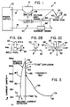
- FIGURE 1 illustrates a welding system A constructed in accordance with the present invention.
- System A contains a spatter reduction or control circuit SC which will be desired later. Since spatter control circuit SC is capable of addition to a standard short circuit type welding unit, system A of FIGURE 1 illustrates components common to a welding operation whether or not inventive circuit SC is used.
- FIGURE 1 will initially be employed to explain general background and concepts used in short circuit type welding.
- the commonly used components of system A include a conventional transformer type power supply 10 having a constant voltage output with inductive reactance internal to the power supply that prevents rapid discontinuation of welding current using normal solid state switching procedures.
- Output leads 12, 14 are connected in series across gas nozzle 20, welding wire 22 and workpiece 30. These components are arranged in a series circuit schematically illustrated in FIGURE 1; however, a mechanism for feeding the wire 22 toward the weld pool on workpiece 10 for the purpose of laying a bead along the workpiece would be an integral component of system A. Such normal wire feeding mechanism does not form a part of the present invention.
- the present invention can be used in a standard short circuiting mode of welding as so far explained with the aid of standard components illustrated in system A of FIGURE 1.
- This system employs a conventional transformer type power supply applying an arc voltage across wire 22 and arc or plasma P. Such voltage causes a weld current to flow from wire 22 to workpiece 30.
- an appropriate shielding gas 40 is directed from nozzle 20 around wire 22 to reduce oxidation and contamination of the metal being deposited in the weld pool on the workpiece 30.
- either workpiece 30 or welding head including nozzle 20 is moved along a desired path to deposit a linear welding bead either on the surface of the workpiece or in a groove formed between two abutting workpieces.
- the metal is deposited from the wire onto the workpiece by passage of a welding current through the wire and to the workpiece which alternates between a short circuit condition wherein the rod or wire touches the workpiece and an arc condition or plasma condition, wherein there is a gap between the wire and workpiece.
- This gap below the wire is spanned by an arc or plasma.
- workpiece refers to the weld pool already deposited on the surface being treated or the workpiece itself, which definition is used herein for convenience.
- FIGURES 2A, 2B and 2C schematically illustrate the short circuiting transfer phenomenon for transferring metal melted at the end of wire 22 and deposited on the workpiece by the surface tension drawing the metal into the weld pool of molten metal containing the previously deposited metal.
- This weld pool is dynamic in nature and retains its fluidity for a substantial time after nozzle 20 progressively moves along the workpiece.
- the bottom of wire 22 is maintained spaced from the workpiece or molten weld pool previously deposited a distance b which is substantially greater than the diameter a of the wire.
- diameter a can vary substantially and still be used in a welding system using the present invention.
- molten metal bulb or ball B shown in FIGURE 2A, has a geometric spherical shape somewhat greater than a hemisphere. This ball shape facilitates separation and surface tension transfer from rod 22 to the molten weld pool or work piece 30.
- Welding current I W has a normal arc or plasma current level I P which is a minimum current level and is controlled primarily by the output resistance. Between arc or plasma periods when plasma current I P is flowing, there is a metal transfer short pulse MT where welding current I W is increased and then decreased back to plasma current I P .
- Pulse MT which is standard when a transfer short occurs, includes a leading, rapidly rising curved side 50, which increases to a maximum from the point S.
- a short condition is illustrated in FIGURE 2A.
- ball B clings by surface tension to the molten weld pool and forms a distinct neck N in accordance with the electric pinch effect. The diameter of the neck N is reduced by current induced forces in accordance with the Northrup equation.
- ball B forms on the end of wire 22 and enlarges until it makes contact with the weld pool or workpiece 30 shown in FIGURE 2A.
- Surface tension then draws ball B from the end of rod 22 preparatory to the electric pinch effect causing ball B to neck down as shown at N in FIGURE 2B.
- the fuse breaks or blows, as shown in FIGURE 2C.
- FIGURE 3 As shown in FIGURE 3, at the fuse F, the current is nearly 300 amperes; therefore, tremendous energy is released when ball B separates from wire 22.
- wire 22 was reduced in size so as to bury the arc in the weld pool, thus, permitting the weld pool to catch most of the spatter particles of molten metal and reduce the tendency to drive the spatter particles away from the weld pool.
- complex circuits were suggested to control the shape of metal transfer pulse MT during the metal transfer cycle. These prior arrangements tended to drive pulse MT in a preselected pulse shape. Often the pulses were repeated, irrespective of whether they were needed or not or whether the metal transfer actually occurred.
- the present invention overcomes these disadvantages by making only minor modifications in the conventional system so far discussed with respect to certain components of system A in FIGURE 1.
- the normal welding current curve, as shown in FIGURE 3 is controlled by simple, easily accomplished structural modifications of the normal short circuit system so far described.
- spatter reduction circuit SC includes resistor R connected in parallel with a Darlington power transistor switch SW. This parallel circuit is connected in series with nozzle 20, wire 22 and workpiece 30.
- spatter reduction circuit SC also includes solid state logic control system L for operating switch SW. The manner of operating the switch in relationship to parameters at the welding site substantially eliminates spatter SP experienced in standard short circuit welding. Control L commands Darlington switch SW to be either conductive or non-conductive.
- resistor R When non-conductive, resistor R is in series with the welding operation to create a low level welding current hereinafter referred to as the background current I B .
- resistor R In practice, resistor R is 1.0 Ohms which developes approximatey 300 volts across the resistor when switch SW is turned off while the main current flow is near 300 amperes. Consequently, power supply 10 is never actually disconnected or grounded to reduce the current flow through the welding operation irrespective of the status of switch SW.
- Merely switching between a direct connection through switch SW and current flow through only resistor R causes welding current I W to either (a) float, in accordance with standard pulse MT or (b) be driven downward by opening switch SW with a logic control L.
- One aspect of the present invention is the use of a Darlington connected power transistor having a rating of several hundred amperes and several hundred volts.
- the Darlington connected transistor network SN is preferred because of capabilities of rapid switching under heavy current conditions.
- This type switch is part of the present invention which must drop the welding current from a high level main current to a low level background current I B within less than about 120 microseconds when the switch is opened or in the non-conductive condition.
- An appropriate voltage sensor schematically represented as device 60, and a current sensor 62 provide logic control L with instantaneous welding current I W and arc voltage E ARC so that logic control L opens and closes switch SW to provide the weld current control as illustrated in FIGURE 4.
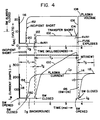
- the basic aspects of the present invention are set forth in graphic form in the upper graph of FIGURE 4, which graph illustrates voltage fluctuations.
- the lower graph illustrates welding current I W through the wire and workpiece as correlated on a time base with the upper voltage curve.
- FIGURE 4 To appreciate one aspect of the present invention to reduce the fuse energy to reduce spatter SP,attention is directed to the right hand end of the metal transfer pulse MT (NEW) in FIGURE 4.
- This pulse has a front curved shape, side or line 100 correlating directly with portion 102 of the arc voltage which will be described in connection with another aspect of the invention used at the left end of pulse MT.
- the slope decreases eventually, which change in current at the right end of line 100 causes a slight increase in the voltage slope at portion 104.
- This increase in voltage corresponds with the upper, generally flat portion of transfer pulse MT (NEW).
- the neck N is starting to form, as shown in FIGURE 2B.
- switch SW is opened. This immediately shifts the current to the low background current level I B schematically illustrated as about 50 amperes in FIGURE 4. The welding current stays at this low background level only so long as the arc voltage E ARC does not exceed a preselected value, such as 10 volts illustrated in the upper voltage curve. Then the neck breaks, the short circuit is removed and the voltage rises along vertical line 106. When arc voltage E ARC exceeds the selected low level (i.e.
- Pulse MT causes metal transfer from the welding rod to the workpiece, i.e. the molten weld pool, as did the conventional metal pulse MT.
- the time T P in FIGURE 4 is the metal transfer portion of the pulse.
- the first aspect of the present invention occurs at the end of pulse MT (NEW) and involves recognizing when the neck starts to anticipate a fuse blow. Then welding current I W is shifted to a low level substantially below the plasma level I P by opening switch SW and again allowing flow of only background current I B by interposing resistor R, as shown in FIGURE 1. A low current, low energy fuse explosion occurs. At the explosion, the metal transfer pulse is concluded, an arc is established and the voltage rises along line 106. This closes switch SW.
- the main current is permitted to flow and it increases along time constant portion 110 which starts from the low level I B , illustrated to be less than 50 amperes in FIGURE 4.
- the rapid increase in welding current along line 110 toward the plasma level 112 is a time constant curve.
- switch SW current restoration does not swing upwardly above the normal plasma level I P .
- Such unwanted current swing would cause control difficulties in restriking the arc since the applied current would be substantially higher than needed for actual plasma ignition and maintenance.
- the circuit SC is designated to drop the current to a low level upon recognizing an imminent fuse explosion. Further, the welding current I W is held to the low background level I B for a time T3 which, in practice, is 1.0 ms.
- circuit SC has a control parameter so that whenever voltage V ARC exceeds a preselected level, 10 volts in this instance, switch SW is closed. Since the arc voltage rises when neck N breaks, the rise in voltage always occurs prior to the time T3. Consequently, the holding action of circuit SC for the time delay T3 is only a fail-safe feature assuring that current I W , will ultimately be released for movement to plasma level I P at point or position 112 after being shifted to the background level I B along generally vertical line 114 just before the neck blows.
- one circuit for detecting top 52 of a metal transfer pulse is illustrated as a di/dt detector, whereby as the current shifts from a positive slope to a zero slope, an appropriate output from line 120 is processed by logic control L and is used to open switch SW.
- This circuit takes the first derivative of the welding current I W by differentiator 122.
- the derivative in line 124 is amplified by amplifier 126 and directed to input 128 of comparator 130.
- the output provides a logic signal indicating when K di/dt is at a preselected level.
- Other arrangements could be provided for detecting the top 52 of pulse MT.
- the time between this top 52 and fuse break point 54 is indicated by the spacing T N .
- spatter control SC is provided with a feature that reduces spatter caused by the phenomenon of incipient shorts.
- the arc or plasma current I P is immediately dropped to less than 50 amperes (i.e. the background level I B ) when any type of short occurs.
- the voltage drops rapidly along line 116, current I W drops along line 118 by logic control L opening switch SW.
- the welding current I W is shifted to the background current I B when the short first occurs.
- Background current I B is controlled primarily by the value of resistor R and is held for a preselected time or cycle T1 at I B .
- switch SW is closed and the voltage at low level 120 commences to rise to steady state level 102, as previously discussed. This drop of current as soon as a short is detected and holding the low level for a selected time eliminates incipient spatter.
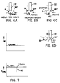
- FIGURE 6A when ball B is formed on the end of wire 22, the ball, in some instances, does not immediately attach to the molten weld pool by surface tension. The ball may just touch the weld pool as illustrated in FIGURE 2B. This is explained by recognizing that the weld pool is molten metal subjected to high arc currents as well as gravity and magnetomotive forces. It resembles a wavy body of water.
- the weld pool engages the ball B, as shown in FIGURE 6B, for a short time by a molten metal front striking ball B.
- the electrical and mechanical forces caused by wave fronts in the weld pool engaging ball B sometimes drives the ball away from the undulating weld pool. This is shown in FIGURE 6C. Consequently, there is a short when ball B touches the weld pool WP. This short can be immediately opened by mechanical forces, as shown in FIGURE 6C.
- ball B can be driven away from the weld pool as a substantial mass of molten metal. This is a form of spatter.
- FIGURE 7 illustrates the current and voltage fluctuation during an incipient short when ball B touches weld pool WP as shown in FIGURE 6B. As the ball touches but does not transfer, it swings away as illustrated in FIGURE 6C. The current through ball B increases as the ball touches the weld pool. This increased current causes forces as the arc is reestablished, in FIGURE 6C, tending to drive ball B away from the weld pool.
- An incipient short causes the arc voltage to shift downwardly as the current increases between the weld pool and the touching ball. This is shown in the lower curve of FIGURE 7. As soon as there is a break caused by mechanical forces between the ball and the weld pool, the voltage moves vertically upwardly along line 130 to the plasma arc voltage level. Since there is no large area contact for surface tension to draw molten ball B into the weld pool in an incipient short condition, the incipient short causes ball B to grow and causes high mechanical forces to exert momentum to the ball B tending to throw the ball away from the weld pool.
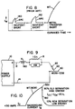
- the incipient short phenomemon is schematically illustrated in FIGURE 8 wherein the weld current I W experiences a series of incipient shorts before an active transfer short.
- the molten ball remains molten after one or more incipient shorts and then goes into a standard transfer without causing large particle spatter. However, often this does not occur.
- the incipient shorts cause ball B to grow and be propelled outwardly by the high mechanical forces during the short circuit condition. If the effect of incipient shorts, illustrated as small pulses 140, 142, in FIGURE 8, is ignored, large particle spatter will occur. This type of weld spatter presents more cleaning problems than spatter caused by breakage of fuse F in FIGURE 2C.
- the "incipient short" graph portion of FIGURE 4 illustrates what happens should an incipient short occur as the result of some transient mechanical agitation, during time T1 when the low level current I B is applied.
- the cycle or time T1 is 1.0 ms, which time is substantially greater than incipient short duration determined by the width of pulses 140, 142 of the prior art as shown in FIGURE 8.
- the overriding control recognizes the reduction of the arc voltage to a value below the preselected trip value.
- the weld current is shifted downwardly by opening switch SW.
- the current flowing during any short is reduced thus reducing mechanical forces known to cause an incipient short condition.
- the current I B is drastically below the main current level, thus facilitating large area contact and transfer of the ball to the weld pool.
- Power supply 10 is a constant voltage machine set at a plasma voltage of approximately 20-30 voltage and it feeds a short in the general range of 1-6 volts.
- applying a main current by closing switch SW allows the welding current to reach the normal unimpeded current level schematically illustrated as the increasing line 100 in FIGURE 4.
- resistor R controls the welding current at the low, background level I B .
- the main current is the normal unimpeded current and the background current is the current controlled by the resistor.
- the current when switch SW is closed rises, as shown by pulse MT (NEW), from a low level background current I B to a detected top portion 52a, at which time switch SW is opened and the current plunges along portion 180.
- pulse MT N-wave
- This action is affected by the time constant including inductive reactance X L of choke 190 which is usually inside power supply 10.
- This inductance is also created by the length of conductors 12, 14 extending from the power supply to nozzle 20 and workpiece 30.
- the time to plunge from top 52a to the background current I B represented in the disclosed formula as I O , is relatively short.
- the current at the time of the fuse break will depend upon the lead time of switch turn off before the fuse break. Lead times have been selected to cause the fuse break at approximately 10% of the height at the top 52a when it is 200 amperes.
- This current reduction after reaching top 52a combined with the initial drop from plasma current I P to background current I B , results in a substantial reduction in the separation energy when fuse F explodes or blows in response to further current flow through welding wire 22. Reduction of energy is thus accomplished by two phenomena.
- One is starting the transfer pulse at a low background level, i.e. in practice less than 50 amperes.
- the second is using a Darlington transistor switch to immediately open the switch and drive current to a level controlled by resistor R.
- a power supply or welding system employing the present invention has three distinct stages determining the welding current. At first, the current is the plasma level during the arcing condition. Secondly, the current is depressed to a background level in response to a short circuit. Thirdly, at the end of a short circuit formed by metal transfer, the current is again depressed. During the transfer of metal, the current is controlled by the electrical parameters of the circuit.
- FIGURE 11 This view corresponds generally to the pulse MT (NEW) in the lower portion of FIGURE 4.
- switch SW is closed to direct main current through the switch to the welding operation. The main switch is closed during the pulse MT (NEW); however, background voltage V B in portion 120 of FIGURE 4 shifts upwardly to the generally horizontal portion 102.
- FIGURE 11 illustrates a time delay T2 which is, in practice, 100 microseconds and occurs immediately after cycle T1.
- this delay cycle When this delay cycle is employed in the preferred embodiment of the present invention, it inhibits the circuit used to detect when the fuse is about to blow which is at a position near top 52a of curve 100.
- Such a circuit is illustrated in FIGURE 5 to detect the change in sign of di/dt.
- FIGURE 13 discloses a circuit which measures and detects a preselected slope or derivative of the arc voltage, i.e. dv/dt. These detector circuits are inhibited until time delay T2 expires. The reason for this feature is appreciated when considering portion 122 of the arc voltage immediately upon closing switch SW as shown in FIGURE 4.
- Time delay T3 follows the detection signal 200 caused by a detection of the point on curve 100 just before fuse explosion or blow and has a maximum value. Time delay T3 is shown in FIGURE 11; however, it is seldom, if ever used.
- switch SW is opened in response to a detect signal 200, the fuse blows with low current flow. An arc condition then forces the voltage along line 106 of FIGURE 4 to above the 10 volt limit, an action that closes switch SW and causes the current to rise along line 110 to portion 112, which is the plasma current level.
- Control of the background current occurs when a control signal 210 opens switch SW as illustrated schematically in FIGURE 12. That event places resistor R (1.0 Ohms) directly into the welding circuit and removes current flow through switch SW.
- resistor R 1.0 Ohms
- the plasma current I P is approximately 300 amperes.
- the switch is opened in response to the plunge in the arc voltage by a short condition, the 300 ampere current flowing when the switch is closed, develops 300 volts across resistor R. This high voltage is applied directly across Darlington transistor switch SW.
- capacitor 192 having a value of 30 mf, is connected in parallel with the resistor R.
- resistor R immediately charges capacitor 192 toward the 300 volts of the resistor. In this example, it would require about 30 microseconds for capacitor 192 to charge to 300 volts. The actual fall time of the Darlington collector current is less than 5 microseconds; therefore, charging of capacitor 192 protects Darlington transistor against excessive power switching dissapation.
- a snubber or diode 194 prevents discharge of capacitor 192 through the switch SW, should the switch close when capacitor 192 is fully charged.
- Resistor R has at least two distinct functions in accordance with the present invention. The resistor establishes the magnitude of the background current I B . If the voltage from power supply 10 is 20 volts D.C.
- background current is 20 amperes calculated by dividing 20 volts by 1.0 Ohm.
- resistor R protects the Darlington transistor switch SW against over voltage.
- a basic advantage of resistor R is that with resistor R in parallel with the Darlington switch SW there is no need for a second source of current to produce the background current. Further, there is no need for complicated circuitry attempting to control current based on sensed conditions or parameters. Merely placing resistor R in parallel with Darlington switch SW produces the main current, when the switch is closed, and the background current I B when the switch is opened.
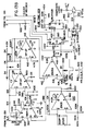
- FIGURES 13A and 13B taken together, describe the preferred circuit for practicing the invention, as best shown in FIGURES 4 and 11.
- Each of the components is labeled; therefore, the circuitry is somewhat self-explanatory and only a brief description of the operation of the circuit is sufficient to understand how the circuit complies with the parameters of the present invention.
- the arc voltage passes through a noise reduction circuit 300 having an output 302 labeled ARC VOLTAGE.
- a reference voltage in line 304 is combined with output 302 by comparator 310 to produce a logic level in output 312.
- the logic in this line controls a mono-stable multivibrator or ball pulse generator 320 which is triggered when the logic in line 312 shifts to zero indicating that the ARC VOLTAGE has decreased below the reference set in line 304.
- a 1.0 ms negative pulse appears in the Q output 322 for controlling NAND gate 330.
- a logic 0 in line 322 forces the output 332 of NAND gate 330 to be at a logic 1.
- the control of line 322 corresponds generally with control signal line 210 of FIGURE 12. In this manner, the switch SW is turned off for 1.0 ms corresponding to cycle T1.
- reset generator 350 having an input 352 connected with line 312 shifts output line 354 to a logic 0, thus, clearing ball pulse generator 320 and terminating the T1 time pulse.
- a logic 1 is applied to the input line 322 of gate 330.
- the reset logic in line 354 resets fuse time generator 360, if it is not already reset or cleared.
- a logic 1 is thus applied, as a pulse, to line 362.
- This logic combines with logic 1 on input 322 to produce a logic 0 in line 332.
- This turns the Darlington transistor switch SW on whenever arc voltage exceeds the preselected value set, in the preferred embodiment, at 10 volts. This voltage is selected to be greater than the voltage drop across wire 22 to assure enough available voltage drop for proper detection.
- FIGURE 13 including both FIGURES 13A and 13B, a derivative of the arc voltage is compared to a constant K for the purpose of predicting the fuse immediately upon establishment of neck N. This is illustrated schematically in the upper portion of FIGURE 4 at portion 104.
- the preferred circuit in FIGURE 13 uses a sample and hold concept.
- a sample oscillator 380 produces a series of sample pulses in output 382. This is applied to the sample and hold circuit 390 to sample the voltage at precisely spaced instances as the voltage is received on line 302.
- sample and hold circuit 390 The output of sample and hold circuit 390 is line 392 which compares a held sample voltage with an instantaneous voltage in line 302. These two time spaced voltages (i.e. V N and V N -1) are compared by comparator 400 to produce a differential in voltage as compared to time. This differential signal is amplified by amplifier 410 to create a differential of voltage with respect to time in line 412. The constant or K is selected by pot 414 which directs a selected constant through line 416 at the input of flip-flow 420 through line 418. When the dv/dt exceeds slope K, flip-flop 420 is clocked. This applies a logic 1 in line 422 producing a logic 0 in line 362 turning off circuit 340 by a logic 1 in line 332.
- switch SW when the voltage is less than 10 volts, switch SW is open for a time T1 which may be overridden by a voltage increasing above 10 volts, such as would occur in an incipient short. This will cause interruption of cycle T1, as indicated by line 152 in FIGURE 4.
- flip-flop 420 With the switch SW closed during a short circuit, flip-flop 420 is awaiting a signal in line 418 indicating that dv/dt has exceeded constant K. When that occurs, a 1.0 ms pulse occurs in line 362 holding line 332 at a logic 1. This is the time or cycle T3, shown in FIGURE 4, which cycle is generally never reached and is only a feature providing back-up assurance that the system will shift to the plasma current after a short.
- the inhibit feature indicated by time T2 as shown in FIGURE 4 assures that the derivative flip-flop 420 does not operate until 100 microseconds after T1 is concluded.
- This is accomplished by another monostable multivibrator 430 having an output 432 which is combined logically with the logic in ball pulse line 322 by NAND gate 440.
- the output 442 is labeled HOLD CLEAR. It remains at a logic 1 until cycle T1 expires as indicated by the logic in line 322. Thereafter the 100 microsecond negative pulse on line 432 expires.
- This pulse is shown at the bottom of FIGURE 13B.
- flip-flop 420 can not toggle to place a logic 1 in line 422. Consequently, time T2 at the end of cycle T1 maintains the differential circuit inactive for a short time allowing the voltage and current to stabilize and operate in a floating condition awaiting an ultimate detection at or near the top 52a of metal transfer pulse MT (NEW).
- the top graph depicts stages of a standard short circuiting welding operation with arc jet forces and plasma created at the first stage I.
- the ball starts to grow in stages II and III.
- an incipient short occurs with spatter at stage IV.
- the ball starts to neck at stage V.
- the fuse blows at stage VI.
- Current and voltage curves for these stages are illustrated for a system without a spatter reduction device of the present invention and labeled "Standard Process".
- the corresponding process curves using the present invention are set forth at the lower portion of FIGURE 14.
- the present invention maintains a controlled plasma current as well as controlling the transfer pulse to nearly eliminate weld spatter.
- a voltage responsive override whereby the main current is applied by closing switch SW whenever the voltage exceeded a preselected value, in the illustrated embodiment 10 volts.
- This override voltage is generally selected as about half of the arc or plasma voltage.
- the invention relates to a device for reducing spatter when a welding power supply is employed for depositing metal from a welding wire on to a workpiece by a short circuiting transfer mode wherein a welding current causes the welding wire to alternate between a short circuit condition and an arc condition, with metal transfer during a short circuit condition requiring a transfer time T p during which transfer time the welding current rises and then falls.
- the device may comprise:
- the device may otherwise comprise:
- the device may alternatively comprise:
- the device may comprise:
- the device may include means for sensing the arc voltage and wherein said first shifting means is responsive to said arc voltage being less than a selected value and second shifting means is responsive to said arc voltage being greater than a selected value, the two selected voltage values being preferably substantially equal.
- the invention also relates to a method of reducing spatter when a welding power supply is employed for depositing metal from a welding wire on to a workpiece by a short circuiting transfer mode wherein a welding current causes the welding wire to alternate between a short circuit condition and an arc condition, with metal transfer during a short circuit condition requiring a transfer time T p during which transfer time the welding current rises and then falls.
- the method may comprise the steps of:
- the parameter is the slope of the voltage curve during a selected portion of said transfer time.
- the method may otherwise comprise the following steps:
- the method may include sensing the arc voltage, actuating said first shifting step in response to said arc voltage being less than a selected value and activating said second shifting step in response to said arc voltage being greater than a selected value.
- the sensing step may include the further steps of:
- the dv/dt of the arc voltage may be detected, followed by detecting when the slope of dv/dt equals a selected value.
Landscapes
- Engineering & Computer Science (AREA)
- Physics & Mathematics (AREA)
- Plasma & Fusion (AREA)
- Mechanical Engineering (AREA)
- Arc Welding Control (AREA)
Description
- The invention relates to the art of welding with an electric arc and more particularly to an improved method and device for controlling a short circuiting type welding system to drastically reduce spatter which normally accompanies this type of welding process.
- In consumable electrode arc welding, one of the recognized modes of operation is the short circuiting mode, wherein a power supply is connected across the consumable electrode, or welding wire, and the workpiece onto which a weld bead is to be deposited. As an arc is created, the end of the electrode melts to form a form a globular mass of molten metal hanging on the electrode and extending toward the workpiece. When this mass of molten material becomes large enough, it bridges the gap between the electrode and the workpiece to cause a short circuit. At that time, the voltage between the electrode and the workpiece drops drastically thereby causing the power supply to drastically increase the current through the short circuit. Such high current flow is sustained and is actually increased with time through the molten mass as the power supply inductance is overcome. Since this short circuit current continues to flow, an electric pinch necks down a portion of the molten mass adjacent the end of the welding wire. The force causing the molten welding wire to neck down is proportional to the square of the current flowing through the molten metal at the end of the welding wire. This electric pinch effect is explained by the Northrup equation:

I is current density, r is the distance from the center of the welding wire and R is the diameter of the neck. During the short circuit, there is a need for a relatively high current flow, which flow naturally results when the short circuit occurs. This high current flow is desirable to cause the neck portion of the molten mass to form rapidly into a very small area or neck which ultimately explodes like an electric fuse to separate the molten ball from the wire and allow it to be drawn into the weld pool by surface tension. This explosion of the neck causes spatter from the welding process. Spatter is deleterious to the overall efficiency of the welding operation and requires a substantial amount of cleaning adjacent the weld bead after the welding operation is concluded. Since the current flow through the wire or rod to the workpiece when the neck or fuse explodes is quite high, there is a tremendous amount of energy released by the neck explosion adding to the propelled distance and amount of spatter. - As can be seen, there is contradiction between the short circuit current which should be high to efficiently decrease the neck size by an electric pinch, but should be low to reduce the energy of the fuse explosion and, correspondingly, reduce the spatter and distance over which the spatter particles will be propelled.
- A considerable amount of effort has been devoted to limiting spatter when the arc is reestablished by the explosion at the neck or fuse of the metal ball hanging from the welding wire and engaging the workpiece or weld pool. At first, it was suggested to reduce the diameter of the welding wire, i.e. use a 1/32 wire; however, this approach to reducing spatter caused all of the inefficiencies normally associated with using small welding wire. For instance, it was difficult to lay large amounts of weld bead and the wire sometimes stubbed or entered the weld pool without melting. As the wire diameter increased to overcome these problems, spatter was substantially increased. Faced with this dilemma, it was suggested that a high frequency power supply be used as taught in United States Patent 4,544,826, incorporated by reference herein, wherein a high frequency inverter is turned off during a short circuiting condition or upon detection of a premonition of rearcing, i.e. blowing of the fuse. To prevent circulating currents when a high frequency power supply is turned off just before a fuse explosion, this United States Letters Patent illustrates a switch, SWD, which is opened to place a resistor in the output tank circuit of the solid state inverter for rapid attenuation of the circulating currents. This system is not applicable for all power supplies and is predicated upon a complex logic control system which actually forms the shape of the current curve from the time a short is detected to the time when the arc is reestablished after explosion of the neck or fuse. Reduction of current at the time of a short is by tuned attenuation, which phenomenon causes a time constant curve between time t₁ and t₂. At the detection of a neck or fuse which is about to blow, this same attenuation concept is employed. This feature is shown between the times t₅ and t₆ of this prior patent. The preselected wave shape, as shown in this patent, is heavily reliant upon the aforementioned attenuation of the output tank circuit of a solid state inverter which is a serious limitation especially in reducing the current flow through the neck itself at the moment of explosion. Such a preselected current shaping is applicable, if at all, to a high frequency solid state inverter power supply which can be internally turned off without substantial output inductance. With a substantial inductive reactance in the output circuit attenuation by the resistor in parallel with switch SWD would be difficult and not always guaranteed. Since direct current welding systems have output inductance this attenuation concept for lowering spatter has serious practical drawbacks.
- Another patent showing a system for creating a repetition of a current cycle originally triggered by a short circuit detection is United States Letters Patent No. 4,546,234. Again, the current wave form is somewhat fixed. After a preselected time delay, current is applied across the shorted molten metal globular or ball to facilitate metal transfer. A constant current is maintained until necking is predicted, at which time the current drops rapidly to a low level and then immediately shifts up to a second high level. This system causes preselected current wave forms which are complex and generally usable, if at all, only with a high frequency solid state inverter type power supply.
- As can be seen, there is a definite need for a relatively simplified system for reducing weld spatter by exerting a limited amount of actual control over weld current flow so that the current flow can assume natural operating characteristics over most of the cycle between the short and the fuse explosion. In addition, there is a substantial demand for a spatter reducing circuitry to be used with both transformer fed and solid state inverter type power supplies which do not depend upon output attenuation of low inductance circuits nor upon several distinct current level limitations.
- Methods of arc welding aimed at reducing spatter are disclosed in Patent Abstracts of Japan, vol. 10, no. 83, (M-466) (2140) 2nd April 1986; JP-A-60 223 661 and JP-A-60 223 662. By the methods discussed in these publications, the welding voltage is compared with a reference level to detect a short circuit condition which results in a sudden drop of the voltage. A preselected pulse current is applied instead of the usual power supply current during a short circuit condition to control the metal transfer.
- The present invention overcomes the disadvantages of prior attempts to reduce spatter in a welding system of the type employing the short circuit, transfer mode which system requires a minimum of logic circuits and is applicable for a wide variety of power supplies with and without a substantial amount of inductance in the output circuit.
- The present invention provides a device as defined in
claim 1, annexed hereto as well as a method for reducing spatter as defined inclaim 12, annexed hereto. - Thus, according to the invention, a main weld current is on whenever the arc voltage exceeds a preselected threshold level, such as 10 volts. When the arc voltage drops below this preselected value, the main welding current is turned off for a selected time and is then turned on again. During this period or cycle a low background current is maintained so the molten metal mass or ball hanging from the welding wire and in contact with the workpiece either breaks away or develops into a metal transfer short under the influence of only the low background current and not the main current. Consequently, any molten metal ball which does not actually transfer to the weld bead or weld pool on the workpiece will be subject to only low background current when it separates from the weld pool. Such low current does not tend to propel the ball or portions thereof from the wire away from the weld pool. These bulbs or balls of molten metal may only momentarily engage the molten weld pool or weld bead thus causing a phenomenon referred to as an "incipient short". An incipient short is not a metal transfer short, but is the engagement of the ball with the weld pool succeeded by a bouncing away of the ball from the molten pool by electric pinch forces to again establish an arc without any metal transfer. The momentary short would occur well within the selected time of low current. In practice, this time is 1.0 ms. As incipient shorts are created, the main weld current is turned off reducing pinch forces at the contact point between the molten metal ball and the weld pool. By maintaining the welding action with a low level current flow there is sufficient current to maintain the melting action but generally insufficient current to create high level pinch forces tending to re-establish the arc and allow arc jet forces to propel the molten ball from the weld pool. Consequently, the short converts into a metal transfer short and progresses without forming an incipient short. The term "workpiece" is used herein to indicate either the metal onto which the weld bead is being laid or deposited, the bead itself or the weld pool. All of these are electrically grounded to the power supply.
- If the short circuit is only a momentary short associated with an incipient short condition, the main current will preferably come on when the short is broken and the arc reestablished. If the incipient short condition is converted to a transfer short during the time of forced low current, which is the general result, a short condition remains after the initial preselected time of low current. The arc voltage remains at a low level, but the main current is turned on. When this occurs, the current through the molten bath between the welding wire and the workpiece increases rapidly because of the continuing short circuit between the welding wire and the workpiece. As main current continues to flow through the welding wire, the wire continues to heat and its resistivity increases. The ball bridging the gap starts to neck down by the electric pinch effect at a rate proportional to the square of the weld current. As the resistivity increases and as the neck decreases in diameter, the voltage commences to increase. Since the necking action is generally self-sustaining after it starts, commencement of the neck signals an impending fuse blow preceded by an increased voltage and a change in sign of the current slope. A time derivative of the operating voltage or of the weld current with the main current applied across the shorted metal indicates when the metal is electrically pinched by the main current flow. A rapid rise in the voltage or change of slope of the weld current indicates an imminent blow of the fuse or neck. According to the preferred embodiment of the present invention, when an imminent fuse explosion is indicated by the voltage or current derivative, the main current is again immediately turned off, just before the loss of metal contact. With the main current off, the low background current causes the fuse explosion at the neck. This is a low energy explosion without sacrificing efficient separation. During separation of the bridging metal, the plasma or arc is restored by the background current and the arc voltage increases. When the arc voltage exceeds the control value, the main current is again turned on awaiting the next short.
- To prevent interruption of the main current immediately after a short is detected, the circuit measuring the time derivative of the voltage or current may be deactivated for a short time immediately following the first time delay after a short circuit detection. This deactivation prevents a derivative measurement or detection when the main current is turned on after the time delay. If this derivative detection feature were to function immediately after the delay, the main current would again be turned off thereby preventing the formation of a high shorting current and development of a strong electric pinch. During this transition to the main current there are variations in the voltage which could be erroneously identified as a necking condition by the circuit measuring the time derivative of the arc voltage or time derivative of the weld current.
- The invention as defined above allows the main current to switch off so that a low level background current is maintained for a preselected maximum time immediately after a short circuit detection. Upon detection of an imminent fuse breakage at the end of a metal transfer cycle the same low level background current is preferably applied for a selected time delay. During these time delays, should the voltage increase above the selected value, thus indicating an arc condition, the main current is preferably immediately applied and the welding process continues as if there were no control over the weld current.
- Actual metal transfer in a short circuiting mode of operation follows a short circuit condition caused by the molten ball touching the weld pool. After the short circuit, the flow of current drastically increases through the shorted ball until the current flow causes a necking of the molten metal ball at the end of the weld wire. When that happens, the resistance through the molten metal ball increases causing a corresponding decrease in the applied main current. Immediately thereafter, since the main current is still flowing, the neck size decreases until it explodes. By employing the preferred embodiment of the present invention, the current actually flowing through the neck or fuse when it explodes is reduced to a level drastically below the normal current level experienced by using the main welding current during actual fuse explosion. A reduction in current flow at the time of rupture drastically reduces spatter by decreasing the energy of the fuse explosion. By using a derivative of voltage or current, the neck can be accurately detected so the current can be reduced before the fuse blows.
- In accordance with the preferred embodiment of the present invention, the first time delay is interrupted and the main current is immediately applied whenever an arc is re-established after a short. This occurs during an incipient short. The main current then increases to the plasma level awaiting an actual transfer short. Consequently, the metal ball at the end or the welding wire is not subjected to high propelling forces. The molten balls do not tend to grow by repeated momentary shorts separated by arc jets. In this manner, the present invention recognizes and overcomes the problems caused by incipient shorts by allowing actual metal transfer to the weld pool during normal transfer shorts, but also providing only a low current condition during the formation of incipient shorts. Thus, high current flow does not cause drastic high activity breaking the molten ball from the weld pool as occurring in a system with no reduction in current at the start of a short. However, the present invention may override the low or background current control feature whenever there is an arc, immediately following a short circuit condition, such as would occur with an incipient short, if one should appear. By using the invention, incipient shorts are generally avoided. Further, the weld current is not forced through a preselected combination of current levels based purely on time cycles, as sometimes employed in the prior art for reason other than control of incipient shorting.
- In summary, the concept of incipient shorting as a mechanical component of spatter and utilizing the present invention to eliminate nearly all incipient shorts is a substantial improvement in spatter control. In accordance with the invention, every short is assumed to be an incipient short and the welding current is reduced to a background level so the agitation of the weld pool and the forces of the arc are minimized. This greatly increases the probability that even an incipient contact between the molten ball and the molten weld pool will be converted into a normal, desirable transfer short by attraction of the weld pool surface. Should the incipient contact or short be one which is abnormally violent and cannot, or does not, convert into a transfer short, the fact that the ball contacts and separates from the weld pool at the low background current level all but eliminates spatter normally generated by this nontransfer action referred to herein as an incipient short.
- By recognizing and correcting the disadvantages of the incipient shorts and by also correcting the problems of high energy fuse explosion with only a shift between main current and background current, the problem of weld spatter has been essentially eliminated.
- By utilizing the concept of the present invention, spatter can be reduced drastically over normal short circuiting type welding without the complexity and current wave shaping of other spatter reduction techniques.
- Use of the present invention reduces the violent oscillations of the molten weld pool which further reduces tendency of spatter. Further, a more quiescent weld pool allows the surface tension to better bridge the root gap between two pieces being welded. Also, the pool will better conform to the pieces being welded with the reduced agitation caused by high energy fuse explosions and incipient shorts. The weld pool, when less agitated, allows use of larger electrodes in out of position welding. Short arc lengths can be maintained without stubbing. Consequently, the invention allows use of large electrodes, high deposition rates, high currents and, also, less contamination by entrapment of shielding gases.
- The primary object of the present invention is the provision of a method and device for controlling current between a main welding current and a background welding current in a manner to drastically reduce spatter in a short circuiting type of welding system.
- In addition, the present invention may be used to provide the following:
- (1) A method and device as defined above, which method and device does not control the welding current in a series of preselected levels having imprecise correlation with the actual demand for reduced spatter.
- (2) A method and device, as defined above, which method and device prevents incipient shorts from causing large particle spraying from the welding operation;
- (3) A method and device, as defined above, which method and device allows use of a large range of wire diameters. Consequently, larger welding wire can be used without deleterious spatter. The terms "wire" and "electrode" are used somewhat interchangeably to mean the elongated consumable metal element feed into the welding area to be transferred during the welding process. The invention may be used with manual stick electrodes.
- (4) A method and device, as defined above, which method and device can be used on power supplies of the inverter type, motor generator sets, and conventional transformer type. In the past, spatter control systems were primarily limited to high frequency solid state inverters because these power supplies exhibited substantially reduced inductive reactance in the output circuit. The spatter control systems of the past required low output inductive reactance.
- (5) A method and device, as defined above, which method and device employs a Darlington power transistor. This type of transistor has a rapid turn-off time and a high voltage and current rating.
- (6) A method and device which allows high current during the transfer short to initiate formation of a neck between the rod and the ball of material being transferred and then, abruptly, reduces the current just before the neck acts as a fuse and explodes. This reduced current at the time of "blow" or explosion produces a low energy during the actual restriking of the arc by rupture of the neck. The high short circuit current at the initial stage of forming the neck causes a substantial electric pinch. This advantage is confirmed by the known electrical principle that the electric pinch is a factor of the square of the current flowing through the molten metal ball between the welding wire and the workpiece. Should current be turned off or reduced before the neck is well formed and nearing explosion, the desired necking phenomenon would be adversely affected. The neck is started with a high current and then the squeezing action at the neck continues with the low current applied directly a mere instant before the fuse ruptures.
- (7) A method and device for reducing spatter in a short circuiting type of welding operation which can function with a variety of shielding gases and with different electrode types and sizes.
- (8) A spatter reduction system which reduces both neck exposing spatter at the end of a metal transfer pulse and also incipient short spatter at the start of the transfer pulse.
- Embodiments of the present invention will now be more particularly described by way of example and with reference to the accompanying drawings, in which:
- FIGURE 1 is a schematic diagram of a short circuiting type welding system employing the preferred embodiment of the present invention;
- FIGURES 2A,2B and 2C are schematic views illustrating progression of the molten metal bath formed on the end of the welding wire during the short circuit condition and at the fuse break;
- FIGURE 3 is a graph of the welding current during a somewhat standard metal transfer, as shown in FIGURES 2A, 2B and 2C;
- FIGURE 4 shows voltage and current graphs detailing operating characteristics of the present invention;
- FIGURE 5 is a wiring diagram of an alternate system for predicting the occurrence of the fuse action or neck explosion as illustrated in FIGURE 2C;
- FIGURES 6A,6B,6C and 6D are schematic views illustrating an "incipient short", as this term is employed in the present application and certain physical and electrical characteristics of this surprising phenomenon;
- FIGURE 7 is a graph showing welding current exhibiting certain electrical characteristics associated with the incipient shorts phenomenon, shown schematically in FIGURES 6A - 6D;
- FIGURE 8 is a current curve showing two unwanted incipient shorts followed by a desired metal transfer short with the time abscissa expanded and interrupted and the current ordinate somewhat exagerated;
- FIGURE 9 is a schematic diagram of the preferred embodiment of the present invention used in explaining a characteristic of the present invention illustrated in FIGURE 10;
- FIGURE 10 is a graph showing a welding current wave form using one feature of the invention for reducing current at the neck;
- FIGURE 11 is a wave shape graph showing a metal transfer pulse employing all aspects of the present invention;
- FIGURE 12 illustrates the preferred embodiment of the present invention with components for protecting the power Darlington transistor form high voltage and high circulating current;
- FIGURE 13 is a wiring diagram of the actual circuit employed in practicing the preferred embodiment of the present invention which diagram is divided into two sheets labeled FIGURES 13A and 13B; and,
- FIGURE 14 is a schematic diagram of the welding current, are voltage for each state of the welding operation and contrasting a standard short circuit welding system with a system using the new spatter control system.
- Referring now to the drawing wherein the showings are for the purpose of illustrating the preferred embodiment and not for limiting same, FIGURE 1 illustrates a welding system A constructed in accordance with the present invention. System A contains a spatter reduction or control circuit SC which will be desired later. Since spatter control circuit SC is capable of addition to a standard short circuit type welding unit, system A of FIGURE 1 illustrates components common to a welding operation whether or not inventive circuit SC is used. FIGURE 1 will initially be employed to explain general background and concepts used in short circuit type welding. The commonly used components of system A include a conventional transformer
type power supply 10 having a constant voltage output with inductive reactance internal to the power supply that prevents rapid discontinuation of welding current using normal solid state switching procedures. Output leads 12, 14 are connected in series acrossgas nozzle 20,welding wire 22 andworkpiece 30. These components are arranged in a series circuit schematically illustrated in FIGURE 1; however, a mechanism for feeding thewire 22 toward the weld pool onworkpiece 10 for the purpose of laying a bead along the workpiece would be an integral component of system A. Such normal wire feeding mechanism does not form a part of the present invention. The present invention can be used in a standard short circuiting mode of welding as so far explained with the aid of standard components illustrated in system A of FIGURE 1. This system employs a conventional transformer type power supply applying an arc voltage acrosswire 22 and arc or plasma P. Such voltage causes a weld current to flow fromwire 22 toworkpiece 30. In accordance with general practice anappropriate shielding gas 40 is directed fromnozzle 20 aroundwire 22 to reduce oxidation and contamination of the metal being deposited in the weld pool on theworkpiece 30. Of course, eitherworkpiece 30 or weldinghead including nozzle 20 is moved along a desired path to deposit a linear welding bead either on the surface of the workpiece or in a groove formed between two abutting workpieces. - In a standard short circuiting transfer mode of welding as so far discussed, the metal is deposited from the wire onto the workpiece by passage of a welding current through the wire and to the workpiece which alternates between a short circuit condition wherein the rod or wire touches the workpiece and an arc condition or plasma condition, wherein there is a gap between the wire and workpiece. This gap below the wire is spanned by an arc or plasma. The term "workpiece" refers to the weld pool already deposited on the surface being treated or the workpiece itself, which definition is used herein for convenience. FIGURES 2A, 2B and 2C, schematically illustrate the short circuiting transfer phenomenon for transferring metal melted at the end of
wire 22 and deposited on the workpiece by the surface tension drawing the metal into the weld pool of molten metal containing the previously deposited metal. This weld pool is dynamic in nature and retains its fluidity for a substantial time afternozzle 20 progressively moves along the workpiece. As is well known, the bottom ofwire 22 is maintained spaced from the workpiece or molten weld pool previously deposited a distance b which is substantially greater than the diameter a of the wire. In practice, diameter a can vary substantially and still be used in a welding system using the present invention. In the past, small wire diameters, typically, 0.035 inches were used to reduce spatter since such small wire was cradled in the weld pool and spatter, if any, was physically caught in the weld pool formed around the end of the wire as it deposits metal into the weld pool. Since spacing b is greater than diameter a, a molten metal bulb or ball B, shown in FIGURE 2A, has a geometric spherical shape somewhat greater than a hemisphere. This ball shape facilitates separation and surface tension transfer fromrod 22 to the molten weld pool orwork piece 30. In summary, in the standard short circuit mode of welding, current passes throughwire 22, and an arc is caused between the bottom of the wire and the weld pool orworkpiece 30, whereby the heat of the arc or plasma causes the end ofwire 22 to become molten. This molten material grows in size until it bridges the gap indicated as spacing b by forming ball B and causes a short circuit. Since the circuit resistance drops drastically when this short circuit occurs the weld curent immediately increases and the voltage immediately drops. The rapid current rise is shown at the left side of the metal transfer pulse MT, illustrated in FIGURE 3 wherein the welding current over a normal short circuit metal transfer is schematically illustrated. Welding current IW has a normal arc or plasma current level IP which is a minimum current level and is controlled primarily by the output resistance. Between arc or plasma periods when plasma current IP is flowing, there is a metal transfer short pulse MT where welding current IW is increased and then decreased back to plasma current IP. Pulse MT, which is standard when a transfer short occurs, includes a leading, rapidly risingcurved side 50, which increases to a maximum from the point S. A short condition is illustrated in FIGURE 2A. As the current increases, ball B clings by surface tension to the molten weld pool and forms a distinct neck N in accordance with the electric pinch effect. The diameter of the neck N is reduced by current induced forces in accordance with the Northrup equation. This causes the resistance through ball B to increase. Consequently, when the neck starts, the welding current IW curve in FIGURE 3 reverses direction and starts downward due to the increasing resistance as the diameter of neck N decreases rapidly. Since the necking force or electric pinch effect varies as the square of the welding current, substantial forces are being exerted at the top of ball B to cause a rapid necking down. For that reason, as soon as the neck starts as shown generally in FIGURE 2B, the neck diameter decreases rapidly at an accelerated rate. This results in a fuse action or neck explosion F, represented schematically in FIGURE 2C. This explosion atpoint 54 in FIGURE 3 immediately restrikes a plasma or arc betweenwire 22 andworkpiece 30 so that the current IW first drops rapidly alongportion 55 of pulse MT and then gradually alongline 56 as the arc stabilizes. Attop 52 of metal transfer short pulse MT the current derivative di/dt is reversed and becomes negative. As soon as the neck is formed, it immediately breaks as illustrated bysteep line 57 betweentop 52 andexplosion point 54. Timeconstant portion 56 of metal transfer pulse MT follows the initial rapid current drop alongline 55 immediately after the explosion atpoint 54. As can be seen, the neck starts forming and is immediately blown away in short time TN in FIGURE 3, which is drawn to scale. - In summary, ball B forms on the end of
wire 22 and enlarges until it makes contact with the weld pool orworkpiece 30 shown in FIGURE 2A. Surface tension then draws ball B from the end ofrod 22 preparatory to the electric pinch effect causing ball B to neck down as shown at N in FIGURE 2B. Immediately thereafter, the fuse breaks or blows, as shown in FIGURE 2C. As shown in FIGURE 3, at the fuse F, the current is nearly 300 amperes; therefore, tremendous energy is released when ball B separates fromwire 22. This causes spatter of molten metal, indicated as arrows SP in FIGURE 2C. This spatter flies outwardly with a high momentum carrying spattered metal some distance away from the actual welding operation. To reduce spatter SP in the past,wire 22 was reduced in size so as to bury the arc in the weld pool, thus, permitting the weld pool to catch most of the spatter particles of molten metal and reduce the tendency to drive the spatter particles away from the weld pool. Also, complex circuits were suggested to control the shape of metal transfer pulse MT during the metal transfer cycle. These prior arrangements tended to drive pulse MT in a preselected pulse shape. Often the pulses were repeated, irrespective of whether they were needed or not or whether the metal transfer actually occurred. The present invention overcomes these disadvantages by making only minor modifications in the conventional system so far discussed with respect to certain components of system A in FIGURE 1. The normal welding current curve, as shown in FIGURE 3, is controlled by simple, easily accomplished structural modifications of the normal short circuit system so far described. - Referring again to FIGURE 1 and to FIGURE 4, the components added in combination with the standard features of system A to accomplish the preferred embodiment of the invention are illustrated in FIGURE 1 where spatter reduction circuit SC includes resistor R connected in parallel with a Darlington power transistor switch SW. This parallel circuit is connected in series with
nozzle 20,wire 22 andworkpiece 30. To complete the preferred embodiment of the present invention, spatter reduction circuit SC also includes solid state logic control system L for operating switch SW. The manner of operating the switch in relationship to parameters at the welding site substantially eliminates spatter SP experienced in standard short circuit welding. Control L commands Darlington switch SW to be either conductive or non-conductive. When non-conductive, resistor R is in series with the welding operation to create a low level welding current hereinafter referred to as the background current IB. In practice, resistor R is 1.0 Ohms which developes approximatey 300 volts across the resistor when switch SW is turned off while the main current flow is near 300 amperes. Consequently,power supply 10 is never actually disconnected or grounded to reduce the current flow through the welding operation irrespective of the status of switch SW. Merely switching between a direct connection through switch SW and current flow through only resistor R causes welding current IW to either (a) float, in accordance with standard pulse MT or (b) be driven downward by opening switch SW with a logic control L. One aspect of the present invention is the use of a Darlington connected power transistor having a rating of several hundred amperes and several hundred volts. The Darlington connected transistor network SN is preferred because of capabilities of rapid switching under heavy current conditions. This type switch is part of the present invention which must drop the welding current from a high level main current to a low level background current IB within less than about 120 microseconds when the switch is opened or in the non-conductive condition. - An appropriate voltage sensor, schematically represented as
device 60, and acurrent sensor 62 provide logic control L with instantaneous welding current IW and arc voltage EARC so that logic control L opens and closes switch SW to provide the weld current control as illustrated in FIGURE 4. The basic aspects of the present invention are set forth in graphic form in the upper graph of FIGURE 4, which graph illustrates voltage fluctuations. The lower graph illustrates welding current IW through the wire and workpiece as correlated on a time base with the upper voltage curve. - To appreciate one aspect of the present invention to reduce the fuse energy to reduce spatter SP,attention is directed to the right hand end of the metal transfer pulse MT (NEW) in FIGURE 4. This pulse has a front curved shape, side or
line 100 correlating directly withportion 102 of the arc voltage which will be described in connection with another aspect of the invention used at the left end of pulse MT. As current IW increases to the right, the slope decreases eventually, which change in current at the right end ofline 100 causes a slight increase in the voltage slope atportion 104. This increase in voltage corresponds with the upper, generally flat portion of transfer pulse MT (NEW). As the current approaches a zero slope and when the voltage experiences an increased slope, the neck N is starting to form, as shown in FIGURE 2B. At this instance, in accordance with this aspect of the present invention, either by detecting di/dt or dv/dt, switch SW is opened. This immediately shifts the current to the low background current level IB schematically illustrated as about 50 amperes in FIGURE 4. The welding current stays at this low background level only so long as the arc voltage EARC does not exceed a preselected value, such as 10 volts illustrated in the upper voltage curve. Then the neck breaks, the short circuit is removed and the voltage rises alongvertical line 106. When arc voltage EARC exceeds the selected low level (i.e. inpractice 10 volts) as it moves alongline 106, switch SW is closed and the welding current IW moves along acurve 110, which curve is a time constant curve raising to the plasma or arc welding current value IP, as shown atportion 112. This plasma current is illustrated as being substantially over 200 amperes. At the same time, the voltage assumes its steady state condition atportion 108, illustrated as somewhat over 20 volts. - Pulse MT (NEW) causes metal transfer from the welding rod to the workpiece, i.e. the molten weld pool, as did the conventional metal pulse MT. The time TP in FIGURE 4 is the metal transfer portion of the pulse. The first aspect of the present invention, as explained above, occurs at the end of pulse MT (NEW) and involves recognizing when the neck starts to anticipate a fuse blow. Then welding current IW is shifted to a low level substantially below the plasma level IP by opening switch SW and again allowing flow of only background current IB by interposing resistor R, as shown in FIGURE 1. A low current, low energy fuse explosion occurs. At the explosion, the metal transfer pulse is concluded, an arc is established and the voltage rises along
line 106. This closes switch SW. The main curent is permitted to flow and it increases along timeconstant portion 110 which starts from the low level IB, illustrated to be less than 50 amperes in FIGURE 4. The rapid increase in welding current alongline 110 toward theplasma level 112 is a time constant curve. By using switch SW, current restoration does not swing upwardly above the normal plasma level IP. Such unwanted current swing would cause control difficulties in restriking the arc since the applied current would be substantially higher than needed for actual plasma ignition and maintenance. In accordance with this first aspect of the present invention, the circuit SC is designated to drop the current to a low level upon recognizing an imminent fuse explosion. Further, the welding current IW is held to the low background level IB for a time T₃ which, in practice, is 1.0 ms. However, circuit SC has a control parameter so that whenever voltage VARC exceeds a preselected level, 10 volts in this instance, switch SW is closed. Since the arc voltage rises when neck N breaks, the rise in voltage always occurs prior to the time T₃. Consequently, the holding action of circuit SC for the time delay T₃ is only a fail-safe feature assuring that current IW, will ultimately be released for movement to plasma level IP at point orposition 112 after being shifted to the background level IB along generallyvertical line 114 just before the neck blows. - Switching to a low level value IB is accomplished along the
vertical line 114, which is rapid enough to assure a reduction in current by a ratio of nearly 6:1. Precise control of the welding current is accomplished by the present invention by using Darlington switch SW which provides immediate cutoff of IW current, without a current storage in output inductors or power leads which would result in the return curve exceeding substantially theplasma level 112. - Referring now to FIGURE 5, one circuit for detecting
top 52 of a metal transfer pulse is illustrated as a di/dt detector, whereby as the current shifts from a positive slope to a zero slope, an appropriate output fromline 120 is processed by logic control L and is used to open switch SW. This circuit takes the first derivative of the welding current IW bydifferentiator 122. The derivative in line 124 is amplified byamplifier 126 and directed to input 128 ofcomparator 130. The output provides a logic signal indicating when K di/dt is at a preselected level. Other arrangements could be provided for detecting the top 52 of pulse MT. The time between this top 52 and fusebreak point 54 is indicated by the spacing TN. As can be seen, by the scale of the graph in FIGURE 3, the time TN is quite small. Consequently, as soon as a detect signal is generated inline 120, switch SW is immediately opened. This plunges current IW down to the background current level IB alongline 114. Current IB is substantially lower than the plasma current IP, as indicated in FIGURE 4. - In accordance with another aspect of the present invention, spatter control SC is provided with a feature that reduces spatter caused by the phenomenon of incipient shorts. In accordance with this feature, as shown graphically in FIGURE 4 the arc or plasma current IP is immediately dropped to less than 50 amperes (i.e. the background level IB) when any type of short occurs. The voltage drops rapidly along
line 116, current IW drops alongline 118 by logic control L opening switch SW. The welding current IW is shifted to the background current IB when the short first occurs. Background current IB is controlled primarily by the value of resistor R and is held for a preselected time or cycle T₁ at IB. After this cycle or time T₁ expires, switch SW is closed and the voltage atlow level 120 commences to rise tosteady state level 102, as previously discussed. This drop of current as soon as a short is detected and holding the low level for a selected time eliminates incipient spatter. - To appreciate how the spatter control reduces spatter from incipient shorts certain technical features of the "incipient short" phenomenon are diagrammed in FIGURES 6A, 6B, 6C, 6D, 7 and 8. Referring now to FIGURE 6A, when ball B is formed on the end of
wire 22, the ball, in some instances, does not immediately attach to the molten weld pool by surface tension. The ball may just touch the weld pool as illustrated in FIGURE 2B. This is explained by recognizing that the weld pool is molten metal subjected to high arc currents as well as gravity and magnetomotive forces. It resembles a wavy body of water. In many instances, the weld pool engages the ball B, as shown in FIGURE 6B, for a short time by a molten metal front striking ball B. The electrical and mechanical forces caused by wave fronts in the weld pool engaging ball B sometimes drives the ball away from the undulating weld pool. This is shown in FIGURE 6C. Consequently, there is a short when ball B touches the weld pool WP. This short can be immediately opened by mechanical forces, as shown in FIGURE 6C. As this process continues and ball B is not captured by the weld pool, the ball continues to grow by the continuing melting action at the end ofwire 22. Ultimately, ball B can be driven away from the weld pool as a substantial mass of molten metal. This is a form of spatter. Due to the mass of the metal in the ball, the mechanical spatter caused by these incipient shorts results in lumps of metal randomly deposited immediately adjacent the weld area. These spatter particles present substantial problems in cleaning and cause waste of weld material and welding energy. FIGURE 7 illustrates the current and voltage fluctuation during an incipient short when ball B touches weld pool WP as shown in FIGURE 6B. As the ball touches but does not transfer, it swings away as illustrated in FIGURE 6C. The current through ball B increases as the ball touches the weld pool. This increased current causes forces as the arc is reestablished, in FIGURE 6C, tending to drive ball B away from the weld pool. An incipient short causes the arc voltage to shift downwardly as the current increases between the weld pool and the touching ball. This is shown in the lower curve of FIGURE 7. As soon as there is a break caused by mechanical forces between the ball and the weld pool, the voltage moves vertically upwardly alongline 130 to the plasma arc voltage level. Since there is no large area contact for surface tension to draw molten ball B into the weld pool in an incipient short condition, the incipient short causes ball B to grow and causes high mechanical forces to exert momentum to the ball B tending to throw the ball away from the weld pool. The incipient short phenomemon is schematically illustrated in FIGURE 8 wherein the weld current IW experiences a series of incipient shorts before an active transfer short. In many instances, the molten ball remains molten after one or more incipient shorts and then goes into a standard transfer without causing large particle spatter. However, often this does not occur. The incipient shorts cause ball B to grow and be propelled outwardly by the high mechanical forces during the short circuit condition. If the effect of incipient shorts, illustrated assmall pulses - The "incipient short" graph portion of FIGURE 4 illustrates what happens should an incipient short occur as the result of some transient mechanical agitation, during time T₁ when the low level current IB is applied. Referring again to FIGURE 4, the cycle or time T₁ is 1.0 ms, which time is substantially greater than incipient short duration determined by the width of
pulses - At
point 150, shown in FIGURE 4, should mechanical agitation move ball B away from the weld pool, as shown in FIGURE 6C, the arc will be reestablished at current level IB. This minimizes the energy evolved when this small fuse explodes to reduce associated spatter at this small fuse action. The arc voltage rapidly shifts upward alongcurve 152. As soon as the arc voltage exceeded the preselected value, which is an override, trip condition valid at all times in control SC, switch SW would be closed. The weld current IW would then rise from the background current level IB to the plasma current level IP. -
Power supply 10 is a constant voltage machine set at a plasma voltage of approximately 20-30 voltage and it feeds a short in the general range of 1-6 volts. When using this type machine, applying a main current by closing switch SW allows the welding current to reach the normal unimpeded current level schematically illustrated as the increasingline 100 in FIGURE 4. When switch SW is opened, resistor R controls the welding current at the low, background level IB. As a recapitulation in the present invention, the main current is the normal unimpeded current and the background current is the current controlled by the resistor. - Referring now to FIGURES 9 and 10, an advantage of employing the present invention is illustrated. In accordance with the invention, during the metal transfer, the current when switch SW is closed, rises, as shown by pulse MT (NEW), from a low level background current IB to a detected
top portion 52a, at which time switch SW is opened and the current plunges alongportion 180. This action is affected by the time constant including inductive reactance XL ofchoke 190 which is usually insidepower supply 10. This inductance is also created by the length ofconductors nozzle 20 andworkpiece 30. The time to plunge from top 52a to the background current IB, represented in the disclosed formula as IO, is relatively short. Thus, the current at the time of the fuse break will depend upon the lead time of switch turn off before the fuse break. Lead times have been selected to cause the fuse break at approximately 10% of the height at the top 52a when it is 200 amperes. This current reduction after reaching top 52a, combined with the initial drop from plasma current IP to background current IB, results in a substantial reduction in the separation energy when fuse F explodes or blows in response to further current flow throughwelding wire 22. Reduction of energy is thus accomplished by two phenomena. One is starting the transfer pulse at a low background level, i.e. in practice less than 50 amperes. The second is using a Darlington transistor switch to immediately open the switch and drive current to a level controlled by resistor R. - A power supply or welding system employing the present invention has three distinct stages determining the welding current. At first, the current is the plasma level during the arcing condition. Secondly, the current is depressed to a background level in response to a short circuit. Thirdly, at the end of a short circuit formed by metal transfer, the current is again depressed. During the transfer of metal, the current is controlled by the electrical parameters of the circuit. A schematic illustration of these various welding current stages during a standard metal transfer pulse is found in FIGURE 11. This view corresponds generally to the pulse MT (NEW) in the lower portion of FIGURE 4. In spatter reduction control circuit SC, whenever the arc voltage exceeds the preselected value, in this case, 10 volts, switch SW is closed to direct main current through the switch to the welding operation. The main switch is closed during the pulse MT (NEW); however, background voltage VB in
portion 120 of FIGURE 4 shifts upwardly to the generallyhorizontal portion 102. - FIGURE 11 illustrates a time delay T₂ which is, in practice, 100 microseconds and occurs immediately after cycle T₁. When this delay cycle is employed in the preferred embodiment of the present invention, it inhibits the circuit used to detect when the fuse is about to blow which is at a position near top 52a of
curve 100. Such a circuit is illustrated in FIGURE 5 to detect the change in sign of di/dt. FIGURE 13 discloses a circuit which measures and detects a preselected slope or derivative of the arc voltage, i.e. dv/dt. These detector circuits are inhibited until time delay T₂ expires. The reason for this feature is appreciated when consideringportion 122 of the arc voltage immediately upon closing switch SW as shown in FIGURE 4. The current causes a voltage rise that, in turn, produces a value for dv/dt which would erroneously trigger a dv/dt circuit because of the increase in current. This would open switch SW erroneously. For that reason, a slight delay T₂ is provided after expiration of cycle T₁ and closing of switch SW. - At the time of the transfer fuse and the drop of current along
line 114 before the fuse explodes, time T₃ is set. Time delay T₃ follows thedetection signal 200 caused by a detection of the point oncurve 100 just before fuse explosion or blow and has a maximum value. Time delay T₃ is shown in FIGURE 11; however, it is seldom, if ever used. When switch SW is opened in response to a detectsignal 200, the fuse blows with low current flow. An arc condition then forces the voltage alongline 106 of FIGURE 4 to above the 10 volt limit, an action that closes switch SW and causes the current to rise alongline 110 toportion 112, which is the plasma current level. Immediate increase in voltage by interrupting the short reconditions the system of the present invention to seek the next metal transfer cycle and to repeat control at the forward and rear ends of the welding current pulse. In the intermediate portion a floating condition exists alonglines - Control of the background current occurs when a
control signal 210 opens switch SW as illustrated schematically in FIGURE 12. That event places resistor R (1.0 Ohms) directly into the welding circuit and removes current flow through switch SW. For the purpose of explaining certain aspects of the invention, it is assumed that the plasma current IP, as shown in FIGURE 4, is approximately 300 amperes. When the switch is opened in response to the plunge in the arc voltage by a short condition, the 300 ampere current flowing when the switch is closed, develops 300 volts across resistor R. This high voltage is applied directly across Darlington transistor switch SW. To reduce the voltage across switch SW during turn off,capacitor 192, having a value of 30 mf, is connected in parallel with the resistor R. Consequently, resistor R immediately chargescapacitor 192 toward the 300 volts of the resistor. In this example, it would require about 30 microseconds forcapacitor 192 to charge to 300 volts. The actual fall time of the Darlington collector current is less than 5 microseconds; therefore, charging ofcapacitor 192 protects Darlington transistor against excessive power switching dissapation. A snubber ordiode 194 prevents discharge ofcapacitor 192 through the switch SW, should the switch close whencapacitor 192 is fully charged. Resistor R has at least two distinct functions in accordance with the present invention. The resistor establishes the magnitude of the background current IB. If the voltage frompower supply 10 is 20 volts D.C. as shown in FIGURE 4, background current is 20 amperes calculated by dividing 20 volts by 1.0 Ohm. As a second function, resistor R protects the Darlington transistor switch SW against over voltage. A basic advantage of resistor R is that with resistor R in parallel with the Darlington switch SW there is no need for a second source of current to produce the background current. Further, there is no need for complicated circuitry attempting to control current based on sensed conditions or parameters. Merely placing resistor R in parallel with Darlington switch SW produces the main current, when the switch is closed, and the background current IB when the switch is opened. This is the unique concept for providing current levels which are employed in a unique system conveniently controlling spatter both of the electrical type caused by blowing of fuse F and the mechanical type caused by the incipient short phenomenon. Withcapacitor 192 connected in parallel with resistor R, stored energy from theinductor 190 is dissipated when the switch is first opened and non-conductive. This dissipation of energy occurs rapidly and is accomplished before the switch SW is conductive or turned on as indicated by the dashedline 126 in Figure 4. Since the energy has been dissipated,curve 110 can be gradually merged into the plasma current level along a curve determined by the time constant of inductance or choke 190. Without the resistor and its capacitor for dissipating stored energy in the inductance, there would be no background current and thus no ionization formed by low current fuse action and, thus, cause an unstable arc start up or restrike. - FIGURES 13A and 13B, taken together, describe the preferred circuit for practicing the invention, as best shown in FIGURES 4 and 11. Each of the components is labeled; therefore, the circuitry is somewhat self-explanatory and only a brief description of the operation of the circuit is sufficient to understand how the circuit complies with the parameters of the present invention. The arc voltage passes through a
noise reduction circuit 300 having anoutput 302 labeled ARC VOLTAGE. A reference voltage inline 304 is combined withoutput 302 bycomparator 310 to produce a logic level inoutput 312. The logic in this line controls a mono-stable multivibrator orball pulse generator 320 which is triggered when the logic inline 312 shifts to zero indicating that the ARC VOLTAGE has decreased below the reference set inline 304. When this occurs, a 1.0 ms negative pulse appears in theQ output 322 for controllingNAND gate 330. A logic 0 inline 322 forces theoutput 332 ofNAND gate 330 to be at alogic 1. This opens switch SW by anappropriate circuit 340. The control ofline 322 corresponds generally withcontrol signal line 210 of FIGURE 12. In this manner, the switch SW is turned off for 1.0 ms corresponding to cycle T₁. Should the voltage increase above the preselected value determined byreference line 304,reset generator 350 having aninput 352 connected withline 312shifts output line 354 to a logic 0, thus, clearingball pulse generator 320 and terminating the T₁ time pulse. Alogic 1 is applied to theinput line 322 ofgate 330. At the same time, the reset logic inline 354 resets fusetime generator 360, if it is not already reset or cleared. Alogic 1 is thus applied, as a pulse, toline 362. This logic combines withlogic 1 oninput 322 to produce a logic 0 inline 332. This turns the Darlington transistor switch SW on whenever arc voltage exceeds the preselected value set, in the preferred embodiment, at 10 volts. This voltage is selected to be greater than the voltage drop acrosswire 22 to assure enough available voltage drop for proper detection. - As previously discussed with respect to FIGURE 4, the approach of a fuse F can be predicted from the occurrence of necking as detected by dv/dt. In FIGURE 13, including both FIGURES 13A and 13B, a derivative of the arc voltage is compared to a constant K for the purpose of predicting the fuse immediately upon establishment of neck N. This is illustrated schematically in the upper portion of FIGURE 4 at
portion 104. To accomplish this comparison of dv/dt with K, the preferred circuit in FIGURE 13 uses a sample and hold concept. Asample oscillator 380 produces a series of sample pulses inoutput 382. This is applied to the sample and holdcircuit 390 to sample the voltage at precisely spaced instances as the voltage is received online 302. The output of sample and holdcircuit 390 isline 392 which compares a held sample voltage with an instantaneous voltage inline 302. These two time spaced voltages (i.e. VN and VN-1) are compared bycomparator 400 to produce a differential in voltage as compared to time. This differential signal is amplified byamplifier 410 to create a differential of voltage with respect to time inline 412. The constant or K is selected bypot 414 which directs a selected constant throughline 416 at the input of flip-flow 420 throughline 418. When the dv/dt exceeds slope K, flip-flop 420 is clocked. This applies alogic 1 inline 422 producing a logic 0 inline 362 turning offcircuit 340 by alogic 1 inline 332. As so far described, when the voltage is less than 10 volts, switch SW is open for a time T₁ which may be overridden by a voltage increasing above 10 volts, such as would occur in an incipient short. This will cause interruption of cycle T₁, as indicated byline 152 in FIGURE 4. With the switch SW closed during a short circuit, flip-flop 420 is awaiting a signal inline 418 indicating that dv/dt has exceeded constant K. When that occurs, a 1.0 ms pulse occurs inline 362holding line 332 at alogic 1. This is the time or cycle T₃, shown in FIGURE 4, which cycle is generally never reached and is only a feature providing back-up assurance that the system will shift to the plasma current after a short. Before that happens, arc voltage increases alongline 106 to a level above a preselected value of 10 volts. This causesreset generator 350 to resetball pulse generator 320 placing alogic 1 inline 322. At the same time, reset pulse inline 354 produces alogic 1 inline 362. These twologic 1 inputs togate 330 produces a logic 0 inline 332, which turns on switch SW. - The inhibit feature indicated by time T₂ as shown in FIGURE 4 assures that the derivative flip-
flop 420 does not operate until 100 microseconds after T₁ is concluded. This is accomplished by anothermonostable multivibrator 430 having anoutput 432 which is combined logically with the logic inball pulse line 322 byNAND gate 440. Theoutput 442 is labeled HOLD CLEAR. It remains at alogic 1 until cycle T₁ expires as indicated by the logic inline 322. Thereafter the 100 microsecond negative pulse online 432 expires. This pulse is shown at the bottom of FIGURE 13B. As long as alogic 1 is maintained inline 442, flip-flop 420 can not toggle to place alogic 1 inline 422. Consequently, time T₂ at the end of cycle T₁ maintains the differential circuit inactive for a short time allowing the voltage and current to stabilize and operate in a floating condition awaiting an ultimate detection at or near the top 52a of metal transfer pulse MT (NEW). - Referring now to FIGURE 14, the top graph depicts stages of a standard short circuiting welding operation with arc jet forces and plasma created at the first stage I. The ball starts to grow in stages II and III. Then an incipient short occurs with spatter at stage IV. After the incipient short has been terminated and a transfer is started, the ball starts to neck at stage V. Then the fuse blows at stage VI. Current and voltage curves for these stages are illustrated for a system without a spatter reduction device of the present invention and labeled "Standard Process". The corresponding process curves using the present invention are set forth at the lower portion of FIGURE 14. As can be seen the present invention maintains a controlled plasma current as well as controlling the transfer pulse to nearly eliminate weld spatter.
- In accordance with the present invention, there is a voltage responsive override whereby the main current is applied by closing switch SW whenever the voltage exceeded a preselected value, in the illustrated
embodiment 10 volts. This override voltage is generally selected as about half of the arc or plasma voltage. - The invention relates to a device for reducing spatter when a welding power supply is employed for depositing metal from a welding wire on to a workpiece by a short circuiting transfer mode wherein a welding current causes the welding wire to alternate between a short circuit condition and an arc condition, with metal transfer during a short circuit condition requiring a transfer time Tp during which transfer time the welding current rises and then falls.
- The device may comprise:
- (a) means for sensing a control voltage indicative of the voltage between the welding wire and the workpiece;
- (b) comparator means for creating a short signal when said control voltage is less than a preselected voltage indicative of a short circuit condition and an arc signal when said control voltage is greater than said preselected voltage;
- (c) switching means having a first switched conductive condition wherein said welding current is a high main current allowed to reach the normal unimpeded current level and a second switched non-conductive condition wherein said welding current is a low level background current;
- (d) means for detecting a preselected electrical characteristic parameter occurring just before an abrupt change from the short condition with the wire metal touching the workpiece to the arc condition during metal transfer time Tp and means for shifting said switch means to said second condition upon detecting said parameter.
- The device may otherwise comprise:
- (a) means for sensing a control voltage indicative of the voltage between the welding wire and the workpiece;
- (b) comparator means for creating a short signal when said control voltage is less than a preselected voltage indicative of a short circuit condition and an arc signal when said control voltage is greater than said preselected voltage;
- (c) switching means having a first switched conductive condition wherein said welding current is a main current allowed to reach the normal unimpeded current level and a second switched non-conductive condition wherein said welding current is a low level background current;
- (d) means for detecting a preselected electrical characteristic parameter occurring just before an abrupt change from the short condition with the wire metal touching the workpiece to the arc condition during metal transfer time Tp and means for shifting said switch means to said second condition upon detecting said parameter; and
- (e) said switching means being a solid state switch in series with said wire and workpiece and a shunt resistor in parallel with said solid state switch to define said background current when said switch is non-conductive.
- The device may alternatively comprise:
- (a) means for sensing a control voltage indicative of the voltage between the welding wire and the workpiece;
- (b) means for shifting said welding current to a low background current level when said control voltage decreases below a given value evidencing a short circuit condition;
- (c) means for detecting necking of metal from said wire between a short condition and an arc condition;
- (d) means for shifting said welding curent to said low background level when said necking is detected; and
- (e) means for holding said welding current at said background level until said control voltage increases above said given value or until a given time expires.
- The device may comprise:
- (a) first shifting means for shifting said welding current from said plasma level to a low level background value when a short condition first occurs;
- (b) means for holding said welding current at said background value for a preselected time;
- (c) means for then allowing said welding current to rise from said low level during said short circuit condition for transferring metal to said workpiece;
- (d) means for sensing when said transferring metal starts necking down preparatory to a fuse break;
- (e) means for again shifting said welding current to said low level background value; and
- (f) second shifting means for shifting said welding current back to said plasma level awaiting the next successive short condition.
- In such a case, the device may include means for sensing the arc voltage and wherein said first shifting means is responsive to said arc voltage being less than a selected value and second shifting means is responsive to said arc voltage being greater than a selected value, the two selected voltage values being preferably substantially equal.
- The invention also relates to a method of reducing spatter when a welding power supply is employed for depositing metal from a welding wire on to a workpiece by a short circuiting transfer mode wherein a welding current causes the welding wire to alternate between a short circuit condition and an arc condition, with metal transfer during a short circuit condition requiring a transfer time Tp during which transfer time the welding current rises and then falls.
- The method may comprise the steps of:
- (a) sensing a control voltage indicative of the voltage between the welding wire and the workpiece;
- (b) creating a short signal when said control voltage is less than a preselected voltage indicative of a short circuit condition and an arc signal when said control voltage is greater than said preselected voltage;
- (c) detecting a preselected electrical characteristic parameter occurring just before an abrupt change from the short condition with the wire metal touching the workpiece to the arc condition during metal transfer time Tp and means for shifting said switch means to said second condition upon detecting said parameter;
- (d) shifting said welding current to a background low level upon detecting of said preselected electrical characteristic;
- (e) holding said welding current generally at said background current value for a preselected time;
- (f) then allowing said welding current to reach the normal unimpeded current level; and
- (g) causing the holding step to be terminated before said preselected time in response to an arc condition upon creation of an arc signal.
- In such a case the parameter is the slope of the voltage curve during a selected portion of said transfer time.
- The method may otherwise comprise the following steps:
- (a) shifting said welding current from said plasma level to a low level background value where a short condition first occurs;
- (b) holding said welding current at said background value for a preselected time;
- (c) then allowing said welding current to rise from said low level during said short circuit condition for transferring metal to said workpiece;
- (d) sensing when said transferring metal starts necking down preparatory to a fuse break;
- (e) shifting said welding current to said low level background value; and
- (f) shifting said welding current back to said plasma level awaiting the next successive short condition.
- In such a case, the method may include sensing the arc voltage, actuating said first shifting step in response to said arc voltage being less than a selected value and activating said second shifting step in response to said arc voltage being greater than a selected value.
- The sensing step may include the further steps of:
- (g) measuring the di/dt of the welding current; and
- (h) detecting when the sign of di/dt changes.
- As an alternative to this further step, the dv/dt of the arc voltage may be detected, followed by detecting when the slope of dv/dt equals a selected value.
Claims (15)
- A device for reducing spatter when a welding power supply is employed for depositing metal from a welding wire on to a workpiece by the short circuiting transfer mode wherein a welding current causes the welding wire to alternate between a short circuit condition and an arc condition, with metal transfer during a short circuit condition requiring a transfer time Tp during which transfer time the welding current rises and then falls as a melted portion of said wire is transferred to said workpiece, said device comprising:
means (60) for sensing a control voltage indicative of the voltage between the welding wire and the workpiece;
comparator means (310) for creating a "short" signal when said control voltage is less than a preselected voltage indicative of a short circuit condition and an "arc" signal when said control voltage is greater than said preselected voltage;
switching means (340) having a non-conductive condition wherein said welding current is a low level background current and a conductive condition;
shift means (330) responsive to said "short" signal for shifting said switch means into said non-conductive switched condition;
means (320) for holding said switch means in said non-conductive condition for a maximum time (T₁) less than said transfer time Tp; and
means (390,400) for detecting the value of a preselected electrical parameter (dv/dt, di/dt) occurring just before an abrupt change from the short condition with the wire metal touching the workpiece to the arc condition during metal transfer time Tp;
characterised in that said shift means (330) and holding means (320) operate to return the switching means (340) to said conductive condition on expiry of said maximum time (T₁); and additionally resetting means (350) are provided for equally returning said switch means to the conductive condition upon creation of an "arc" signal before expiry of said maximum time (T₁) and returning said switching means (340) to said non-conductive condition on detection of said value of said preselected electrical parameter (dv/dt, di/dt) indicative of imminent metal transfer. - A device as claimed in claim 1, characterised in that said resetting means comprise a reset circuit (350) for terminating the operation of the holding means (320) upon detection of an arc condition and a flip flop circuit responsive to said detecting means (390,400) for resetting the switch means in said non-conductive condition.
- A device as claimed in either claim 1 or claim 2, characterised in that said background current is less than 50 amperes.
- A device as claimed in any one of the preceding claims, characterised in that said switching means (340) includes a solid state switch connected in series with said wire and workpiece, and a low resistance resistor (R) is provided in parallel therewith to control said background current when said switch means is in said non-conductive condition.
- A device as claimed in claim 4, characterised in that it further comprises a capacitor (192) in parallel with said resistor (R) and a snubber diode (194) in said parallel circuit and in series with said parallel resistor and capacitor.
- A device as claimed in any one of the preceding claims, characterised in that said power supply includes an output choke (190) and said switching means are located between said choke and said welding wire.
- A device as claimed in any one of the preceding claims, characterised in that said switching means comprises a Darlington type power transistor.
- A device as claimed in any one of the preceding claims, characterised in that said transfer time Tp is in the general range of 2-5 ms and said maximum time of cycle T₁ is substantially less than 2 ms, preferably in the region of 1.0 ms.
- A device as claimed in any preceding claim, characterised in that said electrical parameter is a difference between the time base slope of an electrical characteristic, preferably dv/dt of the voltage causing said welding current, and a reference value.
- A device as claimed in any preceding claim, characterised in that said detecting means comprises means (390) for measuring and storing an electrical characteristic and means (400) for comparing the difference between the value of said stored characteristic and a present time value of said characteristic with a reference value to detect said parameter.
- A device as claimed in any preceding claim, characterised in that it comprises means (430) for inhibiting said detecting means during a time T₂ immediately after cycle T₁, said time T₂ being in the region of 50-100 microseconds.
- A method for reducing spatter when a welding power supply with an input voltage created between an electrode and a workpiece is employed for depositing metal from a welding wire onto a workpiece by a short circuiting transfer mode wherein a welding current from said power supply causes the welding wire to alternate between a short circuit condition with a lower level voltage and an arc condition with a high voltage, with metal transfer during a short circuit condition requiring a transfer time (Tp) during which transfer time the welding current rises to a maximum value and then falls, said method comprising:(a) shifting said welding current to a low level background current in response to a short condition detected by a decrease in the voltage level;(b) holding said welding current at said low background current for a maximum time (T₁) less than said transfer time (Tp); and(c) detecting the value of a preselected electrical parameter occurring just before an abrupt change from the short condition with the wire metal touching the workpiece to the arc condition during metal transfer time (Tp); characterised by(d) allowing said welding current to reach the normal unimpeded current level after expiry of said maximum time (T₁);(e) terminating said holding step before said maximum time (T₁) in response to an arc condition indicated by an increase in voltage level and allowing the welding current to reach the normal unimpeded current level; and(f) shifting the welding current to said background current condition in response to detection of an imminent metal transfer in step (c) whereby a new arc is created under low current conditions.
- A method as claimed in claim 12, characterised in that the ratio of said background current value to said maximum value of said current during said transfer time is at least as low as about 1:3.
- A method as claimed in either claim 12 or claim 13, characterised in that step (c) comprises sensing the slope of the welding current or welding voltage during the transfer time Tp; step (f) comprises shifting said welding current to said background current when said welding current reaches a level at or just beyond its maximum value as determined by said sensing step; and further comprising (g) again holding said welding current generally at said background current value for a preselected time; and (h) again causing said second holding step to be terminated before said preselected time in response to an arc condition.
- A method as claimed in claim 14, characterised by including the further steps of:(i) inhibiting said slope sensing step for a very short time after said first holding step; and(j) then allowing said welding current to reach the current level as defined in step (e).
Applications Claiming Priority (2)
| Application Number | Priority Date | Filing Date | Title |
|---|---|---|---|
| US06/940,580 US4717807A (en) | 1986-12-11 | 1986-12-11 | Method and device for controlling a short circuiting type welding system |
| US940580 | 1986-12-11 |
Publications (2)
| Publication Number | Publication Date |
|---|---|
| EP0273540A1 EP0273540A1 (en) | 1988-07-06 |
| EP0273540B1 true EP0273540B1 (en) | 1994-01-12 |
Family
ID=25475084
Family Applications (1)
| Application Number | Title | Priority Date | Filing Date |
|---|---|---|---|
| EP87302155A Expired - Lifetime EP0273540B1 (en) | 1986-12-11 | 1987-03-13 | Method and device for controlling a short circuiting type of welding system |
Country Status (9)
| Country | Link |
|---|---|
| US (1) | US4717807A (en) |
| EP (1) | EP0273540B1 (en) |
| JP (1) | JP2707077B2 (en) |
| KR (1) | KR910001003B1 (en) |
| CN (1) | CN1006450B (en) |
| AU (1) | AU579505B2 (en) |
| CA (1) | CA1273408A (en) |
| DE (1) | DE3788792T2 (en) |
| ES (1) | ES2050111T3 (en) |
Families Citing this family (83)
| Publication number | Priority date | Publication date | Assignee | Title |
|---|---|---|---|---|
| US5003154A (en) * | 1986-12-11 | 1991-03-26 | The Lincoln Electric Company | Apparatus and method of short circuiting arc welding |
| US4866247A (en) * | 1986-12-11 | 1989-09-12 | The Lincoln Electric Company | Apparatus and method of short circuiting arc welding |
| US4972064A (en) * | 1986-12-11 | 1990-11-20 | The Lincoln Electric Company | Apparatus for short circuiting arc welding |
| US5148001A (en) * | 1986-12-11 | 1992-09-15 | The Lincoln Electric Company | System and method of short circuiting arc welding |
| US5001326A (en) * | 1986-12-11 | 1991-03-19 | The Lincoln Electric Company | Apparatus and method of controlling a welding cycle |
| US4835360A (en) * | 1986-12-11 | 1989-05-30 | The Lincoln Electric Company | Method and device for controlling a short circuiting type welding system |
| US4889969A (en) * | 1987-04-28 | 1989-12-26 | Matsushita Electric Industrial Co., Ltd. | Reduced-spatter pulse arc welding machine for use with a consumable electrode |
| AU596761B2 (en) * | 1987-12-21 | 1990-05-10 | Lincoln Electric Company, The | Apparatus and method of short circuiting arc welding |
| US5218182A (en) * | 1992-06-11 | 1993-06-08 | Hobart Brothers Company | Constant current welding power supply with auxilary power source to maintain minimum output current levels |
| JP3206714B2 (en) * | 1995-11-14 | 2001-09-10 | 日立ビアメカニクス株式会社 | Pulse arc welding method and apparatus |
| US6051810A (en) * | 1998-01-09 | 2000-04-18 | Lincoln Global, Inc. | Short circuit welder |
| US5961863A (en) * | 1998-01-09 | 1999-10-05 | Lincoln Global, Inc. | Short circuit pipe welding |
| US6087626A (en) * | 1998-02-17 | 2000-07-11 | Illinois Tool Works Inc. | Method and apparatus for welding |
| AUPQ528400A0 (en) | 2000-01-27 | 2000-02-17 | Crc For Welded Structures Limited | A welding control system |
| DE10120744A1 (en) * | 2001-04-20 | 2002-10-24 | Univ Berlin Tech | Process for minimizing the energy input during reignition in the MSG welding process |
| US6794608B2 (en) | 2001-10-30 | 2004-09-21 | Tri Tool Inc. | Welding current control system and method |
| US6963048B2 (en) * | 2002-07-23 | 2005-11-08 | Illinois Tool Works Inc. | Method and apparatus for welding with mechanical arc control |
| US7165707B2 (en) * | 2002-07-23 | 2007-01-23 | Illinois Tool Works Inc. | Method and apparatus for feeding wire to a welding arc |
| US6969823B2 (en) | 2002-07-23 | 2005-11-29 | Illinois Tool Works Inc. | Method and apparatus for controlling a welding system |
| US7102099B2 (en) * | 2002-07-23 | 2006-09-05 | Illinois Tool Works Inc. | Method and apparatus for feeding wire to a welding arc |
| US6984806B2 (en) | 2002-07-23 | 2006-01-10 | Illinois Tool Works Inc. | Method and apparatus for retracting and advancing a welding wire |
| ATE497420T1 (en) * | 2002-11-04 | 2011-02-15 | Gino Saccon | SOLID STATE SWITCH FOR ARC WELDING |
| US6995338B2 (en) * | 2003-03-31 | 2006-02-07 | Illinois Tool Works Inc. | Method and apparatus for short circuit welding |
| US7109439B2 (en) | 2004-02-23 | 2006-09-19 | Lincoln Global, Inc. | Short circuit arc welder and method of controlling same |
| US7053334B2 (en) * | 2004-03-01 | 2006-05-30 | Lincoln Global, Inc. | Electric arc welder system with waveform profile control |
| US8704135B2 (en) * | 2006-01-20 | 2014-04-22 | Lincoln Global, Inc. | Synergistic welding system |
| US7166817B2 (en) * | 2004-04-29 | 2007-01-23 | Lincoln Global, Inc. | Electric ARC welder system with waveform profile control for cored electrodes |
| US20070221643A1 (en) * | 2004-04-29 | 2007-09-27 | Lincoln Global, Inc. | Gas-less process and system for girth welding in high strength applications including liquefied natural gas storage tanks |
| US9333580B2 (en) * | 2004-04-29 | 2016-05-10 | Lincoln Global, Inc. | Gas-less process and system for girth welding in high strength applications |
| US7842903B2 (en) | 2005-10-31 | 2010-11-30 | Lincoln Global, Inc. | Short arc welding system |
| US8759715B2 (en) * | 2004-10-06 | 2014-06-24 | Lincoln Global, Inc. | Method of AC welding with cored electrode |
| US8203099B2 (en) * | 2004-06-04 | 2012-06-19 | Lincoln Global, Inc. | Method and device to build-up, clad, or hard-face with minimal admixture |
| US7304269B2 (en) * | 2004-06-04 | 2007-12-04 | Lincoln Global, Inc. | Pulse welder and method of using same |
| US9393635B2 (en) | 2004-06-04 | 2016-07-19 | Lincoln Global, Inc. | Adaptive GMAW short circuit frequency control and high deposition arc welding |
| JP3941802B2 (en) * | 2004-07-08 | 2007-07-04 | 松下電器産業株式会社 | Arc welding control method and arc welding apparatus |
| US7495193B2 (en) * | 2005-03-15 | 2009-02-24 | Lincoln Global, Inc. | Pipe seam tack welding methods and apparatus using modified series arc welding |
| US7968822B2 (en) * | 2005-03-28 | 2011-06-28 | Lincoln Global, Inc. | Arc welding system |
| US20060231540A1 (en) * | 2005-04-19 | 2006-10-19 | Lincoln Global, Inc. | Method and apparatus for short-circuit welding |
| US7989732B2 (en) * | 2005-06-15 | 2011-08-02 | Lincoln Global, Inc. | Method of AC welding using a flux cored electrode |
| FI119592B (en) * | 2005-09-06 | 2009-01-15 | Kemppi Oy | Method and equipment for welding |
| JP4875390B2 (en) * | 2006-03-27 | 2012-02-15 | 株式会社ダイヘン | Constriction detection control method for consumable electrode arc welding |
| AT503469B1 (en) * | 2006-04-12 | 2008-03-15 | Fronius Int Gmbh | WELDING |
| US20090045172A1 (en) * | 2007-08-13 | 2009-02-19 | Lincoln Global, Inc. | Method of open root welding |
| JP5038206B2 (en) * | 2007-11-26 | 2012-10-03 | 株式会社ダイヘン | Constriction detection control method for consumable electrode arc welding |
| JP2009195952A (en) * | 2008-02-21 | 2009-09-03 | Daihen Corp | Method for discriminating short circuit in consumable electrode arc welding |
| US20090261073A1 (en) * | 2008-04-22 | 2009-10-22 | Lincoln Global, Inc. | System and methods of using variable waveform ac arc welding to achieve specific weld metal chemistries |
| WO2010033585A2 (en) * | 2008-09-16 | 2010-03-25 | Nelson Stud Welding, Inc. | Waveform control in drawn arc fastener welding |
| CN102123812B (en) * | 2009-04-08 | 2013-06-12 | 松下电器产业株式会社 | Arc welding method and arc welding device |
| US8809736B2 (en) | 2009-07-29 | 2014-08-19 | Panasonic Corporation | Arc welding method and arc welding apparatus |
| US10239146B2 (en) * | 2010-02-12 | 2019-03-26 | Illinois Tool Works Inc. | Method and apparatus for welding with short clearing prediction |
| US10183353B2 (en) | 2010-09-17 | 2019-01-22 | Illinois Tool Works Inc. | Method and apparatus for welding with reduced spatter |
| JP5822539B2 (en) * | 2011-05-27 | 2015-11-24 | 株式会社ダイヘン | Welding equipment |
| US8969764B2 (en) | 2011-11-09 | 2015-03-03 | Lincoln Global, Inc. | Apparatus and method for short circuit welding with AC waveform |
| US9403233B2 (en) | 2011-12-16 | 2016-08-02 | Illinois Tool Works Inc. | DC electrode negative rotating arc welding method and system |
| US9050676B2 (en) * | 2012-03-02 | 2015-06-09 | Lincoln Global, Inc. | Apparatus and method for starting arc welding process |
| US9511442B2 (en) | 2012-07-27 | 2016-12-06 | Illinois Tool Works Inc. | Adaptable rotating arc welding method and system |
| JP6112605B2 (en) * | 2013-05-30 | 2017-04-12 | 株式会社ダイヘン | Necking detection control method for welding power source |
| JP5974984B2 (en) * | 2013-06-07 | 2016-08-23 | 株式会社安川電機 | Arc welding apparatus, arc welding system, and arc welding method |
| US10543551B2 (en) | 2013-09-16 | 2020-01-28 | Illinois Tool Works Inc. | Synchronized rotating arc welding method and system |
| US10953484B2 (en) | 2013-09-16 | 2021-03-23 | Illinois Tool Works Inc. | Narrow groove welding method and system |
| US10192162B2 (en) | 2015-05-21 | 2019-01-29 | Google Llc | Vector computation unit in a neural network processor |
| JP6754952B2 (en) * | 2015-09-03 | 2020-09-16 | パナソニックIpマネジメント株式会社 | Arc welding method and arc welding equipment |
| US10688583B2 (en) * | 2016-07-22 | 2020-06-23 | Illinois Tool Works Inc. | Welding power supplies having adjustable current ramping rates |
| US10821535B2 (en) | 2017-03-16 | 2020-11-03 | Lincoln Global, Inc. | Short circuit welding using self-shielded electrode |
| US20180304393A1 (en) * | 2017-04-21 | 2018-10-25 | Illinois Tool Works Inc. | Welding Type Power Supply With Phase Shift Double Forward Converter |
| CN107214402A (en) * | 2017-06-21 | 2017-09-29 | 成都华远电器设备有限公司 | The molten drop control circuit and method of a kind of short circuiting transfer |
| US11204394B2 (en) | 2017-09-20 | 2021-12-21 | Esab Ab | External connector and sensor unit for welding equipment |
| EP3768455B1 (en) | 2018-03-23 | 2024-01-31 | Illinois Tool Works, Inc. | Welding power supplies having dynamic current responses |
| JP7041034B2 (en) * | 2018-09-26 | 2022-03-23 | 株式会社神戸製鋼所 | Welding power supply, welding system, welding power supply control method and program |
| DE102018007771B3 (en) * | 2018-10-02 | 2020-02-06 | Messer Group Gmbh | Process for the cold treatment of wire electrodes |
| DE102018007766B4 (en) * | 2018-10-02 | 2022-08-25 | Messer Se & Co. Kgaa | Process for the cold treatment of stick electrodes |
| US20200238418A1 (en) * | 2019-01-24 | 2020-07-30 | Illinois Tool Works Inc. | Systems and methods with integrated switch for controlled short circuit welding processes |
| US11420285B2 (en) * | 2019-04-30 | 2022-08-23 | Illinois Tool Works Inc. | Systems and methods for automated cleaning of wire electrodes after welding |
| CN110102853B (en) * | 2019-05-28 | 2021-06-29 | 江苏航运职业技术学院 | Arc striking device and method for argon arc welding machine |
| CN110064814B (en) * | 2019-05-28 | 2021-06-29 | 江苏航运职业技术学院 | Arc striking device of argon arc welding machine and arc striking method based on arc striking device |
| CN111620298B (en) * | 2020-05-28 | 2023-09-15 | 武汉大学 | A method for cutting metal nanostructures, assembling nanodevices, and in-situ characterization of nanodevices |
| CN112019782B (en) * | 2020-08-24 | 2023-04-14 | 青岛海信传媒网络技术有限公司 | Control method and display device of enhanced audio return channel |
| US12076823B2 (en) | 2021-03-01 | 2024-09-03 | Esab Ab | Braking energy recovery circuit |
| US12521810B2 (en) * | 2021-04-13 | 2026-01-13 | Esab Ab | Overvoltage protection for current braking switch |
| CN114289828B (en) * | 2021-12-07 | 2024-07-16 | 深圳市麦格米特焊接技术有限公司 | Blocking circuit and welding machine |
| US12085601B2 (en) | 2022-01-04 | 2024-09-10 | Stmicroelectronics S.R.L. | Systems and methods to monitor leakage current |
| CN116140840B (en) * | 2023-02-09 | 2023-08-29 | 中国机械总院集团哈尔滨焊接研究所有限公司 | Method and system for detecting energy consumption in laser filler wire welding process |
| CN116727914A (en) * | 2023-08-11 | 2023-09-12 | 苏芯物联技术(南京)有限公司 | Real-time intelligent control method for welding shielding gas under short welding seam scene |
Family Cites Families (9)
| Publication number | Priority date | Publication date | Assignee | Title |
|---|---|---|---|---|
| US3253119A (en) * | 1964-08-10 | 1966-05-24 | Union Carbide Corp | Electric arc working |
| GB1399101A (en) * | 1971-08-24 | 1975-06-25 | Welding Inst | Arc welding apparatus |
| US3809853A (en) * | 1972-08-24 | 1974-05-07 | Union Carbide Corp | Method for short circuit metal transfer arc welding |
| JPS55109572A (en) * | 1979-02-15 | 1980-08-23 | Matsushita Electric Ind Co Ltd | Power unit for consumable electrode arc welding |
| JPS5870972A (en) * | 1981-10-23 | 1983-04-27 | Mitsubishi Electric Corp | Arc welding machine by short circuit transfer |
| JPS59199176A (en) * | 1983-04-27 | 1984-11-12 | Kobe Steel Ltd | Method and device for controlling current of welding accompanying short circuit |
| JPS59206159A (en) * | 1983-05-04 | 1984-11-21 | Shinko Electric Co Ltd | Method and device for controlling welding power source |
| US4546234A (en) * | 1983-08-11 | 1985-10-08 | Kabushiki Kaisha Kobe Seiko Sho | Output control of short circuit welding power source |
| JPS6044181A (en) * | 1983-08-17 | 1985-03-09 | Kobe Steel Ltd | Method for controlling output of welding power source |
-
1986
- 1986-12-11 US US06/940,580 patent/US4717807A/en not_active Expired - Lifetime
-
1987
- 1987-02-25 CA CA000530547A patent/CA1273408A/en not_active Expired - Fee Related
- 1987-03-03 AU AU69650/87A patent/AU579505B2/en not_active Ceased
- 1987-03-13 ES ES87302155T patent/ES2050111T3/en not_active Expired - Lifetime
- 1987-03-13 EP EP87302155A patent/EP0273540B1/en not_active Expired - Lifetime
- 1987-03-13 DE DE3788792T patent/DE3788792T2/en not_active Expired - Fee Related
- 1987-03-27 KR KR1019870002851A patent/KR910001003B1/en not_active Expired
- 1987-04-10 CN CN87103550A patent/CN1006450B/en not_active Expired
- 1987-05-27 JP JP62128544A patent/JP2707077B2/en not_active Expired - Lifetime
Non-Patent Citations (1)
| Title |
|---|
| PATENT ABSTRACTS OF JAPAN, vol. 10, no. 83 (M-466)(2140). o2 April 1986;& JP-A-60223662 * |
Also Published As
| Publication number | Publication date |
|---|---|
| JP2707077B2 (en) | 1998-01-28 |
| AU6965087A (en) | 1988-06-16 |
| AU579505B2 (en) | 1988-11-24 |
| DE3788792T2 (en) | 1994-06-16 |
| JPS63149074A (en) | 1988-06-21 |
| CN1033448A (en) | 1989-06-21 |
| CA1273408A (en) | 1990-08-28 |
| CN1006450B (en) | 1990-01-17 |
| KR910001003B1 (en) | 1991-02-19 |
| US4717807A (en) | 1988-01-05 |
| KR880007162A (en) | 1988-08-26 |
| DE3788792D1 (en) | 1994-02-24 |
| EP0273540A1 (en) | 1988-07-06 |
| ES2050111T3 (en) | 1994-05-16 |
Similar Documents
| Publication | Publication Date | Title |
|---|---|---|
| US4717807A (en) | Method and device for controlling a short circuiting type welding system | |
| US4954691A (en) | Method and device for controlling a short circuiting type welding system | |
| US4835360A (en) | Method and device for controlling a short circuiting type welding system | |
| US4897523A (en) | Apparatus and method of short circuiting arc welding | |
| CA2225942C (en) | Plasma pilot arc control | |
| EP0441337B1 (en) | Apparatus and method of controlling a welding cycle | |
| KR100493125B1 (en) | Short circuit arc welder and method of controlling same | |
| US6653595B2 (en) | Method and apparatus for welding with output stabilizer | |
| JP4435715B2 (en) | Pulse welding machine and method of using the same | |
| US4972064A (en) | Apparatus for short circuiting arc welding | |
| KR100607980B1 (en) | Short circuit arc welder and method of controlling same | |
| US4020320A (en) | Short-circuit arc welding with constant beads | |
| CN104334305A (en) | Improved process for surface tension transfer short circuit welding | |
| CN107107233A (en) | The control method of electric arc welding | |
| WO2013068818A1 (en) | Apparatus and method for short circuit welding with ac waveform | |
| US5530220A (en) | Plasma torch arc transfer circuit | |
| JP2529123B2 (en) | Apparatus and method for short-circuit arc welding | |
| AU4242999A (en) | Electric arc welder with controlled arc | |
| US4697062A (en) | Pulse arc welding machine disabled during short-circuits | |
| JP2019171419A (en) | Control method and controller of gas shield arc welding | |
| EP0150916A1 (en) | Shielded arc welding | |
| JPH0641026B2 (en) | Welding power output control method | |
| CN111001902B (en) | Welding control circuit and alternating current welding power supply | |
| JPH01205875A (en) | Method and device for controlling consumable electrode arc welding | |
| JPS6064774A (en) | Method for controlling current of welding accompanying short-circuit transfer |
Legal Events
| Date | Code | Title | Description |
|---|---|---|---|
| PUAI | Public reference made under article 153(3) epc to a published international application that has entered the european phase |
Free format text: ORIGINAL CODE: 0009012 |
|
| AK | Designated contracting states |
Kind code of ref document: A1 Designated state(s): BE CH DE ES FR GB IT LI NL SE |
|
| 17P | Request for examination filed |
Effective date: 19881116 |
|
| 17Q | First examination report despatched |
Effective date: 19910411 |
|
| GRAA | (expected) grant |
Free format text: ORIGINAL CODE: 0009210 |
|
| AK | Designated contracting states |
Kind code of ref document: B1 Designated state(s): BE CH DE ES FR GB IT LI NL SE |
|
| ITF | It: translation for a ep patent filed | ||
| REF | Corresponds to: |
Ref document number: 3788792 Country of ref document: DE Date of ref document: 19940224 |
|
| PGFP | Annual fee paid to national office [announced via postgrant information from national office to epo] |
Ref country code: BE Payment date: 19940427 Year of fee payment: 8 |
|
| REG | Reference to a national code |
Ref country code: ES Ref legal event code: FG2A Ref document number: 2050111 Country of ref document: ES Kind code of ref document: T3 |
|
| ET | Fr: translation filed | ||
| PLBE | No opposition filed within time limit |
Free format text: ORIGINAL CODE: 0009261 |
|
| STAA | Information on the status of an ep patent application or granted ep patent |
Free format text: STATUS: NO OPPOSITION FILED WITHIN TIME LIMIT |
|
| 26N | No opposition filed | ||
| EAL | Se: european patent in force in sweden |
Ref document number: 87302155.4 |
|
| PG25 | Lapsed in a contracting state [announced via postgrant information from national office to epo] |
Ref country code: BE Effective date: 19950331 |
|
| BERE | Be: lapsed |
Owner name: THE LINCOLN ELECTRIC CY Effective date: 19950331 |
|
| PGFP | Annual fee paid to national office [announced via postgrant information from national office to epo] |
Ref country code: GB Payment date: 19960304 Year of fee payment: 10 |
|
| PGFP | Annual fee paid to national office [announced via postgrant information from national office to epo] |
Ref country code: DE Payment date: 19960313 Year of fee payment: 10 |
|
| PGFP | Annual fee paid to national office [announced via postgrant information from national office to epo] |
Ref country code: SE Payment date: 19960315 Year of fee payment: 10 Ref country code: FR Payment date: 19960315 Year of fee payment: 10 |
|
| PGFP | Annual fee paid to national office [announced via postgrant information from national office to epo] |
Ref country code: CH Payment date: 19960325 Year of fee payment: 10 |
|
| PGFP | Annual fee paid to national office [announced via postgrant information from national office to epo] |
Ref country code: NL Payment date: 19960328 Year of fee payment: 10 Ref country code: ES Payment date: 19960328 Year of fee payment: 10 |
|
| PG25 | Lapsed in a contracting state [announced via postgrant information from national office to epo] |
Ref country code: GB Effective date: 19970313 |
|
| PG25 | Lapsed in a contracting state [announced via postgrant information from national office to epo] |
Ref country code: SE Effective date: 19970314 Ref country code: ES Free format text: LAPSE BECAUSE OF NON-PAYMENT OF DUE FEES Effective date: 19970314 |
|
| PG25 | Lapsed in a contracting state [announced via postgrant information from national office to epo] |
Ref country code: LI Effective date: 19970331 Ref country code: CH Effective date: 19970331 |
|
| PG25 | Lapsed in a contracting state [announced via postgrant information from national office to epo] |
Ref country code: NL Effective date: 19971001 |
|
| GBPC | Gb: european patent ceased through non-payment of renewal fee |
Effective date: 19970313 |
|
| REG | Reference to a national code |
Ref country code: CH Ref legal event code: PL |
|
| PG25 | Lapsed in a contracting state [announced via postgrant information from national office to epo] |
Ref country code: FR Free format text: LAPSE BECAUSE OF NON-PAYMENT OF DUE FEES Effective date: 19971128 |
|
| NLV4 | Nl: lapsed or anulled due to non-payment of the annual fee |
Effective date: 19971001 |
|
| PG25 | Lapsed in a contracting state [announced via postgrant information from national office to epo] |
Ref country code: DE Effective date: 19971202 |
|
| EUG | Se: european patent has lapsed |
Ref document number: 87302155.4 |
|
| REG | Reference to a national code |
Ref country code: FR Ref legal event code: ST |
|
| REG | Reference to a national code |
Ref country code: ES Ref legal event code: FD2A Effective date: 19990201 |
|
| PG25 | Lapsed in a contracting state [announced via postgrant information from national office to epo] |
Ref country code: IT Free format text: LAPSE BECAUSE OF NON-PAYMENT OF DUE FEES;WARNING: LAPSES OF ITALIAN PATENTS WITH EFFECTIVE DATE BEFORE 2007 MAY HAVE OCCURRED AT ANY TIME BEFORE 2007. THE CORRECT EFFECTIVE DATE MAY BE DIFFERENT FROM THE ONE RECORDED. Effective date: 20050313 |