EP0272807A2 - Transmissions-Overhead-Projektor mit reduzierter Höhe - Google Patents
Transmissions-Overhead-Projektor mit reduzierter Höhe Download PDFInfo
- Publication number
- EP0272807A2 EP0272807A2 EP87310370A EP87310370A EP0272807A2 EP 0272807 A2 EP0272807 A2 EP 0272807A2 EP 87310370 A EP87310370 A EP 87310370A EP 87310370 A EP87310370 A EP 87310370A EP 0272807 A2 EP0272807 A2 EP 0272807A2
- Authority
- EP
- European Patent Office
- Prior art keywords
- fresnel lens
- light source
- overhead projector
- nearest
- lens assembly
- Prior art date
- Legal status (The legal status is an assumption and is not a legal conclusion. Google has not performed a legal analysis and makes no representation as to the accuracy of the status listed.)
- Granted
Links
Images


Classifications
-
- G—PHYSICS
- G03—PHOTOGRAPHY; CINEMATOGRAPHY; ANALOGOUS TECHNIQUES USING WAVES OTHER THAN OPTICAL WAVES; ELECTROGRAPHY; HOLOGRAPHY
- G03B—APPARATUS OR ARRANGEMENTS FOR TAKING PHOTOGRAPHS OR FOR PROJECTING OR VIEWING THEM; APPARATUS OR ARRANGEMENTS EMPLOYING ANALOGOUS TECHNIQUES USING WAVES OTHER THAN OPTICAL WAVES; ACCESSORIES THEREFOR
- G03B21/00—Projectors or projection-type viewers; Accessories therefor
- G03B21/132—Overhead projectors, i.e. capable of projecting hand-writing or drawing during action
-
- Y—GENERAL TAGGING OF NEW TECHNOLOGICAL DEVELOPMENTS; GENERAL TAGGING OF CROSS-SECTIONAL TECHNOLOGIES SPANNING OVER SEVERAL SECTIONS OF THE IPC; TECHNICAL SUBJECTS COVERED BY FORMER USPC CROSS-REFERENCE ART COLLECTIONS [XRACs] AND DIGESTS
- Y10—TECHNICAL SUBJECTS COVERED BY FORMER USPC
- Y10S—TECHNICAL SUBJECTS COVERED BY FORMER USPC CROSS-REFERENCE ART COLLECTIONS [XRACs] AND DIGESTS
- Y10S353/00—Optics: image projectors
- Y10S353/03—Transparent
Definitions
- the present invention relates to transmissive overhead projectors.
- Transmissive overhead projectors consist of a light source which directs light to, and distributes light over, a Fresnel lens assembly located just beneath a projection stage.
- the Fresnel lens system directs the light through a transparency located on the projection stage to a projection lens disposed above the projection stage. Light exiting the lens is then reflected by means of a mirror to a vertical screen or wall upon which a magnified image of the transparency may be viewed. It has long been a goal of overhead projector manufacturers to reduce the size of the projector, and particularly the height of the base, to increase portability.
- Folded transmissive overhead projector systems attempt to reduce the base height of the projector as compared to direct optical path projectors by folding the light path by means of a mirror located within the projector base between the light source and the Fresnel lens system. Such projectors achieve a reduction in base height, but at a cost of an increase in the length of the base of the projector.
- U.S. patent no. 3,653,754 the projection head and supporting post collapse and fold within the base for reduced height during transportation, but there is no significant reduction in the base height of the projector when in use.
- U.S. patent no. 3,770,344 describes an overhead projector which utilizes multiple coplanar Fresnel lenses and multiple light sources or multiple mirrors.
- U.S. patent no. 3,915,568 describes an overhead projector with the light source positioned closer to the projection stage by the use of a truncated conical reflector and circular-cylindric condensing lenses.
- 4,080,052 attempts to decrease the base height of an overhead projector by using a planar or curved reflector which focuses light on a bifocal Fresnel condensing lens.
- the above-described overhead projectors achieve some decrease in the overall base height of the overhead projector but greatly increase the complexity of the machines and the illumination systems contained therein.
- the present invention provides a transmissive overhead projector which has a significantly reduced base height as compared to prior projectors without greatly increasing the complexity of the projector.
- the reduced base height is achieved by providing a completely dioptric Fresnel lens system which is specifically designed to have an f-number of about 0.25 for efficient refraction of marginal light rays which enter the Fresnel lens system at angles of incidence up to at least 60°.
- This novel Fresnel lens system allows the light source to be placed relative to the Fresnel lens system at about one-half the distance obtainable in prior art projectors.
- the light source preferably includes a truncated spherical reflector which increases light intensity at oblique radiation angles to improve illumination uniformity over the Fresnel lens system.
- FIGURE 1 illustrates an overhead projector according to the present invention, generally indicated as 10, which includes a base 12, a support arm 14, a projection lens 16 and a planar mirror 18.
- the base 12 includes a clear glass stage 20 upon which may be positioned a transparency (not shown) of which a magnified image is to be projected.
- Light is directed from within the base 12, through the stage 20, focused at the projection lens 16 and reflected by the mirror 18 to a vertical projection screen or wall (not shown) upon which a magnified image of the transparency upon the stage 20 may be viewed.
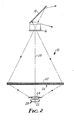
- FIGURE 2 is a schematic representation of the overhead projector 10 and illustrates an incandescent filament 22, preferably a tungsten filament of the commonly known "coiled-coil" type which radiates light over a wide distribution angle.
- Light emitted by the light source 22 is further controlled to cover the area of the stage 20 by a condensing lens 24 disposed between the filament 22 and the stage 20.
- the condensing lens 24 is preferably glass to resist heat generated by the filament 22.
- Between the glass stage 20 and the condensing lens 24 is a three-element annular Fresnel lens assembly 26 which refractively focuses light emitted to the filament 22 by the projection lens 16.
- the light source 22 is located much closer to the Fresnel lens assembly 26 than was previously thought possible. This results in increased illumination at the center of the Fresnel lens assembly 26, compared to the outer margins of the Fresnel lens assembly 26, due to the well-known "Cosine-fourth law".
- One method of increasing the light intensity at the margins of the Fresnel lens assembly 26 is by the use of an annular reflector 28, which may be a truncated sphere 30 as illustrated in FIGURE 4 or an annular Fresnel 32 reflector as illustrated in FIGURE 5. The center area of the annular reflector 28 is eliminated to prevent a contribution of reflected light to the central region of the Fresnel lens assembly 26.
- the filament 22, the center of the annular reflector 28, the center of the condensing lens 24, the center of the Fresnel lens assembly 26, the center of the glass stage 20 and the center of the projection lens 16 all are located along a common optical axis 34. It is with respect to this optical axis 34 that the radiation angle of light emitted by the light source 22 is measured, and it will be noted from FIGURE 2 that this radiation angle of light incident on the Fresnel lens assembly 26 varies from approximately 0° (along the optical axis 34) to in excess of 60°.
- the key component of the overhead projector 10 which permits the use of large radiation angles, and thus permits the filament 22 to be located very close to the stage 20 with a resulting drastic reduction in the height of the base 12, is the Fresnel lens assembly 26.
- the "speed" of a lens system is related to its f-number in that a lens system of a lesser f-number is considered to have a greater speed, i.e. be a "faster" lens system.
- the aperture "A” is the maximum diameter of Fresnel lens assembly 26 gathering light from the filament 22
- "D1” is the distance from the filament 22 to the Fresnel lens assembly 26
- "D2" is the distance from the Fresnel lens assembly 26 to its focal point at the projection lens 16.
- the Fresnel lens assembly 26 has been designed to have an f-number of preferably about 0.25, compared to an f-number of approximately 0.50 for conventional two Fresnel lens overhead projectors. Thus the distance from the filament 22 to the Fresnel lens assembly will be one-half that of conventional projectors, with a corresponding reduction in projector base height.
- the Fresnel lens assembly 26 of the present invention remains fully refractive (dioptric) in its focusing properties, and does not suffer from the sharp boundary change in transmission of a catadioptric Fresnel element.
- each additional lens element decreases the amount of light transmitted through the lens assembly 26. It is, therefore, desirable to use the least number of lens elements which will produce the required refraction characteristics. This number has been found to be three.
- FIGURE 3 illustrates in detail a portion of the Fresnel lens assembly 26 which includes a lower annular Fresnel lens 36, an intermediate annular Fresnel lens 38 and an upper annular Fresnel lens 40. "Upper” and “lower” refers to proximity of the Fresnel lens to the projection lens 16 and the filament 22, respectively.
- FIGURE 3 also illustrates a marginal light ray 42 from the filament 22 which impinges upon the lower Fresnel lens 36 at an angle of incidence of ⁇ , which angle ⁇ is equal to the radiation angle of the light ray 42 from the optical axis 34.
- the angle of light rays 42 at the margins of the Fresnel lens assembly 26 is preferably approximately 60°, although this angle may be larger if a further reduction in base height is desired.
- FIGURE 3 further illustrates an angle ⁇ which is the angle of refraction on the lower Fresnel element 36, an angle ⁇ which is the groove angle of each Fresnel element 36, 38 and 40, and an angle ⁇ which is the riser step angle of the Fresnel elements 36, 38 and 40.
- the groove frequency of the three Fresnel elements 36, 38 and 40 have a value of about two to eight grooves per millimeter and are preferably manufactured of acrylic optical plastic.
- the riser steps angles, ⁇ , of the lower Fresnel element 36 are controlled such that the risers remain parallel to the internally refracted ray 42, to minimize riser step blockage.
- the projection lens 16 is preferably of the variable focus type, in which image magnification changes are achieved by changing the focal length of the lens.
- the advantage to using this type of projection lens is that there is negligible movement of the projection lens over the focus range.
- the light source then can remain fixed in its closest position to the Fresnel lens assembly 26, keeping the height of the base 12 to a minimum.
- the distance of the filament 22 from the three-element Fresnel lens assembly 26 is 97 mm.
- the glass condenser lens 24 has a focal length of 275 mm.
- the reflector 28 is spherical with a radius of curvature of 23.9 mm and has an upper diameter of 44 mm and a lower diameter of 32 mm.
- the center of the spherical reflector 28 is located 23.9 mm below the filament 22.
- the Fresnel lens assembly 26 has a combined focal length of 79.82 mm and operates at an f-number of f/0.23.
- the riser step angles ⁇ for the lower Fresnel element 36 are controlled to vary from 89.9° near the center of the element 36 to 53.9° near the lens corner.
- the entire Fresnel lens assembly 26 is preferably sealed at its edges to protect the grooved surfaces. All Fresnel elements 36, 38 and 40 are manufactured in two millimeter thick optical acrylic plastic, having a refractive index of 1.491 for yellow light.
- the variable focal length projection lens has a focal length range of 280 mm to 315 mm and an f-number of f/6.5.
- the projection lens 16 can project images over the magnification range of 3.1 ⁇ to 9.8 ⁇ at a nominal height above the stage 20 of 378 mm.
Landscapes
- Physics & Mathematics (AREA)
- General Physics & Mathematics (AREA)
- Overhead Projectors And Projection Screens (AREA)
- Projection Apparatus (AREA)
Applications Claiming Priority (2)
| Application Number | Priority Date | Filing Date | Title |
|---|---|---|---|
| US06/944,425 US4741613A (en) | 1986-12-19 | 1986-12-19 | Reduced height transmissive overhead projector |
| US944425 | 1986-12-19 |
Publications (3)
| Publication Number | Publication Date |
|---|---|
| EP0272807A2 true EP0272807A2 (de) | 1988-06-29 |
| EP0272807A3 EP0272807A3 (en) | 1989-07-19 |
| EP0272807B1 EP0272807B1 (de) | 1993-07-21 |
Family
ID=25481374
Family Applications (1)
| Application Number | Title | Priority Date | Filing Date |
|---|---|---|---|
| EP87310370A Expired - Lifetime EP0272807B1 (de) | 1986-12-19 | 1987-11-25 | Transmissions-Overhead-Projektor mit reduzierter Höhe |
Country Status (11)
| Country | Link |
|---|---|
| US (1) | US4741613A (de) |
| EP (1) | EP0272807B1 (de) |
| JP (1) | JPS63165837A (de) |
| KR (1) | KR880008052A (de) |
| AU (1) | AU597751B2 (de) |
| BR (1) | BR8706817A (de) |
| CA (1) | CA1330894C (de) |
| DE (1) | DE3786652T2 (de) |
| HK (1) | HK76894A (de) |
| NO (1) | NO174645C (de) |
| YU (1) | YU232787A (de) |
Cited By (3)
| Publication number | Priority date | Publication date | Assignee | Title |
|---|---|---|---|---|
| WO1992022008A1 (en) * | 1991-06-07 | 1992-12-10 | Minnesota Mining And Manufacturing Company | Condenser lens system for overhead projector |
| DE9404793U1 (de) * | 1994-03-15 | 1994-08-25 | AV-Kommunikation Anders + Kern GmbH & Co KG, 22851 Norderstedt | Overheadprojektor |
| DE4443996A1 (de) * | 1994-12-10 | 1996-06-13 | Fraunhofer Ges Forschung | Projektor |
Families Citing this family (15)
| Publication number | Priority date | Publication date | Assignee | Title |
|---|---|---|---|---|
| DE3728191C1 (de) * | 1987-08-24 | 1989-02-23 | Medium Vertriebsgesellschaft F | Durchlicht-Schreibprojektor |
| US5208620A (en) * | 1988-10-04 | 1993-05-04 | Canon Kabushiki Kaisha | Display apparatus |
| US5296882A (en) * | 1992-12-21 | 1994-03-22 | Minnesota Mining And Manufacturing Company | Overhead projector with catadioptric fresnel lens |
| US5400094A (en) * | 1993-03-31 | 1995-03-21 | Minnesota Mining And Manufacturing Company | Condensers for overhead projectors |
| US5317349A (en) * | 1993-06-29 | 1994-05-31 | Minnesota Mining And Manufacturing Company | Overhead projector with achromatic fresnel lens |
| WO1995022772A1 (en) * | 1994-02-16 | 1995-08-24 | Minnesota Mining And Manufacturing Company | Dual grooved fresnel lens for overhead projection |
| US5515123A (en) * | 1994-02-17 | 1996-05-07 | Minnesota Mining And Manufacturing Company | Condensers for illumination systems |
| DE19737107C2 (de) * | 1997-08-26 | 2001-02-08 | Fresnel Optics Gmbh | Optische Anordnung bestehend aus mindestens zwei Fresnellinsen und Projektions- bzw. Displayvorrichtung mit dieser Anordnung |
| US6582084B2 (en) * | 2001-03-19 | 2003-06-24 | 3M Innovative Properties Company | Projector having an inverted head optical arrangement |
| US20080047605A1 (en) * | 2005-07-28 | 2008-02-28 | Regents Of The University Of California | Multi-junction solar cells with a homogenizer system and coupled non-imaging light concentrator |
| EP2122820A4 (de) * | 2007-02-23 | 2016-08-03 | Univ California | Photovoltaisches konzentrationssystem mit einer fresnel-linse und nichtabbildender sekundäroptik |
| US20090231739A1 (en) * | 2007-05-07 | 2009-09-17 | The Regents Of The University Of California A California Corporation | Matrix formulation of kohler integrating system and coupled non-imaging light concentrator |
| CN102282429A (zh) * | 2008-11-18 | 2011-12-14 | 光处方革新有限公司 | 科勒聚光器 |
| US9039213B2 (en) | 2009-07-30 | 2015-05-26 | The Regents Of The University Of California | Light concentration apparatus, systems and methods |
| US8684545B2 (en) | 2009-07-30 | 2014-04-01 | The Regents Of The University Of California | Light concentration apparatus, systems and methods |
Family Cites Families (9)
| Publication number | Priority date | Publication date | Assignee | Title |
|---|---|---|---|---|
| US3770344A (en) * | 1969-05-20 | 1973-11-06 | Ricoh Kk | Light source system for overhead projectors |
| US3653754A (en) * | 1969-12-29 | 1972-04-04 | Cabin Ind | Overhead projector |
| US3702395A (en) * | 1970-10-09 | 1972-11-07 | Us Navy | Condenser system for high intensity light source |
| JPS5243095B2 (de) * | 1973-08-03 | 1977-10-28 | ||
| US4118114A (en) * | 1974-08-21 | 1978-10-03 | Minnesota Mining And Manufacturing Company | Low-glare overhead projector |
| US4080052A (en) * | 1977-01-13 | 1978-03-21 | Gte Sylvania Incorporated | Overhead projection system with lens assembly having concentrically-oriented condensing lenses |
| JPS5560935A (en) * | 1978-10-31 | 1980-05-08 | Gakken Co Ltd | Overhead projector |
| US4436392A (en) * | 1983-01-03 | 1984-03-13 | Minnesota Mining And Manufacturing Company | Distortion correction for an overhead projector system |
| US4561740A (en) * | 1984-06-06 | 1985-12-31 | Minnesota Mining And Manufacturing Company | Dual-magnification rear projection lectern |
-
1986
- 1986-12-19 US US06/944,425 patent/US4741613A/en not_active Expired - Fee Related
-
1987
- 1987-11-23 AU AU81491/87A patent/AU597751B2/en not_active Ceased
- 1987-11-23 CA CA000552436A patent/CA1330894C/en not_active Expired - Fee Related
- 1987-11-25 EP EP87310370A patent/EP0272807B1/de not_active Expired - Lifetime
- 1987-11-25 DE DE87310370T patent/DE3786652T2/de not_active Expired - Fee Related
- 1987-12-15 BR BR8706817A patent/BR8706817A/pt not_active IP Right Cessation
- 1987-12-16 NO NO875274A patent/NO174645C/no unknown
- 1987-12-17 JP JP62320048A patent/JPS63165837A/ja active Pending
- 1987-12-18 YU YU02327/87A patent/YU232787A/xx unknown
- 1987-12-18 KR KR870014497A patent/KR880008052A/ko not_active Ceased
-
1994
- 1994-08-04 HK HK76894A patent/HK76894A/en unknown
Cited By (3)
| Publication number | Priority date | Publication date | Assignee | Title |
|---|---|---|---|---|
| WO1992022008A1 (en) * | 1991-06-07 | 1992-12-10 | Minnesota Mining And Manufacturing Company | Condenser lens system for overhead projector |
| DE9404793U1 (de) * | 1994-03-15 | 1994-08-25 | AV-Kommunikation Anders + Kern GmbH & Co KG, 22851 Norderstedt | Overheadprojektor |
| DE4443996A1 (de) * | 1994-12-10 | 1996-06-13 | Fraunhofer Ges Forschung | Projektor |
Also Published As
| Publication number | Publication date |
|---|---|
| NO875274L (no) | 1988-06-20 |
| CA1330894C (en) | 1994-07-26 |
| NO875274D0 (no) | 1987-12-16 |
| AU8149187A (en) | 1988-06-23 |
| BR8706817A (pt) | 1988-07-19 |
| YU232787A (en) | 1990-06-30 |
| HK76894A (en) | 1994-08-12 |
| US4741613A (en) | 1988-05-03 |
| DE3786652D1 (de) | 1993-08-26 |
| KR880008052A (ko) | 1988-08-30 |
| EP0272807A3 (en) | 1989-07-19 |
| EP0272807B1 (de) | 1993-07-21 |
| NO174645C (no) | 1994-06-08 |
| JPS63165837A (ja) | 1988-07-09 |
| DE3786652T2 (de) | 1994-01-05 |
| AU597751B2 (en) | 1990-06-07 |
| NO174645B (no) | 1994-02-28 |
Similar Documents
| Publication | Publication Date | Title |
|---|---|---|
| EP0272807B1 (de) | Transmissions-Overhead-Projektor mit reduzierter Höhe | |
| US6332688B1 (en) | Apparatus for uniformly illuminating a light valve | |
| US5089910A (en) | Infrared catadioptric zoom relay telescope with an asperic primary mirror | |
| US5296882A (en) | Overhead projector with catadioptric fresnel lens | |
| EP0706676B1 (de) | Overhead projektor mit achromatischer fresnellinse | |
| US4436393A (en) | Distortion correction for an overhead projector system | |
| CA1240862A (en) | Distortion correction for an overhead projector system | |
| EP0587671B1 (de) | Linsen-kondensor-system für einen overhead projektor | |
| US4867547A (en) | Mirror objective and optical arrangement comprising two mirror objectives | |
| EP0059193B1 (de) | Optisches system für projektionsapparate | |
| US5918968A (en) | Illuminating device for projector | |
| US5803568A (en) | Dual grooved Fresnel lens for overhead projection | |
| US4867555A (en) | Retrofocus lens for overhead projector | |
| NL8602974A (nl) | Projektielenzenstelsel. | |
| JPH03257444A (ja) | マイクロリーダプリンタの照明系 | |
| KR100319542B1 (ko) | 조명시스템용집광장치 | |
| JPH09270885A (ja) | 照明光学系 | |
| HK1006879B (en) | Overhead projector with achromatic fresnel lens | |
| JPS6115103A (ja) | 焦点合わせ用フレネルレンズ | |
| KR19980046757A (ko) | 카메라용 비구면 접안 단렌즈 | |
| HK1012725B (en) | Overhead projector with catadioptric fresnel lens |
Legal Events
| Date | Code | Title | Description |
|---|---|---|---|
| PUAI | Public reference made under article 153(3) epc to a published international application that has entered the european phase |
Free format text: ORIGINAL CODE: 0009012 |
|
| AK | Designated contracting states |
Kind code of ref document: A2 Designated state(s): CH DE FR GB IT LI NL SE |
|
| PUAL | Search report despatched |
Free format text: ORIGINAL CODE: 0009013 |
|
| AK | Designated contracting states |
Kind code of ref document: A3 Designated state(s): CH DE FR GB IT LI NL SE |
|
| 17P | Request for examination filed |
Effective date: 19900102 |
|
| 17Q | First examination report despatched |
Effective date: 19920121 |
|
| ITF | It: translation for a ep patent filed | ||
| GRAA | (expected) grant |
Free format text: ORIGINAL CODE: 0009210 |
|
| AK | Designated contracting states |
Kind code of ref document: B1 Designated state(s): CH DE FR GB IT LI NL SE |
|
| REF | Corresponds to: |
Ref document number: 3786652 Country of ref document: DE Date of ref document: 19930826 |
|
| ET | Fr: translation filed | ||
| PLBE | No opposition filed within time limit |
Free format text: ORIGINAL CODE: 0009261 |
|
| STAA | Information on the status of an ep patent application or granted ep patent |
Free format text: STATUS: NO OPPOSITION FILED WITHIN TIME LIMIT |
|
| 26N | No opposition filed | ||
| EAL | Se: european patent in force in sweden |
Ref document number: 87310370.9 |
|
| PGFP | Annual fee paid to national office [announced via postgrant information from national office to epo] |
Ref country code: FR Payment date: 19951013 Year of fee payment: 9 |
|
| PGFP | Annual fee paid to national office [announced via postgrant information from national office to epo] |
Ref country code: SE Payment date: 19951016 Year of fee payment: 9 |
|
| PGFP | Annual fee paid to national office [announced via postgrant information from national office to epo] |
Ref country code: CH Payment date: 19951019 Year of fee payment: 9 |
|
| PGFP | Annual fee paid to national office [announced via postgrant information from national office to epo] |
Ref country code: NL Payment date: 19951024 Year of fee payment: 9 |
|
| PGFP | Annual fee paid to national office [announced via postgrant information from national office to epo] |
Ref country code: GB Payment date: 19951026 Year of fee payment: 9 |
|
| PGFP | Annual fee paid to national office [announced via postgrant information from national office to epo] |
Ref country code: DE Payment date: 19951027 Year of fee payment: 9 |
|
| PG25 | Lapsed in a contracting state [announced via postgrant information from national office to epo] |
Ref country code: GB Effective date: 19961125 |
|
| PG25 | Lapsed in a contracting state [announced via postgrant information from national office to epo] |
Ref country code: SE Effective date: 19961126 |
|
| PG25 | Lapsed in a contracting state [announced via postgrant information from national office to epo] |
Ref country code: LI Effective date: 19961130 Ref country code: CH Effective date: 19961130 |
|
| PG25 | Lapsed in a contracting state [announced via postgrant information from national office to epo] |
Ref country code: NL Effective date: 19970601 |
|
| REG | Reference to a national code |
Ref country code: CH Ref legal event code: PL |
|
| GBPC | Gb: european patent ceased through non-payment of renewal fee |
Effective date: 19961125 |
|
| PG25 | Lapsed in a contracting state [announced via postgrant information from national office to epo] |
Ref country code: FR Effective date: 19970731 |
|
| NLV4 | Nl: lapsed or anulled due to non-payment of the annual fee |
Effective date: 19970601 |
|
| PG25 | Lapsed in a contracting state [announced via postgrant information from national office to epo] |
Ref country code: DE Effective date: 19970801 |
|
| EUG | Se: european patent has lapsed |
Ref document number: 87310370.9 |
|
| REG | Reference to a national code |
Ref country code: FR Ref legal event code: ST |
|
| PG25 | Lapsed in a contracting state [announced via postgrant information from national office to epo] |
Ref country code: IT Free format text: LAPSE BECAUSE OF NON-PAYMENT OF DUE FEES;WARNING: LAPSES OF ITALIAN PATENTS WITH EFFECTIVE DATE BEFORE 2007 MAY HAVE OCCURRED AT ANY TIME BEFORE 2007. THE CORRECT EFFECTIVE DATE MAY BE DIFFERENT FROM THE ONE RECORDED. Effective date: 20051125 |