EP0272571A2 - Roll stand with roll rings - Google Patents
Roll stand with roll rings Download PDFInfo
- Publication number
- EP0272571A2 EP0272571A2 EP87118456A EP87118456A EP0272571A2 EP 0272571 A2 EP0272571 A2 EP 0272571A2 EP 87118456 A EP87118456 A EP 87118456A EP 87118456 A EP87118456 A EP 87118456A EP 0272571 A2 EP0272571 A2 EP 0272571A2
- Authority
- EP
- European Patent Office
- Prior art keywords
- piston
- cylinder units
- roll
- bearing housings
- pressure
- Prior art date
- Legal status (The legal status is an assumption and is not a legal conclusion. Google has not performed a legal analysis and makes no representation as to the accuracy of the status listed.)
- Granted
Links
- 238000005096 rolling process Methods 0.000 claims abstract description 24
- 238000006073 displacement reaction Methods 0.000 claims description 5
- 230000000284 resting effect Effects 0.000 claims 2
- 238000012544 monitoring process Methods 0.000 claims 1
- 238000000034 method Methods 0.000 description 3
- 230000001105 regulatory effect Effects 0.000 description 3
- 238000003825 pressing Methods 0.000 description 2
- 238000010276 construction Methods 0.000 description 1
- 230000001276 controlling effect Effects 0.000 description 1
- 238000013016 damping Methods 0.000 description 1
- 238000010586 diagram Methods 0.000 description 1
- 230000000694 effects Effects 0.000 description 1
- 230000005489 elastic deformation Effects 0.000 description 1
Images


Classifications
-
- B—PERFORMING OPERATIONS; TRANSPORTING
- B21—MECHANICAL METAL-WORKING WITHOUT ESSENTIALLY REMOVING MATERIAL; PUNCHING METAL
- B21B—ROLLING OF METAL
- B21B13/00—Metal-rolling stands, i.e. an assembly composed of a stand frame, rolls, and accessories
-
- B—PERFORMING OPERATIONS; TRANSPORTING
- B21—MECHANICAL METAL-WORKING WITHOUT ESSENTIALLY REMOVING MATERIAL; PUNCHING METAL
- B21B—ROLLING OF METAL
- B21B37/00—Control devices or methods specially adapted for metal-rolling mills or the work produced thereby
- B21B37/58—Roll-force control; Roll-gap control
- B21B37/62—Roll-force control; Roll-gap control by control of a hydraulic adjusting device
-
- B—PERFORMING OPERATIONS; TRANSPORTING
- B21—MECHANICAL METAL-WORKING WITHOUT ESSENTIALLY REMOVING MATERIAL; PUNCHING METAL
- B21B—ROLLING OF METAL
- B21B13/00—Metal-rolling stands, i.e. an assembly composed of a stand frame, rolls, and accessories
- B21B13/005—Cantilevered roll stands
-
- B—PERFORMING OPERATIONS; TRANSPORTING
- B21—MECHANICAL METAL-WORKING WITHOUT ESSENTIALLY REMOVING MATERIAL; PUNCHING METAL
- B21B—ROLLING OF METAL
- B21B31/00—Rolling stand structures; Mounting, adjusting, or interchanging rolls, roll mountings, or stand frames
- B21B31/02—Rolling stand frames or housings; Roll mountings ; Roll chocks
- B21B31/04—Rolling stand frames or housings; Roll mountings ; Roll chocks with tie rods in frameless stands, e.g. prestressed tie rods
-
- B—PERFORMING OPERATIONS; TRANSPORTING
- B21—MECHANICAL METAL-WORKING WITHOUT ESSENTIALLY REMOVING MATERIAL; PUNCHING METAL
- B21B—ROLLING OF METAL
- B21B31/00—Rolling stand structures; Mounting, adjusting, or interchanging rolls, roll mountings, or stand frames
- B21B31/16—Adjusting or positioning rolls
- B21B31/20—Adjusting or positioning rolls by moving rolls perpendicularly to roll axis
- B21B31/32—Adjusting or positioning rolls by moving rolls perpendicularly to roll axis by liquid pressure, e.g. hydromechanical adjusting
-
- B—PERFORMING OPERATIONS; TRANSPORTING
- B21—MECHANICAL METAL-WORKING WITHOUT ESSENTIALLY REMOVING MATERIAL; PUNCHING METAL
- B21B—ROLLING OF METAL
- B21B31/00—Rolling stand structures; Mounting, adjusting, or interchanging rolls, roll mountings, or stand frames
- B21B31/08—Interchanging rolls, roll mountings, or stand frames, e.g. using C-hooks; Replacing roll chocks on roll shafts
Definitions
- the present invention relates to a roll stand with roll rings which are placed from one side or in a cantilevered manner on a pair of adjustable roll support shafts which are supported on two sides.
- Both roll support shafts have extension journals which project beyond the roll rings.
- Journal bearings can be slid onto and are fixable on the extension journals.
- the journal bearings have bearing housings which are connected with each other in a frictionally engaging manner for absorbing rolling forces by means of piston-cylinder units which can be actuated by a pressure medium and are movable parallel to the direction of adjustment of the roll support shafts, wherein one of the bearing housings is connected to the piston rods of the piston-cylinder unit and the other bearing housing, which supports the piston-cylinder unit, has sliding guide means for these piston rods.
- Roll stands of this type can absorb substantially greater rolling forces than roll stands which do not have the bearing housings for the journal bearings which can be slid onto and fixed on the extension journals.
- the pressure-actuated piston-cylinder units connected to the bearing housings make it possible to absorb a substantial portion of the rolling forces when the roll rings are supported from one side. In the past, this had only been possible when the roll or roll rings had been supported on two sides on both sides of the roll or roll ring in normal roll stands having two roll housings connected by means of transverse support members.
- both journal portions of the roll support shafts which carry the rolls resiliently return by a certain distance toward the roll gap after the end of the rolling stock section has left the roll gap, so that the effect of the above-described impacts is further increased.
- the primary object of the present invention to provide a roll stand in which the above-described disadvantages are avoided and, consequently, the stiffness of the roll stand is increased.
- the roll stand of the type described above includes additional piston-cylinder units arranged between the two bearing housings.
- the cylinders and pistons of the additional piston-cylinder units are guided by the piston rods of the other piston-cylinder units which connect the bearing housings.
- the pistons of the additional piston-cylinder units rest against one of the two bearing housings and the cylinders of the additional piston-cylinder units rest against the other of the bearing housings. Pressure can be applied to the additional piston-cylinder units independently of the other piston-cylinder units.
- the piston-cylinder units whose piston rods connect the two bearing housings and the piston-cylinder units which are arranged between the bearing housings have the same working surface areas and are connected to a common pressure generating unit, but the pressure acting on the respective piston-cylinder units is individually adjustable and the respective piston-cylinder units can be individually separated from the pressure generating unit and can be closed individually.
- a displacement pickup may be provided which monitors the spacing between the bearing housings and which is capable of influencing a position adjusting and controlling device for the piston-cylinder units whose piston-rods connect the bearing housings.
- the piston-cylinder units arranged between the bearing housings may be pairs of axially spaced apart piston-cylinder units which can be actuated simultaneously and together with pressure.
- the piston-cylinder units may be arranged in a roll housing which is rigidly connected to the roll stand, wherein the bearing housings define recesses which are open toward the roll stand and surround the cylinders and the piston rods of the piston-cylinder units and which define contact seat surfaces for the cylinders and/or the pistons of the piston-cylinder units and include releasable fixing elements for the latter.
- the two bearing housings can be pretensioned against the rolling pressure as is the case in known constructions for keeping constant the adjusted width of the rolling gap, while, by applying pressure to the piston-cylinder units whose piston rods connect the bearing housings as well as to the piston-cylinder units which are arranged between the bearing housings, a bracing of the bearing housings can be achieved which corresponds to a bracing which is achievable by screws.
- the piston rods expand and cause a corresponding decrease of the pressure in the piston-cylinder units arranged between the bearing housings.
- the adjustment movements of the bearing housings are carried out with positive balancing, wherein the pretensioning of the bearing housings relative to each other is maintained, i.e., the piston rods remain under tensile load and the piston-cylinder units arranged between the bearing housings exert a pressure on both bearing housings.
- This pressure further means that the bearing play of the journal portions of the roll support shafts can be eliminated when the piston-cylinder units arranged between the bearing housings are dimensioned in such a way that the pressure generated by these units on the bearing housings is slightly greater than the tensioning pressure exerted by the piston-cylinder units connecting the bearing housings and, consequently, a positive balancing of the bearing housings is achieved.
- bearing housings or chocks 2 and 3 which receive journal portions 1a of roll support shafts 1 are connected through piston rods 4a of piston-cylinder units 4.
- An end face of a cylinder 4b of each piston-cylinder unit 4 rests on one of the bearing housings 2.
- Piston rods 4a extend through a bore 2a of this bearing housing and through another bore 3a of the bearing housing 3 and are fixed by means of screws 5.
- Additional piston-cylinder units 6 are arranged between the bearing housings 2 and 3. As illustrated in the drawing, the end face of the piston 6c of each piston-cylinder unit 6 rests against the bearing housing 2 and an end face of cylinder 6b rests against the other bearing housing 3.
- cylinder 6b The outer surface of cylinder 6b is slidingly guided in guide means 2b of the bearing housing 2; also, cylinder 6b and piston 6c of this piston-cylinder unit slides on the piston rod 4a of piston-cylinder unit 4 which piston rod 4a extends centrally through appropriate bores provided in piston-cylinder unit 6.
- pairs of piston-cylinder units are arranged between the bearing housings 2 and 3 axially spaced apart by a distance D.
- the pairs of piston-cylinder units are arranged in a support frame 7 which is illustrated in dash-dotted lines. This arrangement makes it possible to use piston-cylinder units with short strokes even if the width of the roll gap is great.
- Fig. 5 of the drawing shows that, in the embodiment of Figs. 3 and 4, the bearing housings 2 and 3 have recesses with contact seat surfaces 3d, which recesses are open toward the roll stand 8 and surround the cylinders 4b and 6b ⁇ and 6b ⁇ and the piston rods 4a of the piston-cylinder units 4.
- These recesses make it possible to remove the bearing housings 2 and 3 together with the roll rings 10 from the journal portions 1a of the oll support shafts 1, without having to separate the connection of the piston-cylinder units 4 and 6 with the support frame 7.
- the piston-cylinder units 4 and 6 as well as the support frame 7 remain connected to the roll stand 8.
- roll ring 10 is supported by a sleeve-like extension 11a of an inner ring 11 of journal bearing 12.
- the pressure to be applied is generated by a pump 21 secured by a pressure relief valve 22.
- a magnet b of a solenoid valve 28 applies pressure to the piston-cylinder unit 6.
- the pressure is regulated at pressure-reducing valve 26.
- a possibility for relief is provided for a hydraulically controlled check valve 20 via a directional control valve 13.
- a pressure increase due to mass and spring forces which occur when the rolling stock section leaves the roll gap can be limited by means of the damping reservoir 14.
- Pressure is applied to the piston-cylinder units 4 by actuating magnet b of solenoid valve 27, the pressure regulation being carried out at pressure-reducing valve 25.
- a possibility for relief is provided by a hydraulically controlled check valve 29 via directional control valve 15. Any pressure increase occurring during rolling can be limited by means of pressure relief valve 16.
- a possibility for additional intake is provided by means of check valve 17 when the rolling stock section leaves the rolling gap.
- a pressure application to piston-cylinder units 6 acts to bridge the bearing play and a pressure application to piston-cylinder units 4 acts to create the pretension through piston rods 4a.
- the hydraulically controlled check valves 29 and 20 serve to maintain the respectively adjusted pressure within the piston-cylinder units and the pretensioned pressure medium volumes act as stacks of springs would. After each pass, the piston-cylinder units 4 and 6 are relieved by opening the hydraulically controlled check valves 29 and 20; subsequently, the above-described procedure is repeated.
- a displacement pickup which monitors the spacing between the bearing housings 2 and 3 and position adjustment and control devices for the piston-cylinder units 4 which devices are influenced by the displacement pickup can be used for regulating the operation if valve 27 is replaced by a power-assisted valve and a pressure reservoir is arranged in the feedline to this pressure-assisted valve. In this case, pressure valve 25 is omitted.
- the power-assisted valve is used for regulating the pressure in the piston-cylinder unit 4 in accordance with the requirements, i.e., the device can compensate displacement errors caused during rolling, for example, by elastic deformations.
Abstract
Description
- The present invention relates to a roll stand with roll rings which are placed from one side or in a cantilevered manner on a pair of adjustable roll support shafts which are supported on two sides. Both roll support shafts have extension journals which project beyond the roll rings. Journal bearings can be slid onto and are fixable on the extension journals. The journal bearings have bearing housings which are connected with each other in a frictionally engaging manner for absorbing rolling forces by means of piston-cylinder units which can be actuated by a pressure medium and are movable parallel to the direction of adjustment of the roll support shafts, wherein one of the bearing housings is connected to the piston rods of the piston-cylinder unit and the other bearing housing, which supports the piston-cylinder unit, has sliding guide means for these piston rods.
- Roll stands of this type, even though the roll rings are supported in a cantilevering mass, can absorb substantially greater rolling forces than roll stands which do not have the bearing housings for the journal bearings which can be slid onto and fixed on the extension journals. The pressure-actuated piston-cylinder units connected to the bearing housings make it possible to absorb a substantial portion of the rolling forces when the roll rings are supported from one side. In the past, this had only been possible when the roll or roll rings had been supported on two sides on both sides of the roll or roll ring in normal roll stands having two roll housings connected by means of transverse support members. Thus, it is made possible to use the arrangement of roll rings from one side even in those cases in which significantly greater rolling forces occur than, for example, in wire finishing blocks, without increasing the bearing sizes and, consequently, the roll diameters.
- In addition, it is possible to use roll stands having especially great stiffnesses, such as, those with eccentric sleeve adjustment. Also, since such roll stands have relatively small dimensions, the roll stands can be placed more closely together in rolling direction. The resulting compact arrangement makes it easier to modernize existing rolling trains where space is limited.
- However, in the practical operation of such roll stands in rolling trains, as disclosed in German Offenlegungsschrift 34 07 207, it has been found that, when the rolling stock section enters the roll gap, the rolling stock section forces one or both bearing houses outwardly away from the rolling gap by a distance corresponding to the bearing play between the bearing housing and the journal portion of the roll support shaft, and that, after the end of the rolling stock section has left the roll gap, the bearing housing or housings return into their original position as a result of their weight. This process leads to undesirable impacts.
- In addition, due to the elasticity of the roll support shafts themselves and of the structural components of the system for applying pressure thereon, both journal portions of the roll support shafts which carry the rolls resiliently return by a certain distance toward the roll gap after the end of the rolling stock section has left the roll gap, so that the effect of the above-described impacts is further increased.
- It is, therefore, the primary object of the present invention to provide a roll stand in which the above-described disadvantages are avoided and, consequently, the stiffness of the roll stand is increased.
- In accordance with the present invention, the roll stand of the type described above includes additional piston-cylinder units arranged between the two bearing housings. The cylinders and pistons of the additional piston-cylinder units are guided by the piston rods of the other piston-cylinder units which connect the bearing housings. The pistons of the additional piston-cylinder units rest against one of the two bearing housings and the cylinders of the additional piston-cylinder units rest against the other of the bearing housings. Pressure can be applied to the additional piston-cylinder units independently of the other piston-cylinder units.
- In accordance with a feature of the present invention, the piston-cylinder units whose piston rods connect the two bearing housings and the piston-cylinder units which are arranged between the bearing housings have the same working surface areas and are connected to a common pressure generating unit, but the pressure acting on the respective piston-cylinder units is individually adjustable and the respective piston-cylinder units can be individually separated from the pressure generating unit and can be closed individually.
- In accordance with another feature of the present invention, a displacement pickup may be provided which monitors the spacing between the bearing housings and which is capable of influencing a position adjusting and controlling device for the piston-cylinder units whose piston-rods connect the bearing housings.
- In accordance with another feature of the present invention, the piston-cylinder units arranged between the bearing housings may be pairs of axially spaced apart piston-cylinder units which can be actuated simultaneously and together with pressure.
- Finally, the invention provides that the piston-cylinder units may be arranged in a roll housing which is rigidly connected to the roll stand, wherein the bearing housings define recesses which are open toward the roll stand and surround the cylinders and the piston rods of the piston-cylinder units and which define contact seat surfaces for the cylinders and/or the pistons of the piston-cylinder units and include releasable fixing elements for the latter.
- In such a roll stand according to the present invention, the two bearing housings can be pretensioned against the rolling pressure as is the case in known constructions for keeping constant the adjusted width of the rolling gap, while, by applying pressure to the piston-cylinder units whose piston rods connect the bearing housings as well as to the piston-cylinder units which are arranged between the bearing housings, a bracing of the bearing housings can be achieved which corresponds to a bracing which is achievable by screws. In other words, when the pressure in the piston-cylinder unit whose piston rods connect the bearing housings increases due to the rolling pressure, the piston rods expand and cause a corresponding decrease of the pressure in the piston-cylinder units arranged between the bearing housings. This be achieved in a structurally simple manner making it possible that, before the rolling stock section enters the roll gap, the piston-cylinder units whose piston rods connect the bearing housings and the piston-cylinder units arranged between the bearing housings can be separated from the common pressure generating unit and can be closed individually.
- On the other hand, prior to beginning rolling and when the appropriate pressure is applied to all piston-cylinder units, the adjustment movements of the bearing housings are carried out with positive balancing, wherein the pretensioning of the bearing housings relative to each other is maintained, i.e., the piston rods remain under tensile load and the piston-cylinder units arranged between the bearing housings exert a pressure on both bearing housings. This pressure further means that the bearing play of the journal portions of the roll support shafts can be eliminated when the piston-cylinder units arranged between the bearing housings are dimensioned in such a way that the pressure generated by these units on the bearing housings is slightly greater than the tensioning pressure exerted by the piston-cylinder units connecting the bearing housings and, consequently, a positive balancing of the bearing housings is achieved.
- The various features of novelty which characterize the invention are pointed out with particularity in the claims annexed to and forming a part of this disclosure. For a better understanding of the invention, its operating advantages and specific objects attained by its use, reference should be had to the drawings and descriptive matter in which there are illustrated and described preferred embodiments of the invention.
- In the drawing:
- Fig. 1 is a front elevational view, partly in section, of a roll stand with an arrangement of bearing housings with piston-cylinder units according to the present invention;
- Fig. 2 is a side view, also partly in section, of the roll stand of Fig. 1;
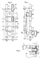
- Fig. 3 is a front elevational view, partly in section, of another embodiment of the roll stand according to the present invention;
- Fig 4 is a side view of the roll stand of Fig. 3;
- Fig. 5 is a sectional view taken along sectional line A-A of Fig. 4; and
- Fig. 6 is a hydraulic diagram of a pressure medium control device for operating the roll stand according to the present invention.
- As illustrated in Figs. 1 and 2 of the drawing, bearing housings or
chocks journal portions 1a of roll support shafts 1 are connected throughpiston rods 4a of piston-cylinder units 4. An end face of acylinder 4b of each piston-cylinder unit 4 rests on one of the bearinghousings 2. Pistonrods 4a extend through abore 2a of this bearing housing and through anotherbore 3a of the bearinghousing 3 and are fixed by means ofscrews 5. Additional piston-cylinder units 6 are arranged between the bearinghousings piston 6c of each piston-cylinder unit 6 rests against the bearinghousing 2 and an end face ofcylinder 6b rests against the other bearinghousing 3. The outer surface ofcylinder 6b is slidingly guided in guide means 2b of the bearinghousing 2; also,cylinder 6b andpiston 6c of this piston-cylinder unit slides on thepiston rod 4a of piston-cylinder unit 4 whichpiston rod 4a extends centrally through appropriate bores provided in piston-cylinder unit 6. - In the embodiment illustrated in Figs. 3 and 4 of the drawing, pairs of piston-cylinder units are arranged between the bearing
housings support frame 7 which is illustrated in dash-dotted lines. This arrangement makes it possible to use piston-cylinder units with short strokes even if the width of the roll gap is great. - Fig. 5 of the drawing shows that, in the embodiment of Figs. 3 and 4, the bearing
housings contact seat surfaces 3d, which recesses are open toward the roll stand 8 and surround thecylinders 4b and 6bʹ and 6bʺ and thepiston rods 4a of the piston-cylinder units 4. These recesses make it possible to remove the bearinghousings roll rings 10 from thejournal portions 1a of the oll support shafts 1, without having to separate the connection of the piston-cylinder units 4 and 6 with thesupport frame 7. The piston-cylinder units 4 and 6 as well as thesupport frame 7 remain connected to the roll stand 8. During this procedure,roll ring 10 is supported by a sleeve-like extension 11a of aninner ring 11 of journal bearing 12. - The operation of the pressure medium control device for the piston-cylinder unit shall now be explained with the aid of Fig. 6.
- The pressure to be applied is generated by a
pump 21 secured by apressure relief valve 22. A magnet b of asolenoid valve 28 applies pressure to the piston-cylinder unit 6. The pressure is regulated at pressure-reducing valve 26. A possibility for relief is provided for a hydraulically controlledcheck valve 20 via adirectional control valve 13. A pressure increase due to mass and spring forces which occur when the rolling stock section leaves the roll gap can be limited by means of thedamping reservoir 14. - Pressure is applied to the piston-cylinder units 4 by actuating magnet b of
solenoid valve 27, the pressure regulation being carried out at pressure-reducingvalve 25. A possibility for relief is provided by a hydraulically controlledcheck valve 29 viadirectional control valve 15. Any pressure increase occurring during rolling can be limited by means ofpressure relief valve 16. A possibility for additional intake is provided by means ofcheck valve 17 when the rolling stock section leaves the rolling gap. - When operation is started, a pressure application to piston-
cylinder units 6 acts to bridge the bearing play and a pressure application to piston-cylinder units 4 acts to create the pretension throughpiston rods 4a. The hydraulically controlledcheck valves cylinder units 4 and 6 are relieved by opening the hydraulically controlledcheck valves - A displacement pickup which monitors the spacing between the bearing
housings valve 27 is replaced by a power-assisted valve and a pressure reservoir is arranged in the feedline to this pressure-assisted valve. In this case,pressure valve 25 is omitted. The power-assisted valve is used for regulating the pressure in the piston-cylinder unit 4 in accordance with the requirements, i.e., the device can compensate displacement errors caused during rolling, for example, by elastic deformations. - While specific embodiments of the invention have been shown and described in detail to illustrate the application of the inventive principles, it will be understood that the invention may be embodied otherwise without departing from such principles.
Claims (5)
Priority Applications (1)
| Application Number | Priority Date | Filing Date | Title |
|---|---|---|---|
| AT87118456T ATE65195T1 (en) | 1986-12-16 | 1987-12-12 | ROLLING STAND WITH ROLLING RINGS. |
Applications Claiming Priority (2)
| Application Number | Priority Date | Filing Date | Title |
|---|---|---|---|
| DE3642903 | 1986-12-16 | ||
| DE19863642903 DE3642903A1 (en) | 1986-12-16 | 1986-12-16 | ROLLING MILLS WITH ROLLER RINGS INSTALLED ON ONE SIDE ON A DOUBLE-SIDED ROLLER SUPPORT SHAFT |
Publications (3)
| Publication Number | Publication Date |
|---|---|
| EP0272571A2 true EP0272571A2 (en) | 1988-06-29 |
| EP0272571A3 EP0272571A3 (en) | 1988-11-17 |
| EP0272571B1 EP0272571B1 (en) | 1991-07-17 |
Family
ID=6316284
Family Applications (1)
| Application Number | Title | Priority Date | Filing Date |
|---|---|---|---|
| EP87118456A Expired - Lifetime EP0272571B1 (en) | 1986-12-16 | 1987-12-12 | Roll stand with roll rings |
Country Status (8)
| Country | Link |
|---|---|
| US (1) | US4920778A (en) |
| EP (1) | EP0272571B1 (en) |
| JP (1) | JPS63160706A (en) |
| KR (1) | KR880007141A (en) |
| CN (1) | CN1011666B (en) |
| AT (1) | ATE65195T1 (en) |
| DE (2) | DE3642903A1 (en) |
| ES (1) | ES2023177B3 (en) |
Cited By (2)
| Publication number | Priority date | Publication date | Assignee | Title |
|---|---|---|---|---|
| CN101648262B (en) * | 2009-08-29 | 2012-01-11 | 湖南九一连续铸轧实业有限责任公司 | Puller resetting device on shifting bearing block of twin-roll cast-rolling mill |
| CN103203624A (en) * | 2013-04-28 | 2013-07-17 | 苏州工业园区高登威科技有限公司 | Cylinder control device |
Families Citing this family (9)
| Publication number | Priority date | Publication date | Assignee | Title |
|---|---|---|---|---|
| SE502125C2 (en) * | 1993-12-02 | 1995-08-28 | Valmet Karlstad Ab | Compact rack for a press in a paper or cardboard machine |
| FI107463B (en) * | 1996-06-05 | 2001-08-15 | Metso Paper Inc | Coupling structure between the long nip roll and its counter roll |
| AUPQ120999A0 (en) * | 1999-06-25 | 1999-07-22 | Industrial Automation Services Pty Ltd | Vibration suppressing piston |
| TWI271225B (en) * | 2002-05-29 | 2007-01-21 | Sms Demag Ag | Apparatus for controlled influencing of the supporting forces of backing rollers |
| CN101716600B (en) * | 2010-01-06 | 2011-09-21 | 张晓玲 | Roller bases of section mill |
| CN102114586A (en) * | 2010-12-22 | 2011-07-06 | 中国第一汽车集团公司 | Pneumatic combination method and device of multiposition switching |
| CN102825630B (en) * | 2012-08-29 | 2015-09-16 | 三明市普诺维机械有限公司 | High speed roller pressing die-cutting rule mould bases |
| CN106424132B (en) * | 2016-10-27 | 2019-04-05 | 天津市中重科技工程有限公司 | A kind of prestressing force universal mill for H profile steel production |
| CN109530448A (en) * | 2018-10-29 | 2019-03-29 | 中冶陕压重工设备有限公司 | Operation roll of mill roller structure |
Citations (4)
| Publication number | Priority date | Publication date | Assignee | Title |
|---|---|---|---|---|
| AT181483B (en) * | 1949-07-12 | 1955-03-25 | Elin Ag Elek Ind Wien | Roller bracket for the storage of the forming rollers of pipe rolling and pipe welding machines |
| DE2323768B1 (en) * | 1973-05-11 | 1974-10-10 | Th. Kieserling & Albrecht, 5650 Solingen | Roll stand with exchangeably arranged rolls |
| DE2247622B2 (en) * | 1972-06-20 | 1976-04-15 | Pomini Farrel S.p.A., Castellanza. Varese (Italien) | ROLLING STAND FOR CONTINUOUSLY OPERATING SINGLE BLOCK ROLLING MILL WITH TWO ROLLERS |
| DE3407207A1 (en) * | 1984-02-28 | 1985-08-29 | SMS Schloemann-Siemag AG, 4000 Düsseldorf | Roll stand with roll rings mounted at one end (overhung) on a pair of roll supporting shafts |
Family Cites Families (10)
| Publication number | Priority date | Publication date | Assignee | Title |
|---|---|---|---|---|
| DE1198774B (en) * | 1960-11-21 | 1965-08-19 | Schloemann Ag | Roll bearings for rolling mills, especially duo rolling mills |
| FR94952E (en) * | 1961-12-01 | 1970-02-27 | Spidem Ste Nle | Reverse clamping prestressed rolling mill. |
| DE1287543B (en) * | 1964-01-15 | 1969-01-23 | Verwaltungsgesellschaft Moelle | Rolling frame with tie rods absorbing the rolling pressure and a hydraulic tensioning device for controlled stretching of the tie rod length during rolling |
| GB1183573A (en) * | 1966-06-03 | 1970-03-11 | Davy & United Eng Co Ltd | Rolling Mills |
| FR2036826A1 (en) * | 1969-04-04 | 1970-12-31 | Spidem Ste Nle | Compensating bending in multi-roll rolling - mills |
| JPS5035902B2 (en) * | 1972-05-17 | 1975-11-19 | ||
| GB1425915A (en) * | 1972-06-22 | 1976-02-25 | British Steel Corp | Rolling mills |
| FR2212185B3 (en) * | 1972-12-30 | 1976-10-15 | Siemag Siegener Masch Bau | |
| US4194383A (en) * | 1978-06-22 | 1980-03-25 | Gulf & Western Manufacturing Company | Modular transducer assembly for rolling mill roll adjustment mechanism |
| DE3574463D1 (en) * | 1984-04-28 | 1990-01-04 | Schloemann Siemag Ag | ROLLING MILLS. |
-
1986
- 1986-12-16 DE DE19863642903 patent/DE3642903A1/en not_active Withdrawn
-
1987
- 1987-12-12 AT AT87118456T patent/ATE65195T1/en active
- 1987-12-12 ES ES87118456T patent/ES2023177B3/en not_active Expired - Lifetime
- 1987-12-12 DE DE8787118456T patent/DE3771463D1/en not_active Expired - Lifetime
- 1987-12-12 EP EP87118456A patent/EP0272571B1/en not_active Expired - Lifetime
- 1987-12-15 JP JP62315405A patent/JPS63160706A/en active Pending
- 1987-12-15 KR KR870014329A patent/KR880007141A/en not_active Application Discontinuation
- 1987-12-16 US US07/133,292 patent/US4920778A/en not_active Expired - Fee Related
- 1987-12-16 CN CN87105966A patent/CN1011666B/en not_active Expired
Patent Citations (4)
| Publication number | Priority date | Publication date | Assignee | Title |
|---|---|---|---|---|
| AT181483B (en) * | 1949-07-12 | 1955-03-25 | Elin Ag Elek Ind Wien | Roller bracket for the storage of the forming rollers of pipe rolling and pipe welding machines |
| DE2247622B2 (en) * | 1972-06-20 | 1976-04-15 | Pomini Farrel S.p.A., Castellanza. Varese (Italien) | ROLLING STAND FOR CONTINUOUSLY OPERATING SINGLE BLOCK ROLLING MILL WITH TWO ROLLERS |
| DE2323768B1 (en) * | 1973-05-11 | 1974-10-10 | Th. Kieserling & Albrecht, 5650 Solingen | Roll stand with exchangeably arranged rolls |
| DE3407207A1 (en) * | 1984-02-28 | 1985-08-29 | SMS Schloemann-Siemag AG, 4000 Düsseldorf | Roll stand with roll rings mounted at one end (overhung) on a pair of roll supporting shafts |
Cited By (2)
| Publication number | Priority date | Publication date | Assignee | Title |
|---|---|---|---|---|
| CN101648262B (en) * | 2009-08-29 | 2012-01-11 | 湖南九一连续铸轧实业有限责任公司 | Puller resetting device on shifting bearing block of twin-roll cast-rolling mill |
| CN103203624A (en) * | 2013-04-28 | 2013-07-17 | 苏州工业园区高登威科技有限公司 | Cylinder control device |
Also Published As
| Publication number | Publication date |
|---|---|
| ES2023177B3 (en) | 1992-01-01 |
| CN87105966A (en) | 1988-09-28 |
| DE3771463D1 (en) | 1991-08-22 |
| EP0272571A3 (en) | 1988-11-17 |
| ATE65195T1 (en) | 1991-08-15 |
| KR880007141A (en) | 1988-08-26 |
| JPS63160706A (en) | 1988-07-04 |
| DE3642903A1 (en) | 1988-06-23 |
| EP0272571B1 (en) | 1991-07-17 |
| US4920778A (en) | 1990-05-01 |
| CN1011666B (en) | 1991-02-20 |
Similar Documents
| Publication | Publication Date | Title |
|---|---|---|
| EP0272571B1 (en) | Roll stand with roll rings | |
| US4543810A (en) | Six-high rolling stand | |
| US4531394A (en) | Six-high rolling mills | |
| JPH05337512A (en) | Universal type roll stand | |
| US4048830A (en) | Four-roller sheet bending machines | |
| GB1157305A (en) | Processing apparatus incorporating rolls | |
| US3596490A (en) | Roll stand, with means for the fine adjustment of the rolls under rolling pressure | |
| US3572079A (en) | Rolling mills | |
| US3398564A (en) | Arrangement for counter-balancing the working rollers of a roller stand | |
| DE69922259T2 (en) | METHOD AND DEVICE FOR CHANGING THE OWN FREQUENCY OF A PRESSURE ROLLING STRUCTURE IN A PAPER OR PAPER MACHINE | |
| KR101121502B1 (en) | Adjusting roll in rolling frames, among others vertical upset forging frames | |
| US5426966A (en) | Hydraulically operated press brake | |
| US3526118A (en) | Apparatus for bending the rolls of a rolling mill and like device | |
| JP4733629B2 (en) | Roll stand and roll stand adjustment method | |
| JPH11314107A (en) | Rolling mill | |
| KR0184289B1 (en) | Arrangement for clamping and balancing pressing tool carriers and crank housing of an upsetting press | |
| US4059002A (en) | Multi-roll rolling mill stand | |
| RU2308328C2 (en) | Rolling stand of rolling mill | |
| DE19983424B4 (en) | Method and apparatus for changing the natural frequency of a nip roll assembly in a paper or board machine | |
| FI60263C (en) | OVER ANGLE CONNECTION FOR OVERCLOSING OF TRYCKKRAFT SOM VERKAR PAO EN GENOM SPALTEN MELLAN TVAO SAMVERKANDE VALSAR LOEPANDE BANA | |
| SU1708460A1 (en) | Prestressed rolling stand | |
| RU2066576C1 (en) | Apparatus for axial adjustment of stand rolls | |
| SU599865A1 (en) | Roll stand | |
| US2090402A (en) | Rolling mill | |
| SU1072934A1 (en) | Stand |
Legal Events
| Date | Code | Title | Description |
|---|---|---|---|
| PUAI | Public reference made under article 153(3) epc to a published international application that has entered the european phase |
Free format text: ORIGINAL CODE: 0009012 |
|
| 17P | Request for examination filed |
Effective date: 19871223 |
|
| AK | Designated contracting states |
Kind code of ref document: A2 Designated state(s): AT DE ES FR GB IT SE |
|
| PUAL | Search report despatched |
Free format text: ORIGINAL CODE: 0009013 |
|
| AK | Designated contracting states |
Kind code of ref document: A3 Designated state(s): AT DE ES FR GB IT SE |
|
| 17Q | First examination report despatched |
Effective date: 19900313 |
|
| GRAA | (expected) grant |
Free format text: ORIGINAL CODE: 0009210 |
|
| AK | Designated contracting states |
Kind code of ref document: B1 Designated state(s): AT DE ES FR GB IT SE |
|
| REF | Corresponds to: |
Ref document number: 65195 Country of ref document: AT Date of ref document: 19910815 Kind code of ref document: T |
|
| REF | Corresponds to: |
Ref document number: 3771463 Country of ref document: DE Date of ref document: 19910822 |
|
| ET | Fr: translation filed | ||
| ITF | It: translation for a ep patent filed |
Owner name: STUDIO JAUMANN |
|
| REG | Reference to a national code |
Ref country code: ES Ref legal event code: FG2A Ref document number: 2023177 Country of ref document: ES Kind code of ref document: B3 |
|
| PLBE | No opposition filed within time limit |
Free format text: ORIGINAL CODE: 0009261 |
|
| STAA | Information on the status of an ep patent application or granted ep patent |
Free format text: STATUS: NO OPPOSITION FILED WITHIN TIME LIMIT |
|
| 26N | No opposition filed | ||
| PGFP | Annual fee paid to national office [announced via postgrant information from national office to epo] |
Ref country code: SE Payment date: 19921210 Year of fee payment: 6 |
|
| PGFP | Annual fee paid to national office [announced via postgrant information from national office to epo] |
Ref country code: GB Payment date: 19921211 Year of fee payment: 6 |
|
| PGFP | Annual fee paid to national office [announced via postgrant information from national office to epo] |
Ref country code: ES Payment date: 19921218 Year of fee payment: 6 |
|
| PGFP | Annual fee paid to national office [announced via postgrant information from national office to epo] |
Ref country code: FR Payment date: 19921221 Year of fee payment: 6 |
|
| PG25 | Lapsed in a contracting state [announced via postgrant information from national office to epo] |
Ref country code: GB Effective date: 19931212 |
|
| PG25 | Lapsed in a contracting state [announced via postgrant information from national office to epo] |
Ref country code: SE Effective date: 19931213 Ref country code: ES Free format text: LAPSE BECAUSE OF EXPIRATION OF PROTECTION Effective date: 19931213 |
|
| PGFP | Annual fee paid to national office [announced via postgrant information from national office to epo] |
Ref country code: AT Payment date: 19940104 Year of fee payment: 7 |
|
| GBPC | Gb: european patent ceased through non-payment of renewal fee |
Effective date: 19931212 |
|
| PG25 | Lapsed in a contracting state [announced via postgrant information from national office to epo] |
Ref country code: FR Effective date: 19940831 |
|
| REG | Reference to a national code |
Ref country code: FR Ref legal event code: ST |
|
| PG25 | Lapsed in a contracting state [announced via postgrant information from national office to epo] |
Ref country code: AT Effective date: 19941212 |
|
| EUG | Se: european patent has lapsed |
Ref document number: 87118456.0 Effective date: 19940710 |
|
| REG | Reference to a national code |
Ref country code: ES Ref legal event code: FD2A Effective date: 20010301 |
|
| PGFP | Annual fee paid to national office [announced via postgrant information from national office to epo] |
Ref country code: DE Payment date: 20011208 Year of fee payment: 15 |
|
| PG25 | Lapsed in a contracting state [announced via postgrant information from national office to epo] |
Ref country code: DE Free format text: LAPSE BECAUSE OF NON-PAYMENT OF DUE FEES Effective date: 20030701 |
|
| PG25 | Lapsed in a contracting state [announced via postgrant information from national office to epo] |
Ref country code: IT Free format text: LAPSE BECAUSE OF NON-PAYMENT OF DUE FEES;WARNING: LAPSES OF ITALIAN PATENTS WITH EFFECTIVE DATE BEFORE 2007 MAY HAVE OCCURRED AT ANY TIME BEFORE 2007. THE CORRECT EFFECTIVE DATE MAY BE DIFFERENT FROM THE ONE RECORDED. Effective date: 20051212 |