EP0271877A2 - Traversée pour lampes à sodium et à halogénures métalliques - Google Patents
Traversée pour lampes à sodium et à halogénures métalliques Download PDFInfo
- Publication number
- EP0271877A2 EP0271877A2 EP87118580A EP87118580A EP0271877A2 EP 0271877 A2 EP0271877 A2 EP 0271877A2 EP 87118580 A EP87118580 A EP 87118580A EP 87118580 A EP87118580 A EP 87118580A EP 0271877 A2 EP0271877 A2 EP 0271877A2
- Authority
- EP
- European Patent Office
- Prior art keywords
- inlead
- arc tube
- discharge lamp
- pressure discharge
- aperture
- Prior art date
- Legal status (The legal status is an assumption and is not a legal conclusion. Google has not performed a legal analysis and makes no representation as to the accuracy of the status listed.)
- Withdrawn
Links
Images


Classifications
-
- H—ELECTRICITY
- H01—ELECTRIC ELEMENTS
- H01J—ELECTRIC DISCHARGE TUBES OR DISCHARGE LAMPS
- H01J61/00—Gas-discharge or vapour-discharge lamps
- H01J61/02—Details
- H01J61/36—Seals between parts of vessels; Seals for leading-in conductors; Leading-in conductors
- H01J61/366—Seals for leading-in conductors
Definitions
- the invention relates to arc tubes for high pressure discharge lamp applications. More particularly, the invention relates to improvements in ceramic arc tubes for high pressure sodium lamps and related lamps, such as mixed metal-vapor and metal-halide lamps. Even more particularly, the invention relates to an improved end seal for arc tubes used in the high-pressure discharge lamps.
- An arc tube of a high pressure discharge lamp may have at each end thereof an electrical inlead to the tungsten electrode of the arc tube.
- a niobium tube is sealed into the end of the arc tube with a refractory glass frit; the niobium tube functions as an electrical inlead to the tungsten electrode.
- an alumina-tungsten cermet inlead may be used, as shown in the prior art drawing of Fig. 2 herein, or as described in United States Patent No. 4,155,757, to Hing, or United States Patent No. 4,155,758, to Evans et al. Also refer to co-pending application, Serial No.
- the sealing glass is exposed to the arc tube constitutents.
- the extent (or area) of such exposure may be relatively large if the sealing glass flows into the arc tube chamber and spreads over the internal surface of the arc tube.
- Advances in glass frit formulations have been made to minimize the chemical reactions of the sealing glass with arc tube constituents during lamp operation.
- United States Patent No. 4,208,605 to McVey et al.
- a glass frit formulation of alumina-calcia-baria is taught.
- strontium oxide in the sealing composition is described.
- Refer also to United States Patent No. 4,316,939, to Hing teaching the use of alumina-silica-magnesia-boric oxide.
- a known sealing composition is comprises of 22% alumina, 41% silica, and 47% yttria.
- a serious problem with arc tube seals utilizing glass frits is that the temperature of the polycrystalline aluminium oxide (PCA) arc tube end is limited to an operating temperature of about 800° Celsius, which is below the capability of the PCA tube.
- a PCA arc tube may be operated at temperatures up to 1200°C or even higher in the central region of the arc tube.
- This temperature limitation applying to the end portions of the arc tube is largely due to the aggressive corrosion of the sealing glass by sodium, metal halides, and other fill constituents, including such metals as thalium, cadmium, and zinc, such corrosion occurring at higher temperatures.
- Another object of the invention is to the provide an improved technique for sealing an arc tube of a high-pressure discharge lamp in a manner to prevent the glass sealing frit from flowing into the arc chamber.
- Yet another object of the invention is to provide, in an arc tube of a high-pressure discharge lamp, a means for limiting the chemical reactions between the sealing joints and constituents of the fill of the arc tube.
- Still another object of the invention is to provide, in an arc tube of a high-pressure discharge lamp, a means for protecting all or substantially all of the inlead from chemical reaction with the constituents of the fill of the arc tube.
- a further object of the invention is to provide an improved seal for an arc tube of a high-pressure discharge lamp in which the sealing technique does not require costly close-tolerance technology and procedures.
- a high-pressure lamp comprising an arc tube having at least one end thereof formed with an aperture and an inlead member adapted to be received by the arc tube at the aperture.
- the inlead member supports electrode means.
- a coiled wire is disposed about the inlead member forming a gasket between the inlead member and arc tube end aperture.
- a sealing glass is provided for sealing between the inlead member and the arc tube end. The sealing glass is subject to reacting chemically with the constituents of the fill within the arc tube, when and if the sealing glass is exposed to the fill.
- the coiled wire is positioned such that the sealing glass is shielded from the fill. The structure prevents a chemical reaction from occuring between the sealing glass and the constituent of the fill.
- a disk is mounted on the end of the arc tube.
- the disk has a second aperture for receiving the inlead member.
- the disk is sealed to the arc tube end and inlead member by the sealing glass.
- the coiled wire extends about the inlead member from a position at the arc tube aperture to a position covering substantially all of the inlead member located within the internal chamber of the arc tube. Further protection of the inlead member may be attained by coating it with a material, e.g., tungsten by sputtering or by chemical vapor deposition.
- the coiled wire extends about the inlead member substantially at the aperture of the sealing disk.
- the coiled wire extends about the inlead member at both the sealing disk aperture and the arc tube end aperture.
- the arc tube end aperture is tapered to prevent the coiled wire from protruding into the interior of the arc tube.
- the arc tube end aperture is provided with an internal annular channel for receiving the coiled wire and preventing the coiled wire from protruding into the interior of the arc tube.
- the arc tube and the disk may be formed from polycrystalline alumina.
- the inlead member may be an inlead tube, such as a niobium tube, supporting a tungsten electrode.
- the coiled wire may be a helical coil of tungsten wire.
- the coiled wire has a preferred wire diameter in a range on the order of 3.0 to 5.0 mils, for ease of construction.
- the inlead member may be a cermet inlead and the coiled wire may be formed from a material selected from a group consisting of molybdenum, tantalum, niobium, tungsten, and rhenium.
- FIGS. 1 and 2 show typical prior art constructions for sealing the end of an arc tube.
- FIG. 1 illustrates the end portion of a ceramic arc tube 10, typically formed from polycrystalline alumina for a high-pressure sodium lamp.
- Arc tube 10 includes end wall 12 having defined therein an end wall aperture 14.
- An inlead member 16 is disposed in aperture 14 and extends from an external position at one end 16A an internal position within chamber 18 of arc tube 10.
- Inlead member 16 may be in the form of a niobium tube which supports electrode wire 20 and electrode turns 22 within chamber 18.
- cermet inlead 36 is maintained and sealed in position by glass sealing frit 38.
- Cermet inlead 36 may have associated therewith an electrode and associated light-emitting material.
- the cermet and electrode combination may be sealed by a sealing frit typically comprising silica, alumina, and yttria or magnesia.
- glass sealing frit 38 in FIG. 2 extends about the inlead member 36 where it is exposed at 39 to constituents within the chamber of arc tube 30.
- Cermets such as cermet 36, are electrically conductive; they are refractory composites, typically comprising an interconnected network of molybdenum or tungsten within a matrix of dense, polycrystalline aluminum oxide.
- FIGS. 1 and 2 there is a substantially annular surface of glass frit at the sealing joint wherein inlead emerges from the end wall into the arc tube chamber.
- This ring of frit is in contact with constituents of the fill of the arc tube.
- This sealing joint frequently reacts chemically with the fill constituents during operation of the lamp leading to eventual loss of the hermetic seal and lamp failure.
- FIG. 3 illustrating a first embodiment of the invention.
- Means are provided, in the form of a helical coil tightly wound around the inlead member, to prevent reaction of the sealing glass with constituents of the light-emitting plasma within the arc chamber. Such reactions cause substantial deterioration of lamp performance and premature lamp failure.
- the helical coil shields the glass sealing frit from exposure to the fill.
- arc tube 40 having an end wall 42 with aperture 44 centrally disposed therein.
- the inlead member which may be in the form of a niobium tube 46, is disposed in aperture 44.
- Sealing disk 54 similarly has centrally disposed aperture 55 for receiving niobium tube 46.
- Niobium tube 46 supports a tungsten electrode wire 50 and associated wire turns 52.
- a glass sealing frit 56 is disposed between the inlead member 46, sealing disk 54, and end wall 42 of the arc tube.
- FIG. 3 illustrates helical coil 60 would about the inlead member 46.
- coil 60 is an open coil, meaning that there are spaces between turns.
- Coil 60 forms a gasket preventing glass sealing frit 56 from flowing into the arc chamber 48. Accordingly, glass sealing frit 56 extends only to the edge of the left-most turn of coil 60, such as at location 57.
- the diameter of niobium tube 46 may be approximately 0.125 inch while the diameters of aperture 44 and aperture 55 each may be approximately 0.130 inch.
- the diameter of wire 60 should be equal to or slightly less than the space between inlead member 46 and aperture 44.
- the diameter of the wire of the coil 60 may be 0.005 inches (5.0 mils) or slightly less. It is preferred that the diameter of the wire of helical coil 60 be in a range of approximately 3.0 to 5.0 mils.
- a wire diameter substantially less than 3.0 mils is fragile for manufacturing assembly.
- a wire diameter substantially greater than 5.0 mils may not provide sufficient flexibility for insertion of the inlead member and positioning in the arc tube end wall.
- the wire coil is disposed about he inlead member; thereafter, the inlead member with the coil attached is inserted and centered within the arc tube aperture.
- the sealing frit is then introduced along the sealing button (if used in a particular embodiment).
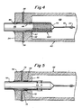
- FIG. 4 shows an alternate embodiment of the invention.
- the same reference characters are used to identify like parts of the arc tube previously referred to in FIG. 3.
- an arc tube 40 having an end wall 42 and having associated therewith a sealing disk 54. Both the sealing disk 54 and the arc tube end wall 42 have centrally disposed apertures 44 and 55 for receiving niobium tube 46.
- Niobium tube 46 in turn supports tungsten electrode wire 50 and associated turns 52.
- FIG. 4 illustrates the use of a helical coil 60A, preferably of tungsten wire in the range of approximately 3.0 to 5.0 mils wire diameter.
- the left-most end of helical coil 60A is disposed in aperture 44 such that a gasket is formed to prevent the glass sealing frit, such as at location 57, from extending into arc tube chamber 48.
- the remainder of helical coil 60A extends to cover substantially the length of niobium tube 46 within chamber 48 to shield the niobium inlead tube from attack by the arc constituents.
- the coil turns are closed, i.e., adjacent turns of the coil touch each other.
- This is advantageous in the embodiment of FIG. 4 where protection of the niobium tube from chemical reaction with fill constituents is desired.
- Further protection of the niobium tube can be achieved by coating the tube with tungsten, such as by sputtering or chemical vapor deposition directly on the tube. Such a coating may be used in the embodiment of FIG. 3 for providing protection to the niobium tube.
- FIG. 5 illustrates an alternate embodiment of the invention employing arc tube 64 having end wall 66 with a centrally disposed aperture having an annular channel therein.
- the aperture in end wall 66 is formed by two separate bores of respective diameters D1 and D2.
- Diameter D1 is larger than diameter D2 providing a shoulder in the bore at location 68.
- the helical tungsten coil 70 shown in cross section in the drawing, sits within the D1 bore against shoulder 68 and is wound about niobium tube 72, as illustrated in FIG. 5.
- the bore in end wall 66 at diameter D2 may be but slightly larger, say, approximately .001 inches or less, than the outer diameter of the niobium tube so that there is only a slight clearance space between the niobium tube and the end wall.
- Tungsten coil 70 provides a gasket for blocking sealing glass 74 and preventing sealing glass 74 form flowing into the arc tube chamber.
- the embodiment of FIG. 5 includes alumina button 76. Sealing frit 74 extends into the channel defined by diameter D1 and extends to, but is blocked by, the left-most turn of helical coil 70.
- FIGS. 6 and 7 Additional embodiments of the invention are described in FIGS. 6 and 7.
- the same reference characters are used to identify parts previously identified in FIG. 4.
- FIG. 6 there is shown arc tube 40 with end wall 42 having aperture 44 for receiving niobium tube 46.
- Sealing disk 54 has centrally disposed aperture 55.
- diameter D3 represents the inner diameter of aperture 44
- dimension D4 represents the inner diameter of aperture 55.
- Diameter D3 is smaller than diameter D4 so that a shoulder at 45 is formed.
- Helical coil 80 shown in cross section in the drawing, is urged at one end against shoulder 45 and extends at the other end to the outside surface of sealing disk 54.
- Coil 80 may be a closed coil as shown.
- Coil 80 contacting shoulder 45, forms a gasket to prevent sealing frit 56 from extending into aperture 44 at end wall 42.
- Frit 56 seals between end wall 42 and sealing disk 54, and frit 57 seals between sealing disk 54 and niobium tube 46.
- FIG. 7 illustrates still a further embodiment of the invention also employing an arc tube 40, an end wall 42, an associated sealing disk 54, and glass sealing frit 56.
- Niobium tube 46 extends through apertures in both end wall 42 and sealing disk 54.
- Coil 82 shown in cross section in the drawing, extends the width of sealing disk 54 and further partially into the aperture in end wall 42.
- the aperture in end wall 42 is tapered at 43 so as to limit the inner position of the coil 82 within the aperture of end wall 42.
- Glass frit 56 provides a seal between end wall 42 and sealing disk 54.
- Glass frit 57 provides a seal between the sealing disk 54 and niobium tube 46.
- the aperture in sealing disk 54 may be of a diameter to leave sufficient clearance space between the aperture and coil 82 so that some of the glass sealing frit extends into the aperture in sealing disk 54.
- the dimensions may be chosen so that there is a continuous glass sealing frit between locations 56 and 57. Because of the taper on the aperture at 43 in the end wall 42, the glass sealing frit will not extend beyond the right-most turn of coil 82. Thus, no sealing frit extends into the arc tube chamber.
Landscapes
- Vessels And Coating Films For Discharge Lamps (AREA)
Applications Claiming Priority (2)
| Application Number | Priority Date | Filing Date | Title |
|---|---|---|---|
| US94144286A | 1986-12-15 | 1986-12-15 | |
| US941442 | 1986-12-15 |
Publications (2)
| Publication Number | Publication Date |
|---|---|
| EP0271877A2 true EP0271877A2 (fr) | 1988-06-22 |
| EP0271877A3 EP0271877A3 (fr) | 1990-07-04 |
Family
ID=25476467
Family Applications (1)
| Application Number | Title | Priority Date | Filing Date |
|---|---|---|---|
| EP87118580A Withdrawn EP0271877A3 (fr) | 1986-12-15 | 1987-12-15 | Traversée pour lampes à sodium et à halogénures métalliques |
Country Status (2)
| Country | Link |
|---|---|
| EP (1) | EP0271877A3 (fr) |
| JP (1) | JPS63160147A (fr) |
Cited By (6)
| Publication number | Priority date | Publication date | Assignee | Title |
|---|---|---|---|---|
| EP0472100A2 (fr) * | 1990-08-24 | 1992-02-26 | Patent-Treuhand-Gesellschaft für elektrische Glühlampen mbH | Lampe à décharge à haute pression |
| EP0573880A1 (fr) * | 1992-06-10 | 1993-12-15 | Patent-Treuhand-Gesellschaft für elektrische Glühlampen mbH | Lampe à décharge haute pression |
| EP0639853A1 (fr) * | 1993-08-16 | 1995-02-22 | Patent-Treuhand-Gesellschaft für elektrische Glühlampen mbH | Lampe à décharge à haute pression avec récipient à décharge en céramique |
| EP0926700A2 (fr) * | 1997-12-24 | 1999-06-30 | Ngk Insulators, Ltd. | Lampe à décharge haute pression |
| EP1006560A2 (fr) * | 1998-12-04 | 2000-06-07 | Toshiba Lighting & Technology Corporation | Traversée pour lampe à décharge à haute pression, circuit et système d'illumination avec une telle lampe |
| US6169366B1 (en) | 1997-12-24 | 2001-01-02 | Ngk Insulators, Ltd. | High pressure discharge lamp |
Families Citing this family (2)
| Publication number | Priority date | Publication date | Assignee | Title |
|---|---|---|---|---|
| US7615929B2 (en) * | 2005-06-30 | 2009-11-10 | General Electric Company | Ceramic lamps and methods of making same |
| CN101980353B (zh) * | 2010-10-14 | 2013-04-17 | 杨潮平 | 共烧封接高效陶瓷灯及其制备方法 |
Citations (2)
| Publication number | Priority date | Publication date | Assignee | Title |
|---|---|---|---|---|
| US4560903A (en) * | 1982-02-26 | 1985-12-24 | U.S. Philips Corporation | High pressure discharge lamp |
| SU1224856A1 (ru) * | 1984-09-26 | 1986-04-15 | Предприятие П/Я А-3609 | Электродный узел газоразр дной лампы |
-
1987
- 1987-12-14 JP JP31432087A patent/JPS63160147A/ja active Pending
- 1987-12-15 EP EP87118580A patent/EP0271877A3/fr not_active Withdrawn
Patent Citations (2)
| Publication number | Priority date | Publication date | Assignee | Title |
|---|---|---|---|---|
| US4560903A (en) * | 1982-02-26 | 1985-12-24 | U.S. Philips Corporation | High pressure discharge lamp |
| SU1224856A1 (ru) * | 1984-09-26 | 1986-04-15 | Предприятие П/Я А-3609 | Электродный узел газоразр дной лампы |
Cited By (12)
| Publication number | Priority date | Publication date | Assignee | Title |
|---|---|---|---|---|
| EP0472100A2 (fr) * | 1990-08-24 | 1992-02-26 | Patent-Treuhand-Gesellschaft für elektrische Glühlampen mbH | Lampe à décharge à haute pression |
| EP0472100A3 (en) * | 1990-08-24 | 1992-06-17 | Patent-Treuhand-Gesellschaft Fuer Elektrische Gluehlampen Mbh | High-pressure discharge lamp |
| EP0573880A1 (fr) * | 1992-06-10 | 1993-12-15 | Patent-Treuhand-Gesellschaft für elektrische Glühlampen mbH | Lampe à décharge haute pression |
| US5446341A (en) * | 1992-06-10 | 1995-08-29 | Patent-Treuhand-Gesellschaft F. Elektrische Gluehlampen Mbh | High-pressure electric discharge lamp with tight lead-through pin electrode connection and method of its manufacture |
| EP0639853A1 (fr) * | 1993-08-16 | 1995-02-22 | Patent-Treuhand-Gesellschaft für elektrische Glühlampen mbH | Lampe à décharge à haute pression avec récipient à décharge en céramique |
| EP0926700A2 (fr) * | 1997-12-24 | 1999-06-30 | Ngk Insulators, Ltd. | Lampe à décharge haute pression |
| EP0926700A3 (fr) * | 1997-12-24 | 1999-12-08 | Ngk Insulators, Ltd. | Lampe à décharge haute pression |
| US6169366B1 (en) | 1997-12-24 | 2001-01-02 | Ngk Insulators, Ltd. | High pressure discharge lamp |
| US6407504B1 (en) | 1997-12-24 | 2002-06-18 | Ngk Insulators, Ltd. | High pressure discharge lamp having composite electrode |
| CN100361267C (zh) * | 1997-12-24 | 2008-01-09 | 日本碍子株式会社 | 高压放电灯 |
| EP1006560A2 (fr) * | 1998-12-04 | 2000-06-07 | Toshiba Lighting & Technology Corporation | Traversée pour lampe à décharge à haute pression, circuit et système d'illumination avec une telle lampe |
| EP1006560A3 (fr) * | 1998-12-04 | 2001-12-12 | Toshiba Lighting & Technology Corporation | Traversée pour lampe à décharge à haute pression, circuit et système d'illumination avec une telle lampe |
Also Published As
| Publication number | Publication date |
|---|---|
| EP0271877A3 (fr) | 1990-07-04 |
| JPS63160147A (ja) | 1988-07-02 |
Similar Documents
| Publication | Publication Date | Title |
|---|---|---|
| US5424608A (en) | High-pressure discharge lamp with ceramic discharge vessel | |
| US6528945B2 (en) | Seal for ceramic metal halide discharge lamp | |
| US5075587A (en) | High-pressure metal vapor discharge lamp, and method of its manufacture | |
| US4475061A (en) | High-pressure discharge lamp current supply member and mounting seal construction | |
| US6853139B2 (en) | Cold-cathode discharge lamp and lamp device having reduced sputtering on internal lead-in wire | |
| JPS6213792B1 (fr) | ||
| US5001396A (en) | Arc tube and high pressure discharge lamp including same | |
| KR0130879B1 (ko) | 할고겐화 금속 아크 방전램프용 금속 실리 케이트 보호코팅 | |
| EP0271877A2 (fr) | Traversée pour lampes à sodium et à halogénures métalliques | |
| HU181520B (en) | Electric discharge lamp | |
| JPH0682545B2 (ja) | 高圧金属蒸気放電灯用発光管 | |
| US5550421A (en) | Discharge lamp with enhanced performance and improved containment | |
| EP0160445B1 (fr) | Dispositif de tube à decharge pour lampe à décharge à haute pression | |
| US4198586A (en) | High pressure metal vapor discharge lamp and seal structure therefor | |
| US6617790B2 (en) | Metal halide lamp with ceramic discharge vessel | |
| EP0204303A2 (fr) | Entrée de courant conique pour des températures élévées pour des lampes à décharge céramiques | |
| US6856079B1 (en) | Ceramic discharge lamp arc tube seal | |
| US8729800B2 (en) | High intensity discharge lamp with external antenna | |
| US5592048A (en) | Arc tube electrodeless high pressure sodium lamp | |
| JPS62283543A (ja) | 金属蒸気放電灯 | |
| JPH08273616A (ja) | 金属蒸気発光管の開口部の封止部構造 | |
| JPH0418204Y2 (fr) | ||
| EP0042151B1 (fr) | Lampe à vapeur de sodium à haute pression | |
| JPH1196968A (ja) | 高圧放電ランプおよび照明装置 | |
| JP2001283778A (ja) | 金属蒸気放電灯 |
Legal Events
| Date | Code | Title | Description |
|---|---|---|---|
| PUAI | Public reference made under article 153(3) epc to a published international application that has entered the european phase |
Free format text: ORIGINAL CODE: 0009012 |
|
| 17P | Request for examination filed |
Effective date: 19871215 |
|
| AK | Designated contracting states |
Kind code of ref document: A2 Designated state(s): BE DE FR GB NL |
|
| PUAL | Search report despatched |
Free format text: ORIGINAL CODE: 0009013 |
|
| AK | Designated contracting states |
Kind code of ref document: A3 Designated state(s): BE DE FR GB NL |
|
| STAA | Information on the status of an ep patent application or granted ep patent |
Free format text: STATUS: THE APPLICATION IS DEEMED TO BE WITHDRAWN |
|
| 18D | Application deemed to be withdrawn |
Effective date: 19900703 |