EP0271111B1 - Heizkesselanlage mit externer Abgasrückführung - Google Patents
Heizkesselanlage mit externer Abgasrückführung Download PDFInfo
- Publication number
- EP0271111B1 EP0271111B1 EP87118357A EP87118357A EP0271111B1 EP 0271111 B1 EP0271111 B1 EP 0271111B1 EP 87118357 A EP87118357 A EP 87118357A EP 87118357 A EP87118357 A EP 87118357A EP 0271111 B1 EP0271111 B1 EP 0271111B1
- Authority
- EP
- European Patent Office
- Prior art keywords
- air
- flue
- gas
- heating boiler
- pipe
- Prior art date
- Legal status (The legal status is an assumption and is not a legal conclusion. Google has not performed a legal analysis and makes no representation as to the accuracy of the status listed.)
- Expired - Lifetime
Links
- 238000004064 recycling Methods 0.000 title abstract 3
- 239000000567 combustion gas Substances 0.000 title abstract 2
- 238000011144 upstream manufacturing Methods 0.000 claims abstract description 7
- 239000007789 gas Substances 0.000 claims description 47
- 238000002485 combustion reaction Methods 0.000 claims description 19
- UGFAIRIUMAVXCW-UHFFFAOYSA-N Carbon monoxide Chemical compound [O+]#[C-] UGFAIRIUMAVXCW-UHFFFAOYSA-N 0.000 claims description 17
- 239000003546 flue gas Substances 0.000 claims description 17
- 238000010438 heat treatment Methods 0.000 claims description 13
- 239000000446 fuel Substances 0.000 claims description 5
- 230000001105 regulatory effect Effects 0.000 claims description 5
- XLYOFNOQVPJJNP-UHFFFAOYSA-N water Substances O XLYOFNOQVPJJNP-UHFFFAOYSA-N 0.000 claims description 2
- 229910001220 stainless steel Inorganic materials 0.000 claims 1
- 239000010935 stainless steel Substances 0.000 claims 1
- 238000009423 ventilation Methods 0.000 abstract description 5
- 239000002131 composite material Substances 0.000 description 4
- 150000001875 compounds Chemical class 0.000 description 4
- 238000001816 cooling Methods 0.000 description 2
- 230000000694 effects Effects 0.000 description 2
- 238000003780 insertion Methods 0.000 description 1
- 230000037431 insertion Effects 0.000 description 1
- 238000012423 maintenance Methods 0.000 description 1
- 238000012544 monitoring process Methods 0.000 description 1
Images

Classifications
-
- F—MECHANICAL ENGINEERING; LIGHTING; HEATING; WEAPONS; BLASTING
- F23—COMBUSTION APPARATUS; COMBUSTION PROCESSES
- F23C—METHODS OR APPARATUS FOR COMBUSTION USING FLUID FUEL OR SOLID FUEL SUSPENDED IN A CARRIER GAS OR AIR
- F23C9/00—Combustion apparatus characterised by arrangements for returning combustion products or flue gases to the combustion chamber
-
- F—MECHANICAL ENGINEERING; LIGHTING; HEATING; WEAPONS; BLASTING
- F23—COMBUSTION APPARATUS; COMBUSTION PROCESSES
- F23C—METHODS OR APPARATUS FOR COMBUSTION USING FLUID FUEL OR SOLID FUEL SUSPENDED IN A CARRIER GAS OR AIR
- F23C2202/00—Fluegas recirculation
- F23C2202/30—Premixing fluegas with combustion air
Definitions
- the invention relates to a boiler system according to the preamble of the main claim. It is known that exhaust gas recirculation or exhaust gas recirculation in fireplaces can achieve a reduction in NOx. From the patent specification FR-A-2 300 964, a generic boiler system is known in which the exhaust gases to be returned are taken from a vacuum-side vacuum area. One of the two exhaust pipes described there leads to the air intake box of the combustion air blower. The hot exhaust gases are collected and added to the fresh combustion air via ducts that cause cooling. They are passed through a sieve sleeve surrounding the fresh air flow. The exhaust gases are also cooled on parts of the boiler through which water flows.
- the French patent FR-A-1 587 944 describes another boiler system in which cool fresh air is mixed into the recirculated hot exhaust gases and, moreover, the exhaust gas is passed through a heat exchanger to preheat the heating oil before it is passed through an exhaust gas fan and the outside Exhaust gas recirculation line to the burner head of the forced draft burner is conveyed.
- This allows partial exhaust gas quantities to be traced back up to 25%, whereby the desired NOx reduction below 50 ppm is possible under certain operating conditions. It proves to be disadvantageous that an additional purchase and monitoring effort for the exhaust gas fan and constant additional operating costs for the electrical drive energy and the maintenance effort are required.
- the invention is based on the object of developing a generic boiler system without a complex device for recirculation and for mixing the exhaust gas with the fresh air and without an additional cooling device for the exhaust gas.
- an exhaust gas blower can be dispensed with or other suitable measures for conveying the partial exhaust gas quantity.
- a sufficient quantity of exhaust gas is returned by means of the suction effect of the combustion air blower in conjunction with the excess pressure on the exhaust side.
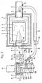
- Illustrations 1-5 show exemplary embodiments of the structure of the forced draft burner according to the invention with external exhaust gas recirculation - hereinafter also abbreviated to ARF - for the purpose of reducing the NO x to ⁇ 50 ppm.
- the pictures show a draw-in boiler 1 with a "hot" combustion chamber 2, exhaust gas deflection 3, exhaust pipe 4 and exhaust pipe 5.
- Each commercially available boiler of a different type, for example with 2 or 3 boiler trains, can also use the fan burner according to the invention to effectively reduce NO x operate.
- the burner flame 7 of the forced draft burner 9 burns, which is from the ventilation housing 10 with motor 11 and combustion air blower wheel 12, the burner housing 13 with burner head 14 and fuel supply 15, as well as with solenoid valve 16, gas regulating flap 17 and other gas safety fittings, furthermore the Burner flame tube 18 is formed in its main components.
- an air intake box 19 or alternatively an air intake port 20 is tightly attached to the inlet of the intake opening 21 of the valve housing 10.
- the air intake box 19 - or alternatively the air intake port 20 - has a combustion air cross section 22a open upstream of the atmosphere.
- the exemplary embodiments according to the invention shown in the pictures are boiler and fan burner designs known per se, which, as described below, are equipped with further inventive features.
- Figure 1 shows a forced draft burner according to the invention with a continuously modulating operating mode in a view from above, the boiler in the burner and flue connection plane being drawn in section A-B.
- the gas fan burner shows a partial section through the plane of the air intake opening 21 of the fan housing 10.
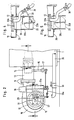
- Figure 2 shows a side view of this gas fan burner according to the invention from the outside with a partial view of the boiler.
- the air intake box 19 is firmly and tightly attached to the ventilation housing 10 in front of the intake opening 21; it has, at a right angle to the right of the suction opening 21, an end 22a which opens to the atmosphere and which, due to the movable air regulating flap 23a which can be adjusted with the servomotor 36, has a generally known manner in its air passage cross section, depending on the modulating burner setting can be changed.
- the exhaust gas recirculation line (ARF line) 32a is guided from the outside through the wall 25 of the air intake box 19 and further through the air throttle disk 24a through the air throttle disk 24a, which is adjustably arranged between the air control flap 23a and the impeller 12 in front of the air intake opening 21, that the open end protrudes into the plane of the impeller 12.
- ARF line exhaust gas recirculation line
- FIG. 1 shows the further design of the air throttle disk 24a, which is mounted twice on the ARF line 32a via a bracket 39 connected to it and is displaceably arranged via the threaded spindle 26 and the adjusting knob 27 in order to be able to preset the air intake opening 21.
- the air control flap 23a is used to actually adapt the instantaneous burner setting when the modulating fan burner is operated via an electronic burner control. The simultaneous regulation of the fuel supply 15 via the composite linkage need not be discussed here.
- the exhaust gas control flap 29 Connected to the air control flap 23a via the composite linkage 28a is the exhaust gas control flap 29, which is also installed according to the invention in the ARF line 35 upstream outside of the intake box 19 and which has the effect that the partial exhaust gas quantity is adjusted in accordance with the air flow rate associated with the modulating burner setting.
- the flue gas control flap 29 is likewise also opened further, in order to allow a larger part of the exhaust gas to flow in in this operating position and to ensure a sufficient proportion of exhaust gas in the combustion air for the desired NO x reduction.
- the exhaust gas control valve 29 causes it above it Compound linkage 28a with a low power and low air requirement, a restriction of the partial exhaust gas quantity in order to counteract the higher delivery pressure which occurs when the air control flap 23a is closed at the open end of the ARF line 32a in the area of the impeller 12.
- the ARF line 32a is fastened with the flange 33 to the wall 25 of the air intake box 19.
- the exhaust throttle valve 30 can be adjusted by hand and installed upstream of the exhaust gas control valve 29 in the external (outer) ARF line 35. It enables the partial exhaust gas quantity to be throttled independently of the position of the exhaust gas control flap 29.
- the ARF line 35 is routed outside the boiler 1 and opens into the exhaust pipe 5 behind the exhaust pipe 4 of the boiler 1, wherein it is fastened to the exhaust pipe with a flange 38 and opens out at an angle or alternatively in an arc shape with an open end 37 directed upstream .
- An additional exhaust gas build-up should increase the delivery pressure.
- the ARF line 35 is completely or partially designed in a fixed or flexible tube design.
- the ARF line with its open end 37 can be laid through the water-carrying part of the boiler in its rear exhaust gas path, which has to be done by the boiler being tuned by the manufacturer.
- This variant leads to even more cooled temperatures of the exhaust gas part quantity and enables a lower thermal load on the burner parts which it applies.
- Figure 3 shows a top view with a section at the center of the flue gas outlet through the boiler 1 and a partial section through the forced draft burner 9 in the plane of the air intake opening 21, another embodiment with a cylindrical air intake pipe 20, which bears close to the ventilation housing 10 in front of the intake opening 21 and the cylinder axis of which is arranged approximately in the middle of the motor and fan wheel axis and has a permanently adjustable air throttle disc 24b at its open end 22b.
- the air control flap 23b which is required for the modulating fan burner and is driven by the servomotor 36, is attached which in turn adjusts the exhaust gas control flap 29 mounted in the ARF line 35 in the same way via the composite linkage 28a - as already described.
- the air throttle disk 24b arranged at the open end 22b serves to preset an ARF line 32b which is sufficient for conveying the partial exhaust gas quantity even at the open position of the air control flap 23b at the ARF line 32b which is inserted laterally in the vicinity of the fan housing 10 into the air intake pipe and is bent at right angles to the fan wheel .
- the location for the ARF line insertion is selected in the area of the quadrant 34 which is not covered by the approximately 90 ° pivoting air control flap 23b.
- the air control flap 23b and the air throttle disk 24b can also be moved closer together with their center distances if the quadrants 34 not covered by the swivel angle are selected for the "overlap" for the adjustment range.
- the exhaust throttle valve 30 is installed upstream of the exhaust gas control valve 29.
- the ARF line 32b can be inserted into the air intake pipe 20 from both directions (horizontally from the front or rear, vertically from above or below) if the axial directions of the air regulating flap 23b and the air throttle disk 24b are simultaneously also pivoted.
- a particularly space-saving arrangement of the components within the air intake pipe 32b thus results, as already described, from the fact that the air throttle disk and the air control flap overlap in the uncovered quadrant of the swivel range and the ARF line is likewise introduced into such a quadrant 34.
- Figure 4 shows a further embodiment of the ARF line 32b with a modulating fan burner for the arrangement in the air intake pipe 20b.
- the fixed throttle disk 31 is used.
- FIG. 5 shows an embodiment for the single-stage fan burner version.
- the combustion air is preset in a shortened air tube 20c by means of the air throttle disk 24b.
- the ARF line only has the exhaust throttle valve 30.
Landscapes
- Engineering & Computer Science (AREA)
- Chemical & Material Sciences (AREA)
- Combustion & Propulsion (AREA)
- Mechanical Engineering (AREA)
- General Engineering & Computer Science (AREA)
- Combustion Of Fluid Fuel (AREA)
- Incineration Of Waste (AREA)
- Treating Waste Gases (AREA)
Description
- Die Erfindung geht aus von einer Heizkesselanlage nach der Gattung des Hauptanspruchs. Es ist bekannt, daß durch eine Abgasrückführung oder Abgasrezirkulation bei Feuerstätten eine NOx-Reduzierung erzielt werden kann. Durch die Patentschrift FR-A-2 300 964 ist eine gattungsgemäße Heizkesselanlage bekannt, bei der die rückzuführenden Abgase einem abgasseitigen Unterdruckbereich entnommen werden. Von den dort beschriebenen zwei Abgasrohren führt eines zum Luftansaugkasten des Verbrennungsluftgebläses. Die heißen Abgase werden gesammelt und über Kanäle, die eine Abkühlung bewirken, der Verbrennungsfrischluft beigegeben. Hierbei werden sie über eine den Frischluftstrom umgebende Siebmuffe geleitet. Die Abgase werden außerdem an wasserdurchströmten Kesselteilen abgekühlt.
- In der französischen Patentschrift FR-A- 1 587 944 ist eine andere Heizkesselanlage beschrieben, bei der den rückgeführten heißen Abgasen kühle Frischluft zugemischt wird und außerdem das Abgas zur Vorwärmung des Heizöles durch einen Wärmetauscher geleitet wird, bevor es über ein Abgasfördergebläse und die außen liegende Abgasrückführleitung zum Brennerkopf des Gebläsebrenners gefördert wird. Hierdurch sind Abgasteilmengen bis zu 25% rückführbar, wobei unter bestimmten Betriebsbedingungen die gewünschte NOx-Absenkung unter 50 ppm möglich ist. Als nachteilig erweist sich dabei, daß ein zusätzlicher Anschaffungs- und Überwachungsaufwand für das Abgasgebläse und ständige zusätzliche Betriebskosten für die elektrische Antriebsenergie und den Wartungsaufwand erforderlich sind.
- Der Erfindung liegt demgegenüber die Aufgabe zugrunde, eine gattungsgemäße Heizkesselanlage zu entwickeln ohne eine aufwendige Einrichtung zur Rückführung und zur Mischung des Abgases mit der Frischluft und ohne extra Kühleinrichtung für das Abgas.
- Diese Aufgabe wird erfindungsgemäß durch die im Kennzeichenteil des Hauptanspruchs genannten Merkmale gelöst. Durch diese erfindungsgemäße Ausführung, bei der das Abgas an einem abgasseitigen Überdruckbereich entnommen wird, kann auf ein Abgasgebläse verzichtet werden oder sonstige geeignete Maßnahmen zur Förderung der Abgasteilmenge. Dabei wird mittels der Saugwirkung des Verbrennungsluftgebläses in Verbindung mit dem abgasseitigen Überdruck eine Abgasteilmenge in ausreichender Menge zurückgeführt. Außer den eingesparten zusätzlichen Kosten für ein Absatzgebläse werden auch zusätzliche Betriebsgeräusche vermieden, die den Einsatz im Industrie-, Gewerbeund Haushaltssektor belasten könnten.
- In den Bildern 1-5 sind Ausführungsbeispiele über den erfindungsgemäßen Aufbau des Gebläsebrenners mit externer Abgasrückführung -nachfolgend auch abgekürzt ARF genannt- zum Zwecke der NOx-Reduzierung auf < 50 ppm dargestellt. Die Bilder zeigen einen Einzug-Kessel 1 mit "heißer" Brennkammer 2, Abgasumlenkung 3, Abgasstutzen 4 und Abgasrohr 5. Jeder handelsübliche Kessel anderer Bauart, bspw. mit 2 oder 3 Kesselzügen, kann mit dem erfindungsgemäßen Gebläsebrenner ebenfalls zur wirksamen NOx-Reduzierung betrieben werden. In der mit 6 bezeichneten Feuerraum brennt die Brennerflamme 7 des Gebläsebrenners 9, der vom Ventilationsgehäuse 10 mit Motor 11 und Verbrennungsluft-Gebläserad 12, dem Brennergehäuse 13 mit Brennerkopf 14 und Brennstoffzufuhr 15, sowie mit Magnetventil 16, Gasregelklappe 17 und anderen Gassicherheitsarmaturen, ferner dem Brennerflammrohr 18 in seinen Hauptbestandteilen gebildet wird. In an sich weiterhin bekannter Weise ist ein Luftansaugkasten 19 oder alternativ ein Luftansaugstutzen 20 am Eingang der Ansaugöffnung 21 des Ventilgehäuses 10 dicht befestigt. Der Luftansaugkasten 19 -oder alternativ der Luftansaugstutzen 20 - weist stromaufwärts einen gegenüber der Atmosphäre offenen Verbrennungsluftquerschnitt 22a auf. Insoweit handelt es sich bei den in den Bildern dargestellten erfindungsgemäßen Ausführungsbeispielen um an sich bekannte Kessel-und Gebläsebrenner-Ausführungen, die, wie nachfolgend beschrieben, mit weiteren erfinderischen Merkmalen ausgerüstet sind.
- Bild 1 zeigt einen erfindungsgemäßen Gebläsebrenner mit stufenlos modulierend arbeitender Betriebsweise in einer Ansicht von oben, wobei der Kessel in Brenner-und Abgasstutzenebene im Schnitt A-B gezeichnet ist. Der Gasgebläsebrenner zeigt dabei einen Teilschnitt durch die Ebene der Luftansaugöffnung 21 des Ventilatorgehäuses 10.
- Bild 2 zeigt eine Seitenansicht dieses erfindungsgemäßen Gasgebläsebrenner von außen mit Teilansicht vom Kessel. Wie aus Bild 1 hervorgeht, ist der Luftansaugkasten 19 vor der Ansaugöffnung 21 am Ventilationsgehäuse 10 fest und dicht angebaut; er weist in einem rechten Winkel rechts seitlich zur Ansaugöffnung 21 ein zur Atmosphäre hin offendes Ende 22a auf, das durch die bewegliche, mit Stellmotor 36 verstellbare Luftregelklappe 23a je nach modulierender Brennereinstellung in seinem Luftdurchlassquerschnitt in allgemein bekannter Weise verändert werden kann. Durch die zwischen Luftregelklappe 23a und Gebläserad 12 vor der Luftansaugöffnung 21 verstellbar angeordnete Luftdrosselscheibe 24a wird erfindungsgemäß die Abgasrückführungs-Leitung (ARF-Leitung) 32a von außen her durch die Wand 25 des Luftansaugkasten 19 und weiter durch die Luftdrosselscheibe 24a so weit nach innen geführt, daß das offene Ende in die Ebene des Gebläserades 12 hereinragt. An dieser Stelle besteht ein weitgehend gleichmäßiger, bei jeder Stellung der Luftregelklappe 23a und/oder der Luftdrosselscheibe 24a optimaler Unterdruck zur Förderung der extern in noch zu beschreibender Weise herangeführten Abgasteilmenge in der ARF-Leitung 35, wobei es im Bereich des Gebläserades 12 zu einer gleichmäßigen Verteilung und Vermischung mit der Verbrennungsluft kommt. Auf diese Weise kann auf eine mechanische Förderung mittels besonderer Abgasgebläse verzichtet werden, das ausschlaggebende Merkmal vorliegender Erfindung.
- Aus Bild 1 geht die weitere Ausbildung der Luftdrosselscheibe 24a hervor, die über einem mit ihr verbundenen Bügel 39 zweifach auf der ARF-Leitung 32a gelagert und über die Gewindespindel 26 und den Verstellknopf 27 verschieblich angeordnet ist, um die Luftansaugöffnung 21 voreinstellen zu können. Die Luftregelklappe 23a dient zur eigentlichen Anpassung der momentanen Brennereinstellung bei über eine elektronische Brennerregelung geregelter Betriebsweise des modulierenden Gebläsebrenners. Auf die gleichzeitige Regelung der Brennstoffzufuhr 15 über das Verbundgestänge braucht hier nicht eingegangen zu werden. Mit der Luftregelklappe 23a verbunden über das Verbundgestänge 28a ist die ebenfalls erfindungsgemäß in die ARF-Leitung 35 stromaufwärts außerhalb des Ansaugkasten 19 eingebaute Abgasregelklappe 29, die bewirkt, daß die Abgasteilmenge gemäß der modulierenden Brennereinstellung zugeordneten Luftdurchsatz angepaßt wird. Bei größerer Brenner- und damit Lufteinstellung wird die Abgasregelklappe 29 sinngemäß ebenfalls weiter geöffnet, um in dieser Betriebsstellung eine größere Abgasteilmenge einströmen zu lassen und einen ausreichenden Abgasanteil in der Verbrennungsluft zur angestrebten NOx-Absenkung zu gewährleisten.
- Andererseits bewirkt die Abgasregelklappe 29 über ihr Verbundgestänge 28a bei kleiner Leistung und geringem Luftbedarf eine Drosselung der Abgasteilmenge, um dem höheren Förderdruck entgegenzuwirken, der sich bei mehr geschlossener Luftregelklappe 23a am offenen Ende der ARF-Leitung 32a im Bereich des Gebläserades 12 einstellt.
- Die ARF-Leitung 32a ist mit dem Flansch 33 an der Wand 25 des Luftansaugkastens 19 befestigt.
- Die Abgasdrosselklappe 30 ist von Hand zu verstellen und stromaufwärts zur Abgasregelklappe 29 in die externe (äußere) ARF-Leitung 35 eingebaut. Sie ermöglicht eine Vordrosselung der Abgasteilmenge unabhängig zur Stellung der Abgasregelklappe 29.
- Die ARF-Leitung 35 ist außerhalb des Kessels 1 herumgeführt und mündet in das Abgasrohr 5 hinter dem Abgasstutzen 4 des Kessels 1 ein, wobei sie am Abgasrohr mit einem Flansch 38 befestigt ist und winkel-oder alternative dazu bogenförmig mit stromaufwärts gerichtetem offenen Ende 37 einmündet. Damit soll ein zusätzlicher Abgasstau den Förderdruck erhöhen. Die ARF-Leitung 35 wird ganz oder teilweise in fester oder flexibler Rohrausführung ausgeführt.
- Alternativ dazu kann die ARF-Leitung mit ihrem offenen Ende 37 durch den wasserführenden Teil des Kessels hindurch in dessen hinteren Abgasweg verlegt sein, was durch eine herstellerseitige Abstimmung des Kessels zu erfolgen hat. Diese Variante führt zu noch stärker abgekühlten Temperaturen der Abgasteilmenge und ermöglicht eine geringere thermische Belastung der von ihr beaufschlagten Brennerteile.
- Bild 3 zeigt in einer Ansicht von oben mit einem Schnitt in Höhe Abgasstutzenmitte durch den Kessel 1 und einem Teilschnitt durch den Gebläsebrenner 9 in der Ebene der Luftansaugöffnung 21 ein anderes Ausführungsbeispiel mit einem zylindrischen Luftansaugrohr 20, das vor der Ansaugöffnung 21 dicht am Ventilationsgehäuse 10 anliegt und dessen Zylinderachse etwa mittig zur Motor-und Gebläseradachse angeordnet ist und an seinem offenen Ende 22b eine fest einstellbare Lufdrosselscheibe 24b aufweist. In Richtung Luftansaugöffnung 21 -stromabwärts-ist die für den modulierenden Gebläsebrenner erforderliche, vom Stellmotor 36 angetriebene Luftregelklappe 23b angebracht, die die ihrerseits die in der ARF-Leitung 35 montierte Abgasregelklappe 29 über das Verbundgestänge 28a -wie bereits beschrieben-in gleicher Weise verstellt. Die am offenen Ende 22b angeordnete Luftdrosselscheibe 24b dient zur Voreinstellung eines auch bei geöffneter Stellung der Luftregelklappe 23b noch für die Förderung der Abgasteilmenge ausreichenden Förderdruckes an der seitlich in Nähe des Ventilatorgehäuses 10 in das Luftansaugrohr 20 eingeführten und rechtwinklig zum Gebläserad hin abgebogenen ARF-Leitung 32b. Der Ort für die ARF-Leitungseinführung wird im Bereich des von der etwa 90°-schwenkenden Luftregelklappe 23b nicht erfaßten Quadranten 34 gewählt. Die Luftregelklappe 23b und die Luftdrosselscheibe 24b können mit ihren Achsabständen ebenfalls näher aneinander gerückt sein, wenn die für den Verstellbereich die vom Schwenkwinkel nicht erfaßten Quadranten 34 zur "Überlappung" gewählt werden.
- In weiterer Ergänzung der externen ARF-Leitung 35 nach Bild 3 ist die Abgasdrosselklappe 30 stromaufwärts zur Abgasregelklappe 29 eingebaut.
- Die Einführung der ARF-Leitung 32b in das Luftansaugrohr 20 kann von beiden Richtungen her (horizontal von vorne oder hinten, vertikal von oben oder unten) erfolgen, wenn gleichzeitig die Achsrichtungen der Luftregelklappe 23b und der Luftdrosselscheibe 24b mitgeschwenkt verlegt werden. Eine besonders raumsparende Anordnung der Bauteile innerhalb des Luftansaugrohres 32b ergibt sich also wie bereits beschrieben dadurch, daß sich die Luftdrosselscheibe und die Luftregelklappe im nicht bestrichenen Quadranten des Schwenkbereichs überlappen und die ARF-Leitung ebenfalls in einem solchen Quadranten 34 eingeführt wird.
Bild 4 stellt ein weiteres Ausführungsbeispiel der ARF-Leitung 32b bei modulierendem Gebläsebrenner für die Anordnung im Luftansaugrohr 20b dar. Anstelle der Luftdrosselscheibe 24b wird die fest montierte Festdrosselscheibe 31 eingesetzt. - Bild 5 zeigt ein Ausführungsbeispiel für die einstufige Gebläsebrennerausführung.
Hier entfallen die Bauteile "Luftregelklappe" und Verbundgestänge" für eine stufenlose Regelung der Verbrennungsluft. Statt dessen wird in einem verkürzten Luftrohr 20c die Verbrennungsluft mittels der Luftdrosselscheibe 24b voreingestellt. In Ergänzung dazu weist die ARF-Leitung nur noch die Abgasdrosselklappe 30 auf. -
- 1
- Kessel
- 2
- Brennkammer
- 3
- Abgasumlenkung
- 4
- Abgasstutzen
- 5
- Abgasrohr
- 6
- Feuerraum
- 7
- Brennerflamme
- 8
- 9
- Gebläsebrenner
- 10
- ventilationsgehäuse
- 11
- Motor
- 12
- Gebläserad
- 13
- Brennergehäuse
- 14
- Brennerkopf
- 15
- Brennstoffzufuhr
- 16
- Magnetventil
- 17
- Gasregelklappe
- 18
- Brennerflammrohr
- 19
- Luftansaugkasten
- 20
- Luftansaugrohr
- 20b
- Luftansaugrohr
- 20c
- Luftansaugrohr
- 21
- Luftansaugöffnung
- 22a
- verbrennungsluftquerschnitt
- 22b
- verbrennungsluftquerschnitt
- 23a
- Luftregelklappe
- 23b
- Luftregelklappe
- 23c
- Luftregelklappe
- 24a
- Luftdrosselscheibe
- 24b
- Luftdrosselscheibe
- 25
- Wand von 19
- 26
- Gewindespindel (Kesselzug)
- 27
- Verstellknopf
- 28a
- Verbundgestänge
- 28b
- Verbundgestänge
- 28c
- Verbundgestänge
- 29
- Abgasregelklappe
- 30
- Abgasdrosselklappe
- 31
- fest mont. Drosselscheibe
- 32a
- Endstück der ARF-Leitung
- 32b
- Endstück der ARF-Leitung
- 32c
- Endstück der ARF-Leitung
- 33
- Flansch
- 34
- Quadrant
- 35
- ARF-Leitung
- 36
- Stellmotor
- 38
- Flansch
- 39
- Bügelverbindung
- 40
- Kondensattasse
- 50
- Mantel
- 51
- Krümmungsstel
- 52
- Siphonrohr
Claims (10)
- Heizkesselanlage,- mit einem gas- oder ölbefeuerten Heizkessel,- mit einem Gebläsebrenner für Gas oder Öl, der einen Antriebsmotor, ein Verbrennungsluftgebläse mit Gebläserad (Radialgebläse), ein Ventilationsgehäuse mit Luftansaugkasten oder Luftansaugrohr, einen Brennerkopf, ein Flammrohr und eine die maximale Luftmenge steuernde, einstellbare Luftdrosselscheibe aufweist,- mit einem Abgasrohr,- und mit einer externen (außerhalb des Heizkessels verlaufenden) Abgasrückführleitung, die in den Unterdruckbereich des Luftansaugkastens bzw. Luftansaugrohrs mündet,
dadurch gekennzeichnet,- daß die Abgasrückführleitung (32a,b,c, 35) im Abgasrohr (5) oder in einem dem Feuerraum (6) nachgeschalteten Kesselzug (4) ihren Eingang (37) aufweist,- daß die Abgasrückführleitung (32a,b,c, 35) durch die Außenwand (25) des Luftsansaugkastens (19) bzw. Luftansaugrohrs (20) in Richtung Motorachse mindestens bis zur Stirnseitenöffnung des Gebläserades (12) geführt ist,- so daß die Abgasluftdurchmischung erst im Verbrennungsluftgebläse (12) erfolgt. - Heizkesselanlage nach Anspruch 1, dadurch gekennzeichnet, daß der Gebläsebrenner (9) eine Brennstoff-Luft-Verbundregelung aufweist, mit einem Brennstoffsteuerorgan (Gasregelklappe) (17), einer Luftregelklappe (23a,b,c) und einem Verbundgestänge (28a,b,c) sowie einem Stellmotor (36) für eines dieser Steuerorgane (17, 23a,b,c).
- Heizkesselanlage nach Anspruch 1 oder 2, dadurch gekennzeichnet, daß auf dem im Ansaugkasten (19) angeordneten Abschnitt (32a) der Abgasrückführleitung (35) die Luftdrosselscheibe (24a) relativ zu einer Luftansaugöffnung (21) verschiebbar gelagert ist und daß deren Lage über eine von außerhalb des Ansaugkastens (19) zugängliche Vorrichtung (27), insbesondere Gewindespindel (26), änderbar ist.
- Heizkesselanlage nach einem der Ansprüche 1-3, dadurch gekennzeichnet, daß die Luftdrosselscheibe (24a,b) und/oder die Luftregelklappe (23a,b) stromauf des Gebläserades (12) mit quer zur Luftströmrichtung verlaufender Schwenkachse angeordnet sind und daß das Endstück (32a,b) der Abgasrückführleitung (35) senkrecht zur Schwenkachse und neben mindestens einem dieser Steuerorgane (23a,b, 24a,b) verläuft und zwar in dem von dessen Schwenkbereich nicht erfassten Quadranten (34).
- Heizkesselanlage nach einem der Ansprüche 1-4, dadurch gekennzeichnet, daß in der Abgasrückführleitung (35) vorzugsweise außerhalb des Luftansaugkastens (19) bzw. des Luftansaugrohrs (20) eone Abgasregelklappe (29) angeordnet ist, die über einen Stellmotor (36) in Abhängigkeit von Verbrennungskenngrößen verstellbar ist.
- Heizkesselanlage nach Anspruch 5, dadurch gekennzeichnet, daß die Abgasregelklappe (29) über ein Verbundgestänge (28a,b,c) mit der Luftregelklappe (23a,b,c) und/oder dem Brennstoffsteuerorgan (17) verbunden ist.
- Heizkesselanlage nach einem der Ansprüche 1-6, dadurch gekennzeichnet, daß die Abgasrückführleitung (35) von einem nachgeschalteten Kesselzug abzweigt und durch einen wasserführenden Mantel durchgeführt ist, wobei der Eingang (37) der Abgasrückführleitung (35) noch innerhalb des Kessels (1), aber außerhalb des Feuerraumes (6), angeordnet ist.
- Heizkesselanlage nach einem der Ansprüche 1-7, dadurch gekennzeichnet, daß der Eingang (37) der Abgasrückführleitung (35) dem Abgasstrom entgegengerichtet ist.
- Heizkesselanlage nach einem der Ansprüche 1-8, dadurch gekennzeichnet, daß die Abgasrückführleitung (35) zumindest abschnittsweise flexibel ausgebildet ist und vorzugsweise aus biegsamem Edelstahlwellrohr besteht.
- Heizkesselanlage nach einem der Ansprüche 1-9, dadurch gekennzeichnet, daß die Abgasrückführleitung (35) nach außen wärmeisoliert ist.
Priority Applications (1)
| Application Number | Priority Date | Filing Date | Title |
|---|---|---|---|
| AT87118357T ATE63996T1 (de) | 1986-12-11 | 1987-12-11 | Heizkesselanlage mit externer abgasrueckfuehrung. |
Applications Claiming Priority (2)
| Application Number | Priority Date | Filing Date | Title |
|---|---|---|---|
| DE3642357 | 1986-12-11 | ||
| DE3642357 | 1986-12-11 |
Publications (3)
| Publication Number | Publication Date |
|---|---|
| EP0271111A2 EP0271111A2 (de) | 1988-06-15 |
| EP0271111A3 EP0271111A3 (en) | 1988-11-30 |
| EP0271111B1 true EP0271111B1 (de) | 1991-05-29 |
Family
ID=6315982
Family Applications (1)
| Application Number | Title | Priority Date | Filing Date |
|---|---|---|---|
| EP87118357A Expired - Lifetime EP0271111B1 (de) | 1986-12-11 | 1987-12-11 | Heizkesselanlage mit externer Abgasrückführung |
Country Status (4)
| Country | Link |
|---|---|
| US (1) | US4926765A (de) |
| EP (1) | EP0271111B1 (de) |
| AT (1) | ATE63996T1 (de) |
| DE (1) | DE3770425D1 (de) |
Cited By (1)
| Publication number | Priority date | Publication date | Assignee | Title |
|---|---|---|---|---|
| CN108351099A (zh) * | 2015-10-19 | 2018-07-31 | 贝尔泰利联合公司 | 减少具有密封的强制通风燃烧室的燃气锅炉的有害气体排放物的方法和相应的锅炉 |
Families Citing this family (26)
| Publication number | Priority date | Publication date | Assignee | Title |
|---|---|---|---|---|
| US5193995A (en) * | 1987-12-21 | 1993-03-16 | Asea Brown Boveri Ltd. | Apparatus for premixing-type combustion of liquid fuel |
| CH680816A5 (de) * | 1989-04-27 | 1992-11-13 | Asea Brown Boveri | |
| CH680157A5 (de) * | 1989-12-01 | 1992-06-30 | Asea Brown Boveri | |
| JPH0628682B2 (ja) * | 1989-12-16 | 1994-04-20 | 大阪富士工業株式会社 | パルス燃焼式乾燥装置の熱回収システム |
| AT396821B (de) * | 1990-03-21 | 1993-12-27 | Vaillant Gmbh | Öl- oder gas-gebläsebrenner |
| US5259342A (en) * | 1991-09-11 | 1993-11-09 | Mark Iv Transportation Products Corporation | Method and apparatus for low NOX combustion of gaseous fuels |
| US5195883A (en) * | 1992-04-01 | 1993-03-23 | Aqua-Chem, Inc. | Flue gas recirculation system with fresh air purge for burners |
| MX9404582A (es) * | 1993-06-17 | 1995-01-31 | Pvi Ind Inc | Aparato calentador de agua con recirculacion pasiva de gases de lacombustion. |
| FR2711224B1 (fr) * | 1993-10-12 | 1995-12-08 | Guillot Ind Sa | Dispositif de chauffage à recyclage partiel des gaz de combustion. |
| US5551166A (en) * | 1994-03-07 | 1996-09-03 | Astec Industries, Inc. | Dryer drum coater having vented outer shell for VOC/NOx reduction |
| JPH09229349A (ja) * | 1996-02-23 | 1997-09-05 | Toyota Motor Corp | 熱流体発生炉 |
| US6126440A (en) * | 1996-05-09 | 2000-10-03 | Frazier-Simplex, Inc. | Synthetic air assembly for oxy-fuel fired furnaces |
| US6095792A (en) | 1998-08-21 | 2000-08-01 | Texaco Inc. | Flue gas recirculation system and method |
| EP1188930B2 (de) * | 2000-09-14 | 2007-06-13 | PUNKER GmbH & CO. | Gebläseanordnung, insbesondere Radialgebläseanordnung |
| US6609907B1 (en) * | 2001-02-13 | 2003-08-26 | Entropy Technology And Environmental Consultants, Lp | Apparatus and method to control emissions of nitrogen oxide |
| DE10110810A1 (de) * | 2001-03-06 | 2002-09-12 | Siemens Building Tech Ag | Anordnung eines Feuerungsautomaten für einen Gas- oder Ölbrenner |
| US6604474B2 (en) * | 2001-05-11 | 2003-08-12 | General Electric Company | Minimization of NOx emissions and carbon loss in solid fuel combustion |
| FR2837263B1 (fr) * | 2002-03-12 | 2004-09-24 | Air Liquide | Procede de mise en oeuvre d'une chaudiere de recuperation de chaleur |
| US7374735B2 (en) * | 2003-06-05 | 2008-05-20 | General Electric Company | Method for nitrogen oxide reduction in flue gas |
| US6776609B1 (en) * | 2003-06-26 | 2004-08-17 | Alzeta Corporation | Apparatus and method of operation for burners that use flue gas recirculation (FGR) |
| US7425127B2 (en) * | 2004-06-10 | 2008-09-16 | Georgia Tech Research Corporation | Stagnation point reverse flow combustor |
| KR100788267B1 (ko) * | 2005-08-01 | 2007-12-27 | 고일영 | 재생 폴리에틸렌 용융기의 배출가스 연소장치 |
| US8083517B2 (en) * | 2008-03-28 | 2011-12-27 | Fives North American Combustion, Inc. | Method of operating a furnace |
| CA2776547C (en) | 2009-10-14 | 2019-08-13 | Reklaim, Inc. | Pyrolysis process and products |
| DE102010051806A1 (de) * | 2010-11-18 | 2012-05-24 | Linde Aktiengesellschaft | Brenner mit einstellbarer Rauchgasrezirkulation |
| CN113167468B (zh) * | 2018-09-27 | 2023-10-24 | C.I.B.优尼瓦斯股份公司 | 用于废气再循环燃烧器的混合器 |
Family Cites Families (21)
| Publication number | Priority date | Publication date | Assignee | Title |
|---|---|---|---|---|
| US2224544A (en) * | 1940-12-10 | Temperature control foe tubular | ||
| US1634533A (en) * | 1924-01-05 | 1927-07-05 | Oil Devices Corp | Process of combustion |
| US1691541A (en) * | 1925-08-17 | 1928-11-13 | Iwan E Carlson | Oil burner |
| US1609150A (en) * | 1926-02-08 | 1926-11-30 | Oil Devices Corp | Control device for heating combustible mixtures |
| US1702936A (en) * | 1926-11-01 | 1929-02-19 | American Nokol Co | Liquid-fuel-burning apparatus |
| US1831529A (en) * | 1927-08-13 | 1931-11-10 | Petroleum Heat & Power Co | Liquid fuel burning means and method |
| US2813578A (en) * | 1954-02-08 | 1957-11-19 | Nat Airoil Burner Company Inc | Burners |
| US2918117A (en) * | 1956-10-04 | 1959-12-22 | Petro Chem Process Company Inc | Heavy fuel burner with combustion gas recirculating means |
| US3260227A (en) * | 1964-08-24 | 1966-07-12 | Foster Wheeler Corp | System for drying and burning wet coal |
| DE1501944B2 (de) * | 1965-02-06 | 1972-01-13 | Johann Vaillant Kg, 5630 Remscheid | Geblaese fuer oelvergasungsbrenner |
| LU52798A1 (de) * | 1967-01-12 | 1967-03-13 | ||
| NL6814200A (de) * | 1967-10-16 | 1969-04-18 | ||
| BE795261A (fr) * | 1972-02-10 | 1973-05-29 | Bailey Frank W | Bruleurs canon a retention de flamme bleue et systemes d'echangeur de chaleur |
| DE2365186A1 (de) * | 1973-12-29 | 1975-07-10 | Elco Oelbrennerwerk Ag | Verfahren und vorrichtung zum russfreien verbrennen von fluessigen brennstoffen |
| US3868211A (en) * | 1974-01-11 | 1975-02-25 | Aqua Chem Inc | Pollutant reduction with selective gas stack recirculation |
| SE395051B (sv) * | 1975-02-06 | 1977-07-25 | Hultgren Karl S H | Anordning vid oljebrennarhuvud |
| DE2605134C2 (de) * | 1975-02-12 | 1984-10-04 | Fascione, Pietro, Busto Arsizio, Varese | Vorrichtung zur Zuführung einer Mischung von Luft und rückgeführtem Rauchgas zu einem Brenner |
| US4312320A (en) * | 1980-06-16 | 1982-01-26 | Pa Incorporated | Incinerator apparatus and method |
| FR2565334A1 (fr) * | 1984-06-01 | 1985-12-06 | Deleage Sa | Chaudiere a condensation par voie seche |
| EP0193601A4 (de) * | 1984-09-12 | 1988-07-29 | Air Anti Pollution Ind Res Ltd | Verfahren und vorrichtung zur durchführung eines im wesentlichen isothermischen verbrennungsverfahrens in einem ofen. |
| US4725223A (en) * | 1986-09-22 | 1988-02-16 | Maxon Corporation | Incinerator burner assembly |
-
1987
- 1987-12-11 DE DE8787118357T patent/DE3770425D1/de not_active Expired - Fee Related
- 1987-12-11 EP EP87118357A patent/EP0271111B1/de not_active Expired - Lifetime
- 1987-12-11 AT AT87118357T patent/ATE63996T1/de active
-
1989
- 1989-04-04 US US07/334,738 patent/US4926765A/en not_active Expired - Fee Related
Cited By (2)
| Publication number | Priority date | Publication date | Assignee | Title |
|---|---|---|---|---|
| CN108351099A (zh) * | 2015-10-19 | 2018-07-31 | 贝尔泰利联合公司 | 减少具有密封的强制通风燃烧室的燃气锅炉的有害气体排放物的方法和相应的锅炉 |
| CN108351099B (zh) * | 2015-10-19 | 2020-10-23 | 贝尔泰利联合公司 | 减少具有密封的强制通风燃烧室的燃气锅炉的有害气体排放物的方法和相应的锅炉 |
Also Published As
| Publication number | Publication date |
|---|---|
| ATE63996T1 (de) | 1991-06-15 |
| DE3770425D1 (de) | 1991-07-04 |
| US4926765A (en) | 1990-05-22 |
| EP0271111A2 (de) | 1988-06-15 |
| EP0271111A3 (en) | 1988-11-30 |
Similar Documents
| Publication | Publication Date | Title |
|---|---|---|
| EP0271111B1 (de) | Heizkesselanlage mit externer Abgasrückführung | |
| CA2185078A1 (en) | Multi-direction after-air ports for staged combustion systems | |
| DE8915095U1 (de) | Heißwasserbereiter | |
| DE2819552A1 (de) | Heizungsanlage | |
| DE8717721U1 (de) | Heizkesselanlage mit externer Abgasrückführung | |
| DE19506803B4 (de) | Koch- und Heizofen | |
| EP1798470B1 (de) | Heizungsvorrichtung und Verfahren zu deren Betrieb | |
| DE1604299B2 (de) | Induktionsgeraet fuer hochdruckklimaanlagen | |
| DE1931155B2 (de) | Gerät zum Zuführen von Luft in einem Raum | |
| EP0415037B1 (de) | Gebläsebrenner für Heizkessel mit Abgasrückführung | |
| US4161941A (en) | Air inlet apparatus | |
| DE19539850C2 (de) | Klima- oder Heizungsanlage für Fahrzeuge | |
| DE19820067B4 (de) | Entschwadung für einen Backofen | |
| DE102011052267B4 (de) | Hallendeckenheizsystem mit brennwerttechnik | |
| DE3404589C2 (de) | ||
| AT398349B (de) | Leitungsanordnung für die be- und entlüftung eines raumes | |
| AT395211B (de) | Gasheizgeraet | |
| EP0141944B1 (de) | Zugregler für Schornsteinzug | |
| DE9319719U1 (de) | Brenner zur Dunkelstrahlheizung, der als kompakte Einheit mit Luft und Rezirkulationsventilator, Mischeinrichtung, Rezirkulationskammer, Luftkammer und Verbrennungsluftvorwärmung ausgestattet ist | |
| AT234958B (de) | Warmluftheizung | |
| DE69706731T2 (de) | Verbesserter Brenner für Wärmegenerator | |
| DE395836C (de) | Saugzug- und Unterwindanlage fuer Feuerungen mit gemeinsamer Regelung der beiden auf einer Welle sitzenden Ventilatoren | |
| DE722960C (de) | Regelvorrichtung fuer Kessel fuer feste Brennstoffe von Luftheizungsanlagen | |
| EP0859195B1 (de) | Abgasführung für ein Heizgerät | |
| LU85944A1 (de) | Direktbefeuerter lufterhitzer mit heizaggregat fuer eine warmluftheizung |
Legal Events
| Date | Code | Title | Description |
|---|---|---|---|
| PUAI | Public reference made under article 153(3) epc to a published international application that has entered the european phase |
Free format text: ORIGINAL CODE: 0009012 |
|
| AK | Designated contracting states |
Kind code of ref document: A2 Designated state(s): AT BE CH DE FR GB IT LI NL SE |
|
| PUAL | Search report despatched |
Free format text: ORIGINAL CODE: 0009013 |
|
| AK | Designated contracting states |
Kind code of ref document: A3 Designated state(s): AT BE CH DE FR GB IT LI NL SE |
|
| 17P | Request for examination filed |
Effective date: 19890527 |
|
| 17Q | First examination report despatched |
Effective date: 19900117 |
|
| GRAA | (expected) grant |
Free format text: ORIGINAL CODE: 0009210 |
|
| AK | Designated contracting states |
Kind code of ref document: B1 Designated state(s): AT BE CH DE FR GB IT LI NL SE |
|
| PG25 | Lapsed in a contracting state [announced via postgrant information from national office to epo] |
Ref country code: SE Effective date: 19910529 Ref country code: GB Effective date: 19910529 Ref country code: BE Effective date: 19910529 Ref country code: IT Free format text: LAPSE BECAUSE OF FAILURE TO SUBMIT A TRANSLATION OF THE DESCRIPTION OR TO PAY THE FEE WITHIN THE PRESCRIBED TIME-LIMIT;WARNING: LAPSES OF ITALIAN PATENTS WITH EFFECTIVE DATE BEFORE 2007 MAY HAVE OCCURRED AT ANY TIME BEFORE 2007. THE CORRECT EFFECTIVE DATE MAY BE DIFFERENT FROM THE ONE RECORDED. Effective date: 19910529 |
|
| REF | Corresponds to: |
Ref document number: 63996 Country of ref document: AT Date of ref document: 19910615 Kind code of ref document: T |
|
| REF | Corresponds to: |
Ref document number: 3770425 Country of ref document: DE Date of ref document: 19910704 |
|
| ET | Fr: translation filed | ||
| GBV | Gb: ep patent (uk) treated as always having been void in accordance with gb section 77(7)/1977 [no translation filed] | ||
| PG25 | Lapsed in a contracting state [announced via postgrant information from national office to epo] |
Ref country code: AT Effective date: 19911231 |
|
| PLBI | Opposition filed |
Free format text: ORIGINAL CODE: 0009260 |
|
| 26 | Opposition filed |
Opponent name: JOH. VAILLANT GMBH U. CO Effective date: 19920128 |
|
| NLR1 | Nl: opposition has been filed with the epo |
Opponent name: JOH. VAILLANT GMBH U. CO. |
|
| PLBM | Termination of opposition procedure: date of legal effect published |
Free format text: ORIGINAL CODE: 0009276 |
|
| STAA | Information on the status of an ep patent application or granted ep patent |
Free format text: STATUS: OPPOSITION PROCEDURE CLOSED |
|
| 27C | Opposition proceedings terminated |
Effective date: 19930708 |
|
| PGFP | Annual fee paid to national office [announced via postgrant information from national office to epo] |
Ref country code: FR Payment date: 19931217 Year of fee payment: 7 |
|
| PGFP | Annual fee paid to national office [announced via postgrant information from national office to epo] |
Ref country code: CH Payment date: 19940119 Year of fee payment: 7 |
|
| NLR2 | Nl: decision of opposition | ||
| PG25 | Lapsed in a contracting state [announced via postgrant information from national office to epo] |
Ref country code: LI Effective date: 19941231 Ref country code: CH Effective date: 19941231 |
|
| PG25 | Lapsed in a contracting state [announced via postgrant information from national office to epo] |
Ref country code: FR Effective date: 19950831 |
|
| REG | Reference to a national code |
Ref country code: CH Ref legal event code: PL |
|
| REG | Reference to a national code |
Ref country code: FR Ref legal event code: ST |
|
| PGFP | Annual fee paid to national office [announced via postgrant information from national office to epo] |
Ref country code: NL Payment date: 19991223 Year of fee payment: 13 |
|
| PGFP | Annual fee paid to national office [announced via postgrant information from national office to epo] |
Ref country code: DE Payment date: 20010226 Year of fee payment: 14 |
|
| PG25 | Lapsed in a contracting state [announced via postgrant information from national office to epo] |
Ref country code: NL Free format text: LAPSE BECAUSE OF NON-PAYMENT OF DUE FEES Effective date: 20010701 |
|
| NLV4 | Nl: lapsed or anulled due to non-payment of the annual fee |
Effective date: 20010701 |
|
| PG25 | Lapsed in a contracting state [announced via postgrant information from national office to epo] |
Ref country code: DE Free format text: LAPSE BECAUSE OF NON-PAYMENT OF DUE FEES Effective date: 20020702 |