EP0271075B1 - Connecting section for wall and ceiling panels - Google Patents
Connecting section for wall and ceiling panels Download PDFInfo
- Publication number
- EP0271075B1 EP0271075B1 EP87118226A EP87118226A EP0271075B1 EP 0271075 B1 EP0271075 B1 EP 0271075B1 EP 87118226 A EP87118226 A EP 87118226A EP 87118226 A EP87118226 A EP 87118226A EP 0271075 B1 EP0271075 B1 EP 0271075B1
- Authority
- EP
- European Patent Office
- Prior art keywords
- wall
- ceiling panels
- ceiling
- edge strip
- panels
- Prior art date
- Legal status (The legal status is an assumption and is not a legal conclusion. Google has not performed a legal analysis and makes no representation as to the accuracy of the status listed.)
- Expired - Lifetime
Links
Images

Classifications
-
- E—FIXED CONSTRUCTIONS
- E04—BUILDING
- E04B—GENERAL BUILDING CONSTRUCTIONS; WALLS, e.g. PARTITIONS; ROOFS; FLOORS; CEILINGS; INSULATION OR OTHER PROTECTION OF BUILDINGS
- E04B9/00—Ceilings; Construction of ceilings, e.g. false ceilings; Ceiling construction with regard to insulation
- E04B9/22—Connection of slabs, panels, sheets or the like to the supporting construction
- E04B9/24—Connection of slabs, panels, sheets or the like to the supporting construction with the slabs, panels, sheets or the like positioned on the upperside of, or held against the underside of the horizontal flanges of the supporting construction or accessory means connected thereto
- E04B9/241—Connection of slabs, panels, sheets or the like to the supporting construction with the slabs, panels, sheets or the like positioned on the upperside of, or held against the underside of the horizontal flanges of the supporting construction or accessory means connected thereto with the slabs, panels, sheets or the like positioned on the upperside of the horizontal flanges of the supporting construction
- E04B9/242—Connection of slabs, panels, sheets or the like to the supporting construction with the slabs, panels, sheets or the like positioned on the upperside of, or held against the underside of the horizontal flanges of the supporting construction or accessory means connected thereto with the slabs, panels, sheets or the like positioned on the upperside of the horizontal flanges of the supporting construction with separate retaining elements
-
- E—FIXED CONSTRUCTIONS
- E04—BUILDING
- E04B—GENERAL BUILDING CONSTRUCTIONS; WALLS, e.g. PARTITIONS; ROOFS; FLOORS; CEILINGS; INSULATION OR OTHER PROTECTION OF BUILDINGS
- E04B9/00—Ceilings; Construction of ceilings, e.g. false ceilings; Ceiling construction with regard to insulation
- E04B9/30—Ceilings; Construction of ceilings, e.g. false ceilings; Ceiling construction with regard to insulation characterised by edge details of the ceiling; e.g. securing to an adjacent wall
Definitions
- the invention relates to a connection profile for wall and ceiling panels, which has an angle profile with a support leg for the ends of the wall and ceiling panels and a fastening leg extending at right angles thereto and several retaining leaf springs pressing on the inside of the wall and ceiling panels, the free edge of the support leg has an inwardly folded edge strip by 180 ° and has the retaining leaf springs with one and the retaining leaf springs are attached with one end to the inside of the fastening leg.
- connection profiles serve to receive and support the ends of wall and ceiling panels.
- the individual wall and ceiling panels must be mountable from the front of the wall or the underside of the ceiling, since the other side - at least when installing and removing individual panels - is not accessible.
- a known connection profile of the type mentioned at the beginning (DE-GM 86 03 217) has an angular profile with a stepped cross section.
- the support leg and the fastening leg of the angle profile do not meet here, between them lies a step projecting towards the interior of the profile.
- this step forms an end face for the ends of the wall and ceiling panels, which ensures that the panels can no longer move in the longitudinal direction when installed.
- this step forms a cavity which is also accessible from the outside of the wall or the underside of the ceiling and into which the retaining leaf springs can be introduced. Longitudinal slots in the walls of this step are used to fasten and insert the retaining leaf springs so that they can press against the inside of the panels to hold them.
- connection profiles require considerable manufacturing effort in the manufacture of the connection profiles.
- the cavity visible and accessible from the outside or below, which is formed by the step, must then be clad. This requires a separate cladding panel, the manufacture and assembly of which leads to an increase in labor and costs.
- the object of the invention is therefore to provide a connection profile of the type mentioned, which enables simple and quick assembly and disassembly of the wall and ceiling panels and makes a separate attachment of the wall or ceiling panel unnecessary.
- the narrow edge strip forms the front contact edge for the wall and ceiling panels in order to prevent displacement in the longitudinal direction when installed. For dismantling, it is sufficient to lift one end of the panel over this edge strip by a small amount and to move it in the longitudinal direction towards the fastening leg, so that the other end of the panel is released from the connection profile arranged there.
- the retaining leaf springs only have to be pushed back a little without having to be removed. A panel is inserted in the reverse order.
- the support leg can therefore be designed with a smooth, continuous underside, so that an additional cladding plate is unnecessary.
- the support leg is angled immediately in front of the fastening leg and thus forms a smooth or the like up to the adjacent wall. continuous bottom surface.
- the front edge of the support leg is rounded off by folding over the edge strip. There is therefore no risk of damaging the visible surface of the wall and ceiling panels, especially if it is pushed over this edge during assembly or disassembly.
- the retaining leaf springs do not have to be loosened when installing and removing the panels, they can be attached, for example riveted, to the connection profile during the manufacture thereof. This significantly reduces the workload on the construction site.
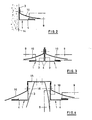
- connection profile with a panel accommodated thereon
- connection profile for a wall connection
- Fig. 3 shows the use of two connection profiles as a connecting rail of ceiling panels for larger spans and
- Fig. 4 shows the use of connecting profiles for connecting ceiling panels to a partition consisting of wall panels.
- connection profile 1 shown in detail in FIG. 1 and used in the application examples according to FIGS. 2-4 consists essentially of an angle profile 2 made of sheet metal, which has a mounting leg 3 and a support leg 4, which is directly from the mounting leg 3 by 190 ° is angled. At the free edge 5 of the support leg 4, an edge strip 6 is folded inwards by 180 °, so that it lies against the inside of the support leg 4.
- an edge strip 8 which is narrow in comparison to the width of the edge strip 6 is edged up by 90 °; it extends away from the support leg 4 and forms a contact edge for wall and ceiling panels 9, which are only indicated with dash-dotted lines in the figures.
- a plurality of retaining leaf springs 10 are arranged, which are fastened, for example riveted, to the fastening leg 3 with their one bent end 11. These attachment points are at a distance from the support leg 4, preferably in that half of the attachment leg 3 which faces away from the support leg 4.
- the retaining leaf springs 10 run at an acute angle, in the illustrated embodiment approximately 15-30 °, obliquely to the wall and ceiling panel 9.
- the free end 12 of each retaining leaf spring 10 extends beyond the edge strip 6 and presses in the assembled state onto the inside or 1.
- Top of the panel 9 and holds it in its position shown in FIG. 1, in which it cannot move in its longitudinal direction because of the edge strip 8 arranged on both ends of the panel.
- the fastening leg 3 of the connecting profile 1 is fastened to an existing wall 14, for example anchored.
- the connection profile 1 forms a wall connection of a false ceiling. Since the smooth underside of the support leg 4 extends to the wall 14, no cladding sheet is required.
- the space available above the panels 9 can be very small because the panels only have to be raised by a small amount predetermined by the width of the edge strip 8 during assembly and disassembly.
- connection profiles 1 are connected to one another at their fastening legs 3, for example riveted or screwed.
- the connected connecting profiles 1 here form a mounting rail for receiving panels 9 on both sides, which serve to form a false ceiling with a span that is greater than the length of the panel.
- connection profiles 1 each carrying ceiling panels 9 (left in Fig. 4 omitted), each with the upper edges via fastening legs 3 with a flat, inverted U-shaped head profile 15, which at one existing ceiling attached or can be suspended from this.
- the two fastening legs 3 form together with the head profile 15 a downwardly open ceiling rail for a partition arranged below it, of which only wall profiles 9 are indicated on one side in FIG. 4.
- These wall profiles 9 are pressed against the fastening legs 3 from the inside by retaining leaf springs 16.
Abstract
Description
Die Erfindung betrifft ein Anschlußprofil für Wand- und Deckenpaneele, das ein Winkelprofil mit einem Auflageschenkel für die Enden der Wand- und Deckenpaneele und einen sich im rechten Winkel dazu erstreckenden Befestigungsschenkel sowie mehrere auf die Innenseite der Wand- und Deckenpaneele drückende Halteblattfedern aufweist, wobei der freie Rand des Auflageschenkels einen nach innen um 180° umgefalteten Randstreifen aufweist und die Halteblattfedern mit ihrem einen aufweist und die Halteblattfedern mit ihrem einen Ende an der Innenseite des Befestigungsschenkels angebracht sind.The invention relates to a connection profile for wall and ceiling panels, which has an angle profile with a support leg for the ends of the wall and ceiling panels and a fastening leg extending at right angles thereto and several retaining leaf springs pressing on the inside of the wall and ceiling panels, the free edge of the support leg has an inwardly folded edge strip by 180 ° and has the retaining leaf springs with one and the retaining leaf springs are attached with one end to the inside of the fastening leg.
Derartige Anschlußprofile dienen dazu, die Enden von Wand-und Deckenpaneelen aufzunehmen und zu tragen. Bei der Montage und zu Reparaturzwecken müssen die einzelnen Wand-und Deckenpaneele von der Vorderseite der Wand bzw. der Unterseite der Decke her montierbar sein, da die andere Seite - zumindest beim Ein- und Ausbau einzelner Paneele - nicht zugänglich ist.Such connection profiles serve to receive and support the ends of wall and ceiling panels. During assembly and for repair purposes, the individual wall and ceiling panels must be mountable from the front of the wall or the underside of the ceiling, since the other side - at least when installing and removing individual panels - is not accessible.
Ein bekanntes Anschlußprofil der eingangs genannten Gattung (DE-GM 86 03 217) weist ein im Querschnitt treppenförmig gestaltetes Winkelprofil auf. Der Auflageschenkel und der Befestigungsschenkel des Winkelprofils treffen hierbei nicht aufeinander, zwischen ihnen liegt eine zum Profilinneren vorspringende Stufe. Diese Stufe bildet zum einen eine stirnseitige Anschlagfläche für die Enden der Wand- und Deckenpaneele, die dafür sorgt, daß die Paneele sich im eingebauten Zustand nicht mehr in Längsrichtung verschieben können.A known connection profile of the type mentioned at the beginning (DE-GM 86 03 217) has an angular profile with a stepped cross section. The support leg and the fastening leg of the angle profile do not meet here, between them lies a step projecting towards the interior of the profile. On the one hand, this step forms an end face for the ends of the wall and ceiling panels, which ensures that the panels can no longer move in the longitudinal direction when installed.
Zum anderen bildet diese Stufe einen auch von der Wandaußenseite bzw. der Deckenunterseite her zugänglichen Hohlraum, in den die Halteblattfedern eingebracht werden können. Längsschlitze in den Wänden dieser Stufe dienen zur Befestigung und zum Durchstecken der Halteblattfedern, damit diese auf die Innenseite der Paneele drücken können, um diese zu halten.On the other hand, this step forms a cavity which is also accessible from the outside of the wall or the underside of the ceiling and into which the retaining leaf springs can be introduced. Longitudinal slots in the walls of this step are used to fasten and insert the retaining leaf springs so that they can press against the inside of the panels to hold them.
Die Herstellung dieser Längsschlitze bedingt einen erheblichen Fertigungsaufwand bei der Herstellung der Anschlußprofile. Der von außen bzw. unten sichtbare und zugängliche Hohlraum, der durch die Stufe gebildet wird, muß anschließend verkleidet werden. Hierzu ist ein gesondertes Verkleidungsblech erforderlich, dessen Herstellung und Montage zu einer Erhöhung des Arbeits- und Kostenaufwands führt.The production of these longitudinal slots requires considerable manufacturing effort in the manufacture of the connection profiles. The cavity visible and accessible from the outside or below, which is formed by the step, must then be clad. This requires a separate cladding panel, the manufacture and assembly of which leads to an increase in labor and costs.
Zur Demontage einzelner Paneele müssen deren Enden bis über die Stufe des Winkelprofils angehoben werden, nachdem die jeweilige Halteblattfeder entfernt wurde. Für dieses Anheben muß ein ausreichender Platz hinter bzw. über den Paneelen zur Verfügung stehen.To dismantle individual panels, their ends must be raised to above the level of the angle profile after the respective retaining leaf spring has been removed. There must be sufficient space behind or above the panels for this lifting.
Bei einem bekannten Anschlußprofil für Wand- und Deckenpaneele der eingangs genannten Gattung (US-A-2 667 667) liegt der Randstreifen glatt auf der Oberseite des Auflageschenkels des Winkelprofils auf. Die Halteblattfedern ragen im nicht montierten Zustand und bei der Aufnahme von dünnen Wand- und Deckenpaneelen nicht über die Randstreifen hinaus. Deshalb müssen die Haltefedern einzeln angehoben werden, um die Wand- und Deckenpaneele zu montieren. Im montierten Zustand kann sich das Deckenpaneel horizontal verschieben, wenn es nicht durch gesonderte Maßnahmen festgehalten wird.In a known connection profile for wall and ceiling panels of the type mentioned at the beginning (US-A-2 667 667), the edge strip lies smoothly on the top of the support leg of the angle profile. The retaining leaf springs do not protrude beyond the edge strips when the wall and ceiling panels are not installed and when they are installed. For this reason, the retaining springs must be lifted individually in order to mount the wall and ceiling panels. When installed, the ceiling panel can move horizontally if it is not held in place by special measures.
Aufgabe der Erfindung ist es daher, ein Anschlußprofil der eingangs genannten Gattung zu schaffen, das eine einfache und rasche Montage und Demontage der Wand- und Deckenpaneele ermöglicht und eine gesonderte Befestigung des Wand- oder Deckenpaneels überflüssig macht.The object of the invention is therefore to provide a connection profile of the type mentioned, which enables simple and quick assembly and disassembly of the wall and ceiling panels and makes a separate attachment of the wall or ceiling panel unnecessary.
Diese Aufgabe wird erfindungsgemäß dadurch gelöst, daß an der inneren Kante des umgefalteten Randstreifens ein schmaler Kantenstreifen um mindestens 90° hochgekantet ist und daß sich die Halteblattfedern mit ihrem anderen Ende über den Randstreifen des Auflageschenkels hinauserstrecken.This object is achieved in that on the inner edge of the folded edge strip a narrow edge strip is edged by at least 90 ° and that the retaining leaf springs extend beyond the edge strip of the support leg with their other end.
Der schmale Kantenstreifen bildet hierbei die stirnseitige Anlagekante für die Wand- und Deckenpaneele, um eine Verschiebung in Längsrichtung in eingebautem Zustand zu verhindern. Zur Demontage genügt es, das eine Paneelende über diesen Kantenstreifen um einen geringen Betrag anzuheben und in Längsrichtung zum Befestigungsschenkel hin zu verschieben, so daß sich das andere Paneelende von dem dort angeordneten Anschlußprofil löst. Die Halteblattfedern müssen dabei nur etwas zurückgedrückt werden, ohne jedoch ausgebaut werden zu müssen. Das Einsetzen eines Paneels erfolgt im umgekehrten Ablauf.The narrow edge strip forms the front contact edge for the wall and ceiling panels in order to prevent displacement in the longitudinal direction when installed. For dismantling, it is sufficient to lift one end of the panel over this edge strip by a small amount and to move it in the longitudinal direction towards the fastening leg, so that the other end of the panel is released from the connection profile arranged there. The retaining leaf springs only have to be pushed back a little without having to be removed. A panel is inserted in the reverse order.
Bei der Montage und der Demontage von Paneelen brauchen die Halteblattfedern somit nicht zugänglich zu sein. Der Auflageschenkel kann daher mit glatter, durchgehender Unterseite ausgeführt sein, so daß ein zusätzliches Verkleidungsblech überflüssig ist.When mounting and dismantling panels, the retaining leaf springs do not need to be accessible. The support leg can therefore be designed with a smooth, continuous underside, so that an additional cladding plate is unnecessary.
Vorzugsweise ist der Auflageschenkel unmittelbar vor dem Befestigungsschenkel abgewinkelt und bildet somit eine glatte, bis zur benachbarten Wand o.dgl. durchlaufende Unterfläche.Preferably, the support leg is angled immediately in front of the fastening leg and thus forms a smooth or the like up to the adjacent wall. continuous bottom surface.
Die Vorderkante des Auflageschenkels ist durch das Umfalten des Randstreifens abgerundet. Deshalb besteht keine Gefahr einer Beschädigung der Sichtfläche der Wand-und Deckenpaneele, insbesondere wenn diese bei der Montage oder Demontage über diese Kante geschoben wird.The front edge of the support leg is rounded off by folding over the edge strip. There is therefore no risk of damaging the visible surface of the wall and ceiling panels, especially if it is pushed over this edge during assembly or disassembly.
Da die Halteblattfedern beim Ein- und Ausbau der Paneele nicht gelöst werden müssen, können sie bereits bei der Herstellung des Anschlußprofils an diesem angebracht, beispielsweise angenietet werden. Dadurch verringert sich der Arbeitsaufwand auf der Baustelle erheblich.Since the retaining leaf springs do not have to be loosened when installing and removing the panels, they can be attached, for example riveted, to the connection profile during the manufacture thereof. This significantly reduces the workload on the construction site.
Weitere vorteilhafte Ausgestaltungen des Erfindungsgedankens sind Gegenstand weiterer Unteransprüche.Further advantageous embodiments of the inventive concept are the subject of further dependent claims.
Die Erfindung wird nachfolgend an einem Ausführungsbeispiel und mehreren Anwendungsbeispielen näher erläutert, die in der Zeichnung dargestellt sind. Es zeigt:The invention is explained in more detail below using an exemplary embodiment and several application examples, which are shown in the drawing. It shows:
Fig. 1 im Schnitt und teilweise in räumlicher Darstellungsweise ein Anschlußprofil mit einem daran aufgenommenen Paneel,1 in section and partly in spatial representation a connection profile with a panel accommodated thereon,
Fig. 2 im senkrechten Schnitt die Verwendung des Anschlußprofils für einen Wandanschluß,2 in vertical section the use of the connection profile for a wall connection,
Fig. 3 die Verwendung zweier Anschlußprofile als Verbindungsschiene von Deckenpaneele für größere Spannweiten undFig. 3 shows the use of two connection profiles as a connecting rail of ceiling panels for larger spans and
Fig. 4 die Verwendung von Anschlußprofilen zum Anschluß von Deckenpaneelen an eine aus Wandpaneelen bestehende Trennwand.Fig. 4 shows the use of connecting profiles for connecting ceiling panels to a partition consisting of wall panels.
Das in Fig. 1 in Einzelheiten gezeigte und bei den Anwendungsbeispielen nach Fig. 2 - 4 verwendete Anschlußprofil 1 besteht im wesentlichen aus einem aus Blech gefertigten Winkelprofil 2, das einen Befestigungsschenkel 3 und einen Auflageschenkel 4 aufweist, der unmittelbar vom Befestigungsschenkel 3 um 190° abgewinkelt ist. Am freien Rand 5 des Auflageschenkels 4 ist ein Randstreifen 6 um 180° nach innen umgefaltet, so daß er an der Innenseite des Auflageschenkels 4 anliegt.The
An der inneren Kante 7 des Randstreifens 6 ist ein im Vergleich zur Breite des Randstreifens 6 schmaler Kantenstreifen 8 um 90° hochgekantet; er erstreckt sich vom Auflageschenkel 4 weg und bildet eine Anlagekante für Wand- und Deckenpaneele 9, die in den Figuren mit strichpunktierten Linien nur angedeutet sind.On the
Über die Länge des Winkelprofils 2 verteilt sind mehrere Halteblattfedern 10 angeordnet, die mit ihrem einen, abgekanteten Ende 11 am Befestigungsschenkel 3 befestigt, beispielsweise angenietet sind. Diese Befestigungsstellen liegen im Abstand zu dem Auflageschenkel 4, vorzugsweise in derjenigen Hälfte des Befestigungsschenkel 3, die dem Auflagegeschenkel 4 abgekehrt ist.Distributed over the length of the
Die Halteblattfedern 10 verlaufen in einem spitzen Winkel, beim dargestellten Ausführungsbeispiel etwa 15 - 30°, schräg zu dem Wand- und Deckenpaneel 9. Das freie Ende 12 jeder Halteblattfeder 10 erstreckt sich über den Randstreifen 6 hinaus und drückt im montierten Zustand auf die Innenseite bzw. Oberseite des Paneels 9 und hält dieses in seiner in Fig. 1 dargestellten Lage, in der es sich wegen des an beiden Paneelenden jeweils angeordneten Kantenstreifens 8 nicht in seiner Längsrichtung verschieben kann.The
Zur Demontage eines einzelnen Wand- und Deckenpaneels 9 genügt es, dessen eines in Fig. 1 dargestellte Ende in der durch Pfeile 13 angedeuteten Weise anzuheben und in Paneellängsrichtung zu verschieben, wobei die Halteblattfeder 10 leicht nach oben gebogen wird. Dadurch wird das andere, in Fig. 1 nicht gezeigte Ende des Wand-und Deckenpaneels 9 von dem dortigen Randstreifen 6 freigegeben und kann nach unten herausgenommen werden. Die Montage der Wand- und Deckenpaneele 9 erfolgt in umgekehrter Weise: zunächst wird ein Paneelende gegen die Kraft der Halteblattfeder 10 entsprechend den Pfeilen 13 nach oben gedrückt und in Längsrichtung verschoben, so daß das andere Paneelende auf den dortigen Randstreifen 6 aufgelegt werden kann. Sobald die Wand- und Deckenpaneele 9 in ihre mittlere Stellung verschoben werden, rasten die beiden Paneelenden zwischen den Kantenstreifen 8 der an beiden Enden befindlichen Anschlußprofile 1 ein.To dismantle a single wall and
Bei dem Ausführungsbeispiel nach Fig. 2 ist der Befestigungsschenkel 3 des Anschlußprofils 1 an einer vorhandenen Wand 14 befestigt, beispielsweise angedübelt. Das Anschlußprofil 1 bildet hierbei einen Wandanschluß einer Unterdecke. Da die glatte Unterseite des Auflageschenkels 4 bis zur Wand 14 reicht, ist kein Verkleidungsblech erforderlich. Der über den Paneelen 9 zur Verfügung stehende Platz kann sehr gering sein, weil die Paneele bei der Montage und Demontage nur um ein geringes, durch die Breite des Kantenstreifens 8 vorgegebenes Maß angehoben werden müssen.In the exemplary embodiment according to FIG. 2, the
Beim Beispiel nach Fig. 3 sind zwei Anschlußprofile 1 an ihren Befestigungsschenkeln 3 miteinander verbunden, beispielsweise vernietet oder verschraubt. Die verbundenen Anschlußprofile 1 bilden hierbei eine Tragschiene zur beiderseitigen Aufnahme von Paneelen 9, die zur Bildung einer Unterdecke mit einer Spannweite dienen, die größer als die Paneellänge ist.In the example according to FIG. 3, two
Bei dem in Fig. 4 gezeigten Beispiel sind zwei Anschlußprofile 1, die jeweils Deckenpaneele 9 tragen (links in Fig. 4 weggelassen), jeweils mit den oberen Rändern über Befestigungsschenkel 3 mit einem flachen, umgekehrt U-förmigen Kopfprofil 15 verbunden, das an einer vorhandenen Decke befestigt bzw. von dieser abgehängt sein kann. Die beiden Befestigungsschenkel 3 bilden zusammen mit dem Kopfprofil 15 eine nach unten geöffnete Deckenschiene für eine darunter angeordnete Trennwand, von der in Fig. 4 nur Wandprofile 9 auf einer Seite angedeutet sind. Diese Wandprofile 9 werden durch Halteblattfedern 16 von innen gegen die Befestigungsschenkel 3 gedrückt.In the example shown in Fig. 4, two
Claims (3)
- connecting section for wall and ceiling panels which has an angle profile (2) with a supporting flange (4) for the ends of the wall and ceiling panels (9) and an attachment flange (3) extending at a right-angle to this, and also several retaining sheet springs (10) pressing onto the inner side of the wall and ceiling panels (9), the free edge (5) of the supporting flange (4) having an edge strip (6) folded round inwards at 180° and the retaining sheet springs (10) being fitted with their one end (11) at the inner side of the attachment flange (3), characterised in that on the inner edge (7) of the folded-round edge strip (6) a narrow edge strip (8) is upended at at least 90° and that the retaining sheet springs (10) extend outwards with their other end (12) over the edge strip (6) of the supporting flange (4).
- Connecting section according to Claim 1, characterised in that the retaining sheet springs (10) are riveted on the attachment flange (3).
- Connecting section according to Claim 1, characterised in that the retaining sheet springs (10) run at an acute angle obliquely to the wall and ceiling sections (9).
Priority Applications (1)
| Application Number | Priority Date | Filing Date | Title |
|---|---|---|---|
| AT87118226T ATE62042T1 (en) | 1986-12-11 | 1987-12-09 | CONNECTION PROFILE FOR WALL AND CEILING PANELS. |
Applications Claiming Priority (2)
| Application Number | Priority Date | Filing Date | Title |
|---|---|---|---|
| DE3642337 | 1986-12-11 | ||
| DE19863642337 DE3642337A1 (en) | 1986-12-11 | 1986-12-11 | CONNECTION PROFILE FOR WALL AND CEILING PANELS |
Publications (2)
| Publication Number | Publication Date |
|---|---|
| EP0271075A1 EP0271075A1 (en) | 1988-06-15 |
| EP0271075B1 true EP0271075B1 (en) | 1991-03-27 |
Family
ID=6315968
Family Applications (1)
| Application Number | Title | Priority Date | Filing Date |
|---|---|---|---|
| EP87118226A Expired - Lifetime EP0271075B1 (en) | 1986-12-11 | 1987-12-09 | Connecting section for wall and ceiling panels |
Country Status (5)
| Country | Link |
|---|---|
| EP (1) | EP0271075B1 (en) |
| AT (1) | ATE62042T1 (en) |
| DE (2) | DE3642337A1 (en) |
| ES (1) | ES2022281B3 (en) |
| GR (1) | GR3002203T3 (en) |
Families Citing this family (4)
| Publication number | Priority date | Publication date | Assignee | Title |
|---|---|---|---|---|
| DE3923621A1 (en) * | 1989-07-17 | 1991-01-31 | Juergen Schmitt | PROFILE FOR SUPPORTING CEILING PANELS |
| DE8910940U1 (en) * | 1989-09-13 | 1989-11-23 | Hunter Douglas Industries B.V., Rotterdam, Nl | |
| DE19962820A1 (en) * | 1999-12-23 | 2001-06-28 | Kaefer Isoliertechnik | Connecting element for connecting expansion panels for interior construction and connection arrangement for expansion panels for interior construction |
| CN111794526B (en) * | 2020-07-24 | 2021-12-07 | 浙江中装建筑装饰有限公司 | Ceiling pinch plate installation method |
Family Cites Families (6)
| Publication number | Priority date | Publication date | Assignee | Title |
|---|---|---|---|---|
| GB578800A (en) * | 1943-06-24 | 1946-07-12 | Harold Norman Cartwright | Securing wall and ceiling boards to building frameworks |
| US2667667A (en) * | 1948-11-05 | 1954-02-02 | Level Line Ceilings Inc | Acoustic ceiling construction |
| FR1514146A (en) * | 1966-10-18 | 1968-02-23 | Aluminium Francais | Method allowing, in an air conditioning ceiling, to carry out the attachment of the ceiling panels to the support profiles and device implementing this method |
| FR2264935A1 (en) * | 1974-03-22 | 1975-10-17 | Conwed Corp | Suspended ceiling panel holding clamp - incorporating curved metal strip in two sections elastically expansible against each other |
| DE8535734U1 (en) * | 1985-12-19 | 1986-02-20 | Richter-System GmbH + Co KG, 6103 Griesheim | Ceiling cassette clip |
| DE8603217U1 (en) * | 1986-02-07 | 1986-04-24 | Richter-System GmbH & Co KG, 6103 Griesheim | Support kit for ceiling cladding panels |
-
1986
- 1986-12-11 DE DE19863642337 patent/DE3642337A1/en not_active Ceased
-
1987
- 1987-12-09 ES ES87118226T patent/ES2022281B3/en not_active Expired - Lifetime
- 1987-12-09 AT AT87118226T patent/ATE62042T1/en not_active IP Right Cessation
- 1987-12-09 DE DE8787118226T patent/DE3768925D1/en not_active Expired - Lifetime
- 1987-12-09 EP EP87118226A patent/EP0271075B1/en not_active Expired - Lifetime
-
1991
- 1991-06-27 GR GR91400879T patent/GR3002203T3/en unknown
Also Published As
| Publication number | Publication date |
|---|---|
| GR3002203T3 (en) | 1992-12-30 |
| ES2022281B3 (en) | 1991-12-01 |
| ATE62042T1 (en) | 1991-04-15 |
| DE3642337A1 (en) | 1988-07-14 |
| EP0271075A1 (en) | 1988-06-15 |
| DE3768925D1 (en) | 1991-05-02 |
Similar Documents
| Publication | Publication Date | Title |
|---|---|---|
| AT402594B (en) | DRAWER KIT DRAWER KIT | |
| DE3139829A1 (en) | POSTS FOR A REMOVABLE PARTITION | |
| DE3121657A1 (en) | WALL OR CEILING COVERING COMPOSED FROM PANELS | |
| CH636394A5 (en) | PANEL DESIGN. | |
| DE69923396T2 (en) | Signboard | |
| DE2652481A1 (en) | Intermediate ceiling panel carrier frame suspension element - has formed pleat inside length of anchor hooks engaging rail edges | |
| EP0271075B1 (en) | Connecting section for wall and ceiling panels | |
| DE19617269A1 (en) | Multi-part facade clip | |
| EP0458254B1 (en) | Fixing device for fixing a grip to a cooking vessel | |
| EP1205128B1 (en) | Shelf | |
| DE4335000A1 (en) | U-shaped connecting element for connecting metal C-profile rails | |
| EP0217268A2 (en) | Rectangular ceiling element for a sub-ceiling | |
| DE2950745A1 (en) | CLAMP FOR AN ACCESSIBLE REMOVABLE SUPPORTING SYSTEM OF A WALL PANELING CONSISTING OF PANELS | |
| CH650824A5 (en) | Jointed strip grid ceiling | |
| EP0956405B1 (en) | Set with an universal suspension element and a c-profile rail | |
| EP0465904B1 (en) | Ceiling cladding | |
| DE2334860C3 (en) | Partition wall used to form shelves | |
| EP0430271B1 (en) | Gridsystem for suspension ceiling | |
| EP1171674A1 (en) | Construction element assembly for forming a grid-shaped bearing structure | |
| EP0223802B1 (en) | Cross-connection for c profile bars of false ceilings | |
| EP0596193A1 (en) | Connecting element for joining metal C-sections | |
| DE2752963A1 (en) | WALL OR CEILING CONSTRUCTION | |
| EP0268221B1 (en) | Wall or ceiling panel | |
| DE2109596C3 (en) | Support frame for a false ceiling or the like | |
| DE10250498A1 (en) | Cover for roofs or facades has metal shingles hung on mounting rails with bent over upper sections engaging in hooks on rails so that locking elements on hooks enter mating locking elements on shingles |
Legal Events
| Date | Code | Title | Description |
|---|---|---|---|
| PUAI | Public reference made under article 153(3) epc to a published international application that has entered the european phase |
Free format text: ORIGINAL CODE: 0009012 |
|
| AK | Designated contracting states |
Kind code of ref document: A1 Designated state(s): AT BE CH DE ES FR GB GR IT LI LU NL SE |
|
| RBV | Designated contracting states (corrected) |
Designated state(s): AT BE CH DE ES FR GR LI NL |
|
| 17P | Request for examination filed |
Effective date: 19880926 |
|
| 17Q | First examination report despatched |
Effective date: 19891212 |
|
| GRAA | (expected) grant |
Free format text: ORIGINAL CODE: 0009210 |
|
| AK | Designated contracting states |
Kind code of ref document: B1 Designated state(s): AT BE CH DE ES FR GR LI NL |
|
| REF | Corresponds to: |
Ref document number: 62042 Country of ref document: AT Date of ref document: 19910415 Kind code of ref document: T |
|
| REF | Corresponds to: |
Ref document number: 3768925 Country of ref document: DE Date of ref document: 19910502 |
|
| ET | Fr: translation filed | ||
| PLBE | No opposition filed within time limit |
Free format text: ORIGINAL CODE: 0009261 |
|
| STAA | Information on the status of an ep patent application or granted ep patent |
Free format text: STATUS: NO OPPOSITION FILED WITHIN TIME LIMIT |
|
| 26N | No opposition filed | ||
| REG | Reference to a national code |
Ref country code: GR Ref legal event code: FG4A Free format text: 3002203 |
|
| PGFP | Annual fee paid to national office [announced via postgrant information from national office to epo] |
Ref country code: CH Payment date: 19921210 Year of fee payment: 6 |
|
| PGFP | Annual fee paid to national office [announced via postgrant information from national office to epo] |
Ref country code: GR Payment date: 19921216 Year of fee payment: 6 Ref country code: BE Payment date: 19921216 Year of fee payment: 6 |
|
| PGFP | Annual fee paid to national office [announced via postgrant information from national office to epo] |
Ref country code: FR Payment date: 19921222 Year of fee payment: 6 |
|
| PGFP | Annual fee paid to national office [announced via postgrant information from national office to epo] |
Ref country code: ES Payment date: 19921223 Year of fee payment: 6 |
|
| PGFP | Annual fee paid to national office [announced via postgrant information from national office to epo] |
Ref country code: NL Payment date: 19921231 Year of fee payment: 6 |
|
| PGFP | Annual fee paid to national office [announced via postgrant information from national office to epo] |
Ref country code: AT Payment date: 19930122 Year of fee payment: 6 |
|
| PG25 | Lapsed in a contracting state [announced via postgrant information from national office to epo] |
Ref country code: AT Effective date: 19931209 |
|
| PG25 | Lapsed in a contracting state [announced via postgrant information from national office to epo] |
Ref country code: LI Effective date: 19931231 Ref country code: CH Effective date: 19931231 Ref country code: BE Effective date: 19931231 |
|
| BERE | Be: lapsed |
Owner name: KAEFER ISOLIERTECHNI G.M.B.H. & CO. K.G. Effective date: 19931231 Owner name: RICHTER-SYSTEM G.M.B.H. & CO. K.G. Effective date: 19931231 |
|
| PG25 | Lapsed in a contracting state [announced via postgrant information from national office to epo] |
Ref country code: GR Free format text: THE PATENT HAS BEEN ANNULLED BY A DECISION OF A NATIONAL AUTHORITY Effective date: 19940630 |
|
| PG25 | Lapsed in a contracting state [announced via postgrant information from national office to epo] |
Ref country code: NL Effective date: 19940701 |
|
| NLV4 | Nl: lapsed or anulled due to non-payment of the annual fee | ||
| PG25 | Lapsed in a contracting state [announced via postgrant information from national office to epo] |
Ref country code: FR Effective date: 19940831 |
|
| REG | Reference to a national code |
Ref country code: CH Ref legal event code: PL |
|
| REG | Reference to a national code |
Ref country code: FR Ref legal event code: ST |
|
| PGFP | Annual fee paid to national office [announced via postgrant information from national office to epo] |
Ref country code: DE Payment date: 19941110 Year of fee payment: 8 |
|
| PG25 | Lapsed in a contracting state [announced via postgrant information from national office to epo] |
Ref country code: ES Free format text: LAPSE BECAUSE OF NON-PAYMENT OF DUE FEES Effective date: 19941210 |
|
| REG | Reference to a national code |
Ref country code: GR Ref legal event code: MM2A Free format text: 3002203 |
|
| PG25 | Lapsed in a contracting state [announced via postgrant information from national office to epo] |
Ref country code: DE Effective date: 19960903 |
|
| REG | Reference to a national code |
Ref country code: ES Ref legal event code: FD2A Effective date: 19950112 |