EP0270579B1 - Decanter centrifuge - Google Patents
Decanter centrifuge Download PDFInfo
- Publication number
- EP0270579B1 EP0270579B1 EP87903276A EP87903276A EP0270579B1 EP 0270579 B1 EP0270579 B1 EP 0270579B1 EP 87903276 A EP87903276 A EP 87903276A EP 87903276 A EP87903276 A EP 87903276A EP 0270579 B1 EP0270579 B1 EP 0270579B1
- Authority
- EP
- European Patent Office
- Prior art keywords
- conveyor
- centrifuge
- bowl
- radial
- body portion
- Prior art date
- Legal status (The legal status is an assumption and is not a legal conclusion. Google has not performed a legal analysis and makes no representation as to the accuracy of the status listed.)
- Expired - Lifetime
Links
Images

Classifications
-
- B—PERFORMING OPERATIONS; TRANSPORTING
- B04—CENTRIFUGAL APPARATUS OR MACHINES FOR CARRYING-OUT PHYSICAL OR CHEMICAL PROCESSES
- B04B—CENTRIFUGES
- B04B1/00—Centrifuges with rotary bowls provided with solid jackets for separating predominantly liquid mixtures with or without solid particles
- B04B1/20—Centrifuges with rotary bowls provided with solid jackets for separating predominantly liquid mixtures with or without solid particles discharging solid particles from the bowl by a conveying screw coaxial with the bowl axis and rotating relatively to the bowl
- B04B2001/2066—Centrifuges with rotary bowls provided with solid jackets for separating predominantly liquid mixtures with or without solid particles discharging solid particles from the bowl by a conveying screw coaxial with the bowl axis and rotating relatively to the bowl with additional disc stacks
Definitions
- This invention relates to a decanter centrifuge charged with a slurry to be separated into a solid phase and one or more liquid phases, the lighter one of which has a density higher than a predetermined minimum value, the decanter centrifuge comprising an axially symmetrical bowl journalled therein and a conveyor screw with a central body portion.
- a decanter centrifuge of this type is known from DE 28 19 399 A1. Such a decanter centrifuge is employed for separating a slurry supplied to the interior of the bowl into a solids phase and one or more liquid phases. This is obtained by rotating the entire centrifuge at a high number of revolutions and rotating at the same time the conveyor at a low number of revolutions relative to the bowl.
- the separating effect of the centrifuge and its capacity or throughput depend, on one hand, on the magnitude of the field of gravitation generated by the centrifugal force in the separating space of the bowl i.e. on the number of revolutions and the inner diameter of the bowl and, on the other hand, on the length of the separating space.
- a decanter centrifuge according to the invention which differs from the prior art centrifuges in that the average density of the conveyor screw i.e. the ratio between its total weight and the volume it displaces, is smaller than said minimum value, means being provided for adjusting the liquid level in the separating space between the body portion of the conveyor screw and the bowl so that during operation the outer surface of said body portion is substantially covered by liquid and at least one end of the conveyor being in operation unsupported in the radial direction in relation to the bowl.
- the decanter centrifuge 1 illustrated in Fig. 1 constists by and large of a horizontal, axially symmetrical bowl 2 with a cylindrical section 3 and a conical section 4.
- the bowl 2 includes an elongated conveyor screw 5 with a central body portion 6 and surrounded by a continuous screw flight 7.
- the bowl is at its ends rotatably supported in bearings 8 and 9, respectively, and is driven via a gear 10 - for example an epicyclic gear - ensuring in a known manner that bowl 2 and conveyor 5 in operation rotate relative to each other.
- the suspension to be separated is supplied through an inlet 11 in the form of an inlet tube 12 and extending coaxially with the axis of rotation of the centrifuge through a central passage 13 provided in conveyor body 6.
- the tube 12 ends in a transverse, radial passage 14 discharging into the separating space 15 of the centrifuge.
- the liquid level in operation is illustrated in dotted lines 16 and solid lines 17. After separation in space 15 solids are discharged through apertures 18 while liquid is discharged through an annular outlet 19.
- Conveyor 5 is by and large constructed as hollow body with closed cavities 20 and 21 and is so dimensioned that the average density of the conveyor as a whole is smaller than the density of the lighter liquid phase of the actual suspension.
- the average density of the conveyor is defined as the ratio between the total weight of the conveyor and the volume it displaces.
- the conveyor is able to flow in said light liquid phase which in operation constitutes the innermost portion of the "liquid tube” generated by centrifugal forces and positioned along the internal surface of the bowl wall.
- the conveyor body By adjusting the liquid level in separating space 15 - i.e. the wall thickness of the liquid tube - so that the outer surface of body portion 6 is substantially covered, it is obtained that the conveyor body may be regarded as approximately fully submerged and therefore in possession of a certain positive buoyancy.
- the result is that the conveyor will constantly seek towards the surface which in operation will mean towards the axis of rotation.
- the conveyor is in other words self-centering. Said effect has in practice proven to be independent of the degree of overlapping between the outer diameter of the body portion and the inner diameter of the liquid tube, provided a certain overlapping exists.
- a radial support bearing 22 the radial external surface of which is adapted to cooperate periodically with the radial internal surface of a circular collar 23 on the conveyor body.
- a certain radial clearance between the outer diameter of the supporting bearing and the inner diameter of the collar. Consequently, the bearing and the collar will only cooperate when the radial oscillation of the conveyor from the axis of rotation at the large end exceeds said clearance. This will for instance be the case when the centrifuge does not rotate or rotates at such a low number of revolutions that the liquid tube cannot be maintained and thus has no supporting ability.
- the clearance is so dimensioned that the conveyor in no circumstances can contact the bowl wall.
- the conveyor is journalled in an ordinary way by means of a traditional radial bearing 24.
- Said bearing may possibly be a spheric bearing in order to allow the slight angular movements of the conveyor which is a consequence of its radial deflection at the large end.
- a second possibility of allowing said angular movement is to make use of a sort of a diaphragm coupling between the drive shaft of the conveyor at the small end and the conveyor body proper.
- the conveyor is, in a manner not shown, controlled in the axial direction.
- the conveyor of a given traditionally constructed centrifuge has a weight of about 400 kg, while the conveyor of a corresponding centrifuge according to the invention can be manufactured with a weight of only about 100 kg.
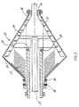
- Fig. 2 illustrates a second embodiment of a centrifuge according to the invention, namely a so-called disc decanter 25, i.e. a centrifuge including a pile of discs as well as a conveyor screw.
- a so-called disc decanter 25 i.e. a centrifuge including a pile of discs as well as a conveyor screw.
- Centrifuge 25 comprises a double-conical bowl 26 at the one end of which a pile of discs 27 is arranged which rotates with the bowl and at the other end of which a conveyor screw 28 is mounted which in operation rotates relative to bowl 26.
- the actual slurry is supplied through an inlet 29 and the separated phases are discharged from the bowl through apertures 30 and outlets 35 and 36, respectively, at the left-hand end of bowl 26 in Fig. 2.
- the liquid level in operation is designated by 31.
- the mode of operation of such a centrifuge is known and will therefore not be explained in detail here.
- conveyor 28 is constructed as a hollow body the radial journalling of which at the one end is effected by means of a periodically active, radial support bearing 32 and an annular collar 33.
- the other end of the conveyor is journalled by means of an ordinary radial bearing 34 and the conveyor is likewise controlled in the axial direction in relation to the drum.
- the radial support bearing is in both specified embodiments arranged at the "large end" of the conveyor, this being advantageous because the conveyor has there a comparatively greater buoyancy than at the small end.
- This relates to the fact that the body portion is conically tapered at the small end and thus accommodates less buoyancy promoting cavity volume per unit of length than is the case at the large end.
- the conveyor is not fully submerged at the small end. There is, however, nothing to prevent the support bearing from being positioned in other embodiments at the small end, and it is also possible to provide the conveyor with support bearings at both ends.
Landscapes
- Centrifugal Separators (AREA)
Applications Claiming Priority (2)
| Application Number | Priority Date | Filing Date | Title |
|---|---|---|---|
| DK2095/86 | 1986-05-06 | ||
| DK209586A DK154540C (da) | 1986-05-06 | 1986-05-06 | Dekantercentrifuge |
Publications (2)
| Publication Number | Publication Date |
|---|---|
| EP0270579A1 EP0270579A1 (en) | 1988-06-15 |
| EP0270579B1 true EP0270579B1 (en) | 1991-11-21 |
Family
ID=8110038
Family Applications (1)
| Application Number | Title | Priority Date | Filing Date |
|---|---|---|---|
| EP87903276A Expired - Lifetime EP0270579B1 (en) | 1986-05-06 | 1987-05-05 | Decanter centrifuge |
Country Status (6)
| Country | Link |
|---|---|
| US (1) | US4828541A (da) |
| EP (1) | EP0270579B1 (da) |
| JP (1) | JPH0813344B2 (da) |
| DE (1) | DE3774675D1 (da) |
| DK (1) | DK154540C (da) |
| WO (1) | WO1987006856A1 (da) |
Families Citing this family (14)
| Publication number | Priority date | Publication date | Assignee | Title |
|---|---|---|---|---|
| DK166996B1 (da) * | 1988-06-21 | 1993-08-16 | Alfa Laval Separation As | Dekantercentrifuge |
| DE4005755A1 (de) * | 1989-10-17 | 1991-04-18 | Kloeckner Humboldt Deutz Ag | Vollmantel-schneckenzentrifuge |
| DK166069C (da) * | 1989-12-29 | 1993-07-19 | Alfa Laval Separation As | Dekantercentrifuge |
| US5151079A (en) * | 1990-09-27 | 1992-09-29 | Conoco Specialty Products Inc. | Method and apparatus for reduction of particle disintegration |
| DE4115347C2 (de) * | 1991-05-10 | 1999-07-22 | Baker Hughes De Gmbh | Vollmantel-Schneckenzentrifuge zur Klassierung eines Feststoff-Flüssigkeitsgemisches |
| US5354255A (en) * | 1992-12-17 | 1994-10-11 | Alfa Laval Separation Inc. | Decanter centrifuge with conveyor capable of high speed and higher flow rates |
| ATE201833T1 (de) * | 1994-11-09 | 2001-06-15 | Incentra Aps | Dekantierzentrifuge |
| GB9611209D0 (en) * | 1996-05-29 | 1996-07-31 | Ecc Int Ltd | Decanter centrifuge |
| SE9701225D0 (sv) * | 1997-04-04 | 1997-04-04 | Alfa Laval Ab | Centrifugalseparator med slamtransportskruvar |
| US6030332A (en) * | 1998-04-14 | 2000-02-29 | Hensley; Gary L. | Centrifuge system with stacked discs attached to the housing |
| SE9802116D0 (sv) | 1998-06-15 | 1998-06-15 | Alfa Laval Ab | Dekantercentrifug |
| US6572524B1 (en) | 2000-07-14 | 2003-06-03 | Alfa Laval Inc. | Decanter centrifuge having a heavy phase solids baffle |
| DK200970028A (en) | 2009-06-12 | 2010-12-13 | Alfa Laval Corp Ab | A decanter centrifuge and a screw conveyor |
| CN103567080A (zh) * | 2013-10-21 | 2014-02-12 | 绿水分离设备有限公司 | 一种设有防护隔筋的卧式螺旋卸料沉降离心机 |
Citations (1)
| Publication number | Priority date | Publication date | Assignee | Title |
|---|---|---|---|---|
| DE2819399A1 (de) * | 1977-05-04 | 1978-11-16 | Joseph Fenwick Jackson | Vollmantel-abklaerzentrifuge |
Family Cites Families (13)
| Publication number | Priority date | Publication date | Assignee | Title |
|---|---|---|---|---|
| BE485392A (da) * | 1944-03-28 | |||
| US2679974A (en) * | 1947-01-15 | 1954-06-01 | Sharples Corp | Bearing construction for continuous centrifuge |
| US3148145A (en) * | 1963-03-25 | 1964-09-08 | Pennsalt Chemicals Corp | Solids discharge centrifuge |
| SE345210B (da) * | 1970-02-16 | 1972-05-23 | Asea Ab | |
| DE2212178A1 (de) * | 1972-03-14 | 1973-09-20 | Kloeckner Humboldt Deutz Ag | Spuelbare zentrifuge |
| US3854658A (en) * | 1973-05-07 | 1974-12-17 | Dorr Oliver Inc | Solid bowl conveyer type centrifuge |
| GB1397172A (en) * | 1973-05-19 | 1975-06-11 | V Ni In K I Khim Mash | Resilient rotor support for centrifugal machines |
| DE2525930A1 (de) * | 1975-06-11 | 1976-12-23 | Hoechst Ag | Verfahren zum abtrennen von feststoffen aus suspensionen |
| DE2819329A1 (de) * | 1977-05-04 | 1978-11-16 | Cornelius Scheybal | Rahmen |
| DE2813140A1 (de) * | 1978-03-25 | 1979-10-25 | Kloeckner Humboldt Deutz Ag | Vollmantel-schneckenzentrifuge |
| US4209128A (en) | 1979-04-06 | 1980-06-24 | Yara Engineering Corporation | Methods and apparatus for classifying fine particle solids |
| DE3518885A1 (de) * | 1985-05-25 | 1986-11-27 | Bayer Ag, 5090 Leverkusen | Vollmantelschneckenzentrifuge mit nachklaervorrichtung |
| JP2590195B2 (ja) * | 1988-04-06 | 1997-03-12 | 株式会社日立製作所 | 空燃比センサの信号取出し構造 |
-
1986
- 1986-05-06 DK DK209586A patent/DK154540C/da not_active IP Right Cessation
-
1987
- 1987-05-05 US US07/138,380 patent/US4828541A/en not_active Expired - Lifetime
- 1987-05-05 JP JP62503121A patent/JPH0813344B2/ja not_active Expired - Fee Related
- 1987-05-05 WO PCT/DK1987/000050 patent/WO1987006856A1/en not_active Ceased
- 1987-05-05 EP EP87903276A patent/EP0270579B1/en not_active Expired - Lifetime
- 1987-05-05 DE DE8787903276T patent/DE3774675D1/de not_active Expired - Lifetime
Patent Citations (1)
| Publication number | Priority date | Publication date | Assignee | Title |
|---|---|---|---|---|
| DE2819399A1 (de) * | 1977-05-04 | 1978-11-16 | Joseph Fenwick Jackson | Vollmantel-abklaerzentrifuge |
Also Published As
| Publication number | Publication date |
|---|---|
| WO1987006856A1 (en) | 1987-11-19 |
| DE3774675D1 (de) | 1992-01-02 |
| EP0270579A1 (en) | 1988-06-15 |
| DK154540C (da) | 1989-04-24 |
| DK209586A (da) | 1987-11-07 |
| DK154540B (da) | 1988-11-28 |
| DK209586D0 (da) | 1986-05-06 |
| JPS63503211A (ja) | 1988-11-24 |
| US4828541A (en) | 1989-05-09 |
| JPH0813344B2 (ja) | 1996-02-14 |
Similar Documents
| Publication | Publication Date | Title |
|---|---|---|
| EP0270579B1 (en) | Decanter centrifuge | |
| EP0221723B1 (en) | Centrifuge rotor inlet device | |
| US5147277A (en) | Power-efficient liquid-solid separating centrifuge | |
| US4245777A (en) | Centrifuge apparatus | |
| CA1167818A (en) | Solids-liquid slurry separating centrifuge | |
| US1664769A (en) | Method and apparatus for centrifugal thickening of mixtures and clarifying of liquids | |
| GB2138715A (en) | High capacity continuous solid bowl centrifuge | |
| US7153255B2 (en) | Screw centrifuge for the wet mechanical separation of solids | |
| SE507107C2 (sv) | Centrifugalseparator med maxlaststart | |
| US20220401965A1 (en) | Inlet region of a centrifuge screw, and solid bowl centrifuge | |
| US4265740A (en) | Centrifugal separator | |
| US5545119A (en) | Solid bowl worm centrifuge | |
| EP1304170B1 (en) | Centrifugal separator | |
| JP2997700B2 (ja) | デカンタ型遠心分離機 | |
| US5836530A (en) | Paper manufacture conical-type pulp refiners improvements | |
| GB2083381A (en) | Uniflow decanter centrifuge | |
| EP0506835B1 (en) | Decanter centrifuge | |
| CA1233445A (en) | Centrifugal separator | |
| EP1392445B1 (en) | Decanter centrifuge with a gear box mounted on the bowl | |
| EP0258012A2 (en) | A centrifugal solids-liquids separator | |
| JPS5834055A (ja) | ふるい部分を有する完全被覆型遠心分離機 | |
| US3471081A (en) | Acid feed pipe | |
| EP0159422A1 (en) | Screw decanter type centrifugal concentrating machine | |
| EP0528067B1 (en) | Sedimentation centrifuge | |
| US2788937A (en) | Centrifuge for separating solid components from liquids |
Legal Events
| Date | Code | Title | Description |
|---|---|---|---|
| PUAI | Public reference made under article 153(3) epc to a published international application that has entered the european phase |
Free format text: ORIGINAL CODE: 0009012 |
|
| 17P | Request for examination filed |
Effective date: 19880127 |
|
| AK | Designated contracting states |
Kind code of ref document: A1 Designated state(s): AT BE CH DE FR GB IT LI LU NL SE |
|
| RBV | Designated contracting states (corrected) |
Designated state(s): CH DE FR GB IT LI |
|
| 17Q | First examination report despatched |
Effective date: 19900126 |
|
| GRAA | (expected) grant |
Free format text: ORIGINAL CODE: 0009210 |
|
| AK | Designated contracting states |
Kind code of ref document: B1 Designated state(s): CH DE FR GB IT LI |
|
| REF | Corresponds to: |
Ref document number: 3774675 Country of ref document: DE Date of ref document: 19920102 |
|
| ITF | It: translation for a ep patent filed | ||
| ET | Fr: translation filed | ||
| PLBE | No opposition filed within time limit |
Free format text: ORIGINAL CODE: 0009261 |
|
| STAA | Information on the status of an ep patent application or granted ep patent |
Free format text: STATUS: NO OPPOSITION FILED WITHIN TIME LIMIT |
|
| 26N | No opposition filed | ||
| PGFP | Annual fee paid to national office [announced via postgrant information from national office to epo] |
Ref country code: CH Payment date: 19930517 Year of fee payment: 7 |
|
| PG25 | Lapsed in a contracting state [announced via postgrant information from national office to epo] |
Ref country code: LI Effective date: 19940531 Ref country code: CH Effective date: 19940531 |
|
| REG | Reference to a national code |
Ref country code: CH Ref legal event code: PL |
|
| REG | Reference to a national code |
Ref country code: GB Ref legal event code: IF02 |
|
| PGFP | Annual fee paid to national office [announced via postgrant information from national office to epo] |
Ref country code: GB Payment date: 20060519 Year of fee payment: 20 |
|
| PGFP | Annual fee paid to national office [announced via postgrant information from national office to epo] |
Ref country code: FR Payment date: 20060523 Year of fee payment: 20 |
|
| PGFP | Annual fee paid to national office [announced via postgrant information from national office to epo] |
Ref country code: DE Payment date: 20060529 Year of fee payment: 20 |
|
| PGFP | Annual fee paid to national office [announced via postgrant information from national office to epo] |
Ref country code: IT Payment date: 20060531 Year of fee payment: 20 |
|
| REG | Reference to a national code |
Ref country code: GB Ref legal event code: PE20 |
|
| PG25 | Lapsed in a contracting state [announced via postgrant information from national office to epo] |
Ref country code: GB Free format text: LAPSE BECAUSE OF EXPIRATION OF PROTECTION Effective date: 20070504 |