EP0270540B1 - Anregevorrichtung für einen heizbeutel - Google Patents
Anregevorrichtung für einen heizbeutel Download PDFInfo
- Publication number
- EP0270540B1 EP0270540B1 EP86904898A EP86904898A EP0270540B1 EP 0270540 B1 EP0270540 B1 EP 0270540B1 EP 86904898 A EP86904898 A EP 86904898A EP 86904898 A EP86904898 A EP 86904898A EP 0270540 B1 EP0270540 B1 EP 0270540B1
- Authority
- EP
- European Patent Office
- Prior art keywords
- heat pack
- activator
- contact
- solution
- convoluted
- Prior art date
- Legal status (The legal status is an assumption and is not a legal conclusion. Google has not performed a legal analysis and makes no representation as to the accuracy of the status listed.)
- Expired - Lifetime
Links
- 238000002425 crystallisation Methods 0.000 claims abstract description 17
- 239000012190 activator Substances 0.000 claims description 29
- 229910052751 metal Inorganic materials 0.000 claims description 9
- 230000006835 compression Effects 0.000 claims description 6
- 238000007906 compression Methods 0.000 claims description 6
- 239000000463 material Substances 0.000 claims description 6
- 230000000977 initiatory effect Effects 0.000 claims description 4
- 230000009471 action Effects 0.000 abstract description 4
- 230000008025 crystallization Effects 0.000 abstract 1
- 230000003247 decreasing effect Effects 0.000 abstract 1
- 239000000243 solution Substances 0.000 description 9
- 230000035945 sensitivity Effects 0.000 description 4
- 239000002184 metal Substances 0.000 description 3
- 230000004075 alteration Effects 0.000 description 1
- 230000004323 axial length Effects 0.000 description 1
- 238000005452 bending Methods 0.000 description 1
- 230000001427 coherent effect Effects 0.000 description 1
- 238000004891 communication Methods 0.000 description 1
- 238000010276 construction Methods 0.000 description 1
- 239000002178 crystalline material Substances 0.000 description 1
- 230000000694 effects Effects 0.000 description 1
- 239000012530 fluid Substances 0.000 description 1
- 238000007654 immersion Methods 0.000 description 1
- 239000007788 liquid Substances 0.000 description 1
- 230000007246 mechanism Effects 0.000 description 1
- 238000000034 method Methods 0.000 description 1
- 230000004048 modification Effects 0.000 description 1
- 238000012986 modification Methods 0.000 description 1
- 230000004044 response Effects 0.000 description 1
- 230000000717 retained effect Effects 0.000 description 1
- 238000007790 scraping Methods 0.000 description 1
- 239000013526 supercooled liquid Substances 0.000 description 1
- 238000004804 winding Methods 0.000 description 1
- 210000002268 wool Anatomy 0.000 description 1
- 239000012224 working solution Substances 0.000 description 1
Images


Classifications
-
- A—HUMAN NECESSITIES
- A61—MEDICAL OR VETERINARY SCIENCE; HYGIENE
- A61F—FILTERS IMPLANTABLE INTO BLOOD VESSELS; PROSTHESES; DEVICES PROVIDING PATENCY TO, OR PREVENTING COLLAPSING OF, TUBULAR STRUCTURES OF THE BODY, e.g. STENTS; ORTHOPAEDIC, NURSING OR CONTRACEPTIVE DEVICES; FOMENTATION; TREATMENT OR PROTECTION OF EYES OR EARS; BANDAGES, DRESSINGS OR ABSORBENT PADS; FIRST-AID KITS
- A61F7/00—Heating or cooling appliances for medical or therapeutic treatment of the human body
- A61F7/02—Compresses or poultices for effecting heating or cooling
- A61F7/03—Compresses or poultices for effecting heating or cooling thermophore, i.e. self-heating, e.g. using a chemical reaction
-
- F—MECHANICAL ENGINEERING; LIGHTING; HEATING; WEAPONS; BLASTING
- F28—HEAT EXCHANGE IN GENERAL
- F28D—HEAT-EXCHANGE APPARATUS, NOT PROVIDED FOR IN ANOTHER SUBCLASS, IN WHICH THE HEAT-EXCHANGE MEDIA DO NOT COME INTO DIRECT CONTACT
- F28D20/00—Heat storage plants or apparatus in general; Regenerative heat-exchange apparatus not covered by groups F28D17/00 or F28D19/00
- F28D20/02—Heat storage plants or apparatus in general; Regenerative heat-exchange apparatus not covered by groups F28D17/00 or F28D19/00 using latent heat
- F28D20/028—Control arrangements therefor
-
- A—HUMAN NECESSITIES
- A61—MEDICAL OR VETERINARY SCIENCE; HYGIENE
- A61F—FILTERS IMPLANTABLE INTO BLOOD VESSELS; PROSTHESES; DEVICES PROVIDING PATENCY TO, OR PREVENTING COLLAPSING OF, TUBULAR STRUCTURES OF THE BODY, e.g. STENTS; ORTHOPAEDIC, NURSING OR CONTRACEPTIVE DEVICES; FOMENTATION; TREATMENT OR PROTECTION OF EYES OR EARS; BANDAGES, DRESSINGS OR ABSORBENT PADS; FIRST-AID KITS
- A61F7/00—Heating or cooling appliances for medical or therapeutic treatment of the human body
- A61F7/02—Compresses or poultices for effecting heating or cooling
- A61F2007/0292—Compresses or poultices for effecting heating or cooling using latent heat produced or absorbed during phase change of materials, e.g. of super-cooled solutions
-
- A—HUMAN NECESSITIES
- A61—MEDICAL OR VETERINARY SCIENCE; HYGIENE
- A61F—FILTERS IMPLANTABLE INTO BLOOD VESSELS; PROSTHESES; DEVICES PROVIDING PATENCY TO, OR PREVENTING COLLAPSING OF, TUBULAR STRUCTURES OF THE BODY, e.g. STENTS; ORTHOPAEDIC, NURSING OR CONTRACEPTIVE DEVICES; FOMENTATION; TREATMENT OR PROTECTION OF EYES OR EARS; BANDAGES, DRESSINGS OR ABSORBENT PADS; FIRST-AID KITS
- A61F7/00—Heating or cooling appliances for medical or therapeutic treatment of the human body
- A61F7/02—Compresses or poultices for effecting heating or cooling
- A61F2007/0292—Compresses or poultices for effecting heating or cooling using latent heat produced or absorbed during phase change of materials, e.g. of super-cooled solutions
- A61F2007/0293—Triggers, activators or catalysts therefor
-
- F—MECHANICAL ENGINEERING; LIGHTING; HEATING; WEAPONS; BLASTING
- F24—HEATING; RANGES; VENTILATING
- F24V—COLLECTION, PRODUCTION OR USE OF HEAT NOT OTHERWISE PROVIDED FOR
- F24V30/00—Apparatus or devices using heat produced by exothermal chemical reactions other than combustion
-
- Y—GENERAL TAGGING OF NEW TECHNOLOGICAL DEVELOPMENTS; GENERAL TAGGING OF CROSS-SECTIONAL TECHNOLOGIES SPANNING OVER SEVERAL SECTIONS OF THE IPC; TECHNICAL SUBJECTS COVERED BY FORMER USPC CROSS-REFERENCE ART COLLECTIONS [XRACs] AND DIGESTS
- Y02—TECHNOLOGIES OR APPLICATIONS FOR MITIGATION OR ADAPTATION AGAINST CLIMATE CHANGE
- Y02E—REDUCTION OF GREENHOUSE GAS [GHG] EMISSIONS, RELATED TO ENERGY GENERATION, TRANSMISSION OR DISTRIBUTION
- Y02E60/00—Enabling technologies; Technologies with a potential or indirect contribution to GHG emissions mitigation
- Y02E60/14—Thermal energy storage
Definitions
- This invention concerns improvements in and relating to trigger or activator devices for so-called 'heat packs'.
- U.S. Patent Specification No. 2220777 describes a heat pack comprising a container, which may have rigid or flexible walls, for the supercooled solution and an activator device which may take the form of a rod having one end which is attached to a flexible wall portion and is manipulable to cause the other end to scrape the inside of the container wall; in another embodiment opposed wall portions of a flexible container are provided with metal inserts which may be manipulated so that their internal surfaces come come into scraping contact. In yet another, rather conjectural, embodiment 'various pieces of metal' may be placed within the container and crystallisation initiated merely by shaking the container.
- An activator device and a heat pack in accordance with the features set out in the first part of claim 1 and 2 respectively is apparent from e.g. US-A-2,220,777.
- the present invention is characterised by the features of the second part of claim 1 and 2 respectively.
- the activator device comprises two or more resilient helical filaments nested one within the other, optionally with a flexible core. Each helix may be wound in a sense the same as or opposed to that of its immediate neighbours; moreover the diameter of the filaments may decrease in a radially inward direction.
- the device comprises a helical spring fitted with a cap or terminal insert, the surface of which is brought into rubbing contact with that of the spring on compression, extension or flexing thereof.
- the device comprises a body of flexible convoluted filament which may be random or woven.
- flexing of the convoluted flexible metallic filaments causes the rubbing contact which triggers crystallisation.
- the contact is between surfaces of convoluted flexible filament and in the second form between the surface of the convoluted flexible filament (the spring) and the insert or cap.
- a device intended for immersion within the supercooled solution retained within the outer envelope of a heat pack, the heat pack, apart from the presence of the activator of Figs. 1 to 3, being of known construction and therefore not illustrated.
- the activator device comprises three helically coiled metallic filaments 1,2,3, nested one within the other.
- the helical filaments possess an inherent spring characteristic tending to retain the helices of the nested filaments symmetrical about a rectilinear longitudinal axis, whilst permitting bending of the assembly of the nested filaments against this restoring force.
- the flexible wall of the outer envelope of the heat pack (not shown) is such as to enable manipulation of the activator device.
- the action of flexing the assembly of nested helices is such as to produce a rubbing action between the adjacent turns thereof, this being sufficient to initiate crystallisation of the surrounding supercooled solution.
- the configuration of the nested helices is such that each helix is wound in a sense that is in opposition to that of the adjacent inner and/or outer helix.
- the respective diameters of the filaments forming the helices are different from one another, being reduced in a direction towards the central longitudinal axis of the assembly, such that whereas each helix is of approximately the same axial length, each helix has a smaller pitch and thus a correspondingly greater number of turns than the neighbouring outer helix.
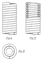
- Figs. 4 to 6 is essentially similar to that of Figs. 1 to 3, with the exception that only two helical metallic filaments are provided, both being wound in the same sense.
- the method of operation of the device is otherwise similar to that of Figs. 1 to 3.
- the device of Figs. 7 to 9 comprises a single helical metallic compression spring 6, at one end of which is located a circular pressure plate 7.
- the other end of the spring is enclosed within a generally cylindrical end cap 8 the internal surface of which is in rubbing contact with the outer periphery of the adjacent helices of the spring.
- compression of the end cap towards the pressure plate 7 and/or relative angular movement of the pressure plate 7 and end cap 8 is effective to cause friction between the contacting metallic surfaces, in order to activate crystallisation of the surrounding super-cooled liquid.
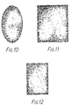
- Figs. 10 to 12 show activators comprising randomly convoluted metallic filament, such as wire wool, forming a body of material the compression and/or flexing of which is sufficient to effect crystallisation of the surrounding liquid.
- the body of material forms a coherent structure having the shape illustrated, the structure being disposed within larger outer envelope of the heat pack itself.
- the filamentary material may be confined within a sleeve or apertured envelope of resilient rubber or like material in order to cover any sharp edges of the filamentary material and thus prevent puncture of the outer envelope of the heat pack, whilst allowing the required flexing of the activator assembly.
- the various embodiments of activator described above provide varying degrees of sensitivity of actuation. That is to say the degree of flexing of the actuator required to trigger crystallisation of a given solution will be less as the sensitivity is increased.
- the sensitivity of the activator device is increased by increasing the overall area of contact between metallic surfaces, reducing the localised areas of contact and/or increasing the local contact pressure.
- factors tending to increase sensitivity of the activator include: increased number of nested helices (Figs. 1 to 6); nested helices of opposite pitch (Figs. 1 to 3); reduced diameter of metal filament; tighter interengagement of windings of nested helices; smaller pitch of wound helix.
- the invention accordingly provides a reliable and versatile activator arrangement having a response capable of being tailored to suit the requirements of a given design of heat pack.
- the activator device according to the invention lends itself to being housed in a small compartment separate from, but in fluid communication with, the main compartment of a flexible walled container containing the working solution.
- the end cap 8 may be replaced by a metallic body located within the spring 6.
- the randomly convoluted filament may be woven in a regular manner.
Landscapes
- Engineering & Computer Science (AREA)
- Health & Medical Sciences (AREA)
- Thermal Sciences (AREA)
- Physics & Mathematics (AREA)
- Animal Behavior & Ethology (AREA)
- Veterinary Medicine (AREA)
- Biomedical Technology (AREA)
- Heart & Thoracic Surgery (AREA)
- Vascular Medicine (AREA)
- Life Sciences & Earth Sciences (AREA)
- Mechanical Engineering (AREA)
- General Health & Medical Sciences (AREA)
- Public Health (AREA)
- General Engineering & Computer Science (AREA)
- Thermotherapy And Cooling Therapy Devices (AREA)
- Auxiliary Devices For And Details Of Packaging Control (AREA)
- Processing And Handling Of Plastics And Other Materials For Molding In General (AREA)
- Surface Heating Bodies (AREA)
- Package Closures (AREA)
- Cookers (AREA)
- Electric Ovens (AREA)
Claims (10)
- Aktiviereinrichtung zum Auslösen der Kristallisation einer unterkühlten Lösung, in welcher die Einrichtung eintaucht, wobei diese Einrichtung ein gekrümmtes langgestrecktes metallisches Element (1,6) mit einer in Kontakt mit einer anderen metallischen Fläche (2,8) stehenden Seitenfläche derart aufweist, daß ein Reibungskontakt der Flächen infolge einer relativen Bewegung dazu dient, um die Kristallisation der unterkühlten Flüssigkeit auszulösen, dadurch gekennzeichnet, daß die Seitenfläche durch ein geknäuletes langgestrecktes metallisches Element (1,6) gebildet ist und in kontinuierlichem Kontakt mit einer anderen Metalloberfläche (6,8) steht, die durch ein damit zusammenpassendes metallisches Element gebildet wird, oder in Mehrfachkontakt mit der Oberfläche eines weiteren geknäuelten langgestreckten metallischen Elements steht, wobei die besagte relative Bewegung durch Biegen oder Zusammendrücken der Aktivierungseinrichtung induziert wird.
- Wärmebeutel mit einem eine flexible Wand aufweisenden Behälter mit einer darin enthaltenen unterkühlbaren Lösung und einer Aktiviereinrichtung, wobei die Aktiviereinrichtung ein gekrümmtes langgestrecktes metallisches Element (1,6) in Kontakt mit einer anderen Metallfläche (2,8) derart aufweist, daß eine relative Bewegung des Elements und der Flache und ein entsprechender Reibungskontakt zwischen beiden wirksam wird, um eine Kristallisation der Lösung aus dem unterkühlten Zustand auszulösen, dadurch gekennzeichnet, daß die Aktiviereinrichtung eine in sich abgeschlossene, in die Lösung eingetauchte Einrichtung ist und daß der Reibungskontakt dadurch verursacht wird, daß die Aktiviereinrichtung durch die Containerwand hindurch derart manipuliert wird, daß ein Verbiegen oder ein Zusammendrücken stattfindet.
- Vorrichtung nach Anspruch 1 oder Heizbeutel nach Anspruch 2, dadurch gekennzeichnet, daß die Aktiviereinrichtung eine Anordnung von zwei oder mehr langgestreckten Elementen (1,2,3; Figuren 4 bis 6) aufweist, die jeweils schraubenförmig gewunden und ineinander verschachtelt angeordnet sind.
- Vorrichtung oder Heizbeutel nach Anspruch 3, dadurch gekennzeichnet, daß jede Schraubenwicklung (Figuren 4 bis 6) in einem Sinn gewickelt ist, der entgegengesetzt zu dem Wickelsinn einer benachbarten inneren oder äußeren Schraubenwicklung verläuft.
- Vorrichtung oder Heizbeutel nach Anspruch 3, dadurch gekennzeichnet, daß jede Schraubenwicklung (1,2,3) im gleichen Sinn gewickelt ist wie jede anschließende innere und/oder äußere Schraubenwicklung.
- Vorrichtung oder Heizbeutel nach Anspruch 3, 4 oder 5, dadurch gekennzeichnet, daß der Durchmesser jedes schraubenförmig gewickelten Elements in Richtung der Längsachse der Anordnung reduziert ist.
- Vorrichtung nach Anspruch 1 oder Heizbeutel nach Anspruch 2, dadurch gekennzeichnet, daß das geknäuelte langgestreckte metallische Element die Form einer Kompressionsfeder (6) aufweist und daß das dazu passende Element eine Kappe (8) oder ein Einsatz mit einer Oberfläche ist, die in einem einnestenden Kontakt mit Schraubenwicklungen am Endabschnitt der Feder (6) steht.
- Vorrichtung nach Anspruch 1 oder Heizbeutel nach Anspruch 2, dadurch gekennzeichnet, daß sie eine Vielzahl von langgestreckten Elementen umfaßt, die in einer zufälligen Verteilung verknäuelt oder verwoben sind (Figuren 10 bis 12).
- Vorrichtung nach Anspruch 1 oder Heizbeutel nach Anspruch 2, dadurch gekennzeichnet, daß die Auslöse- oder oder Aktiviereinrichtung in einer Hülse oder einer mit Öffnungen versehenen Umhüllung aus flexiblem Material angeordnet ist, welche einen Kontakt der Aktiviereinrichtung mit der unterkühlten Flüssigkeit gestatten.
- Heizbeutel der eine Aktiviereinrichtung inkorporiert, nach Anspruch 1 oder irgendene Ansprüche 5 zu 8 daran angehängt.
Priority Applications (1)
| Application Number | Priority Date | Filing Date | Title |
|---|---|---|---|
| AT86904898T ATE68954T1 (de) | 1985-08-28 | 1986-08-26 | Anregevorrichtung fuer einen heizbeutel. |
Applications Claiming Priority (2)
| Application Number | Priority Date | Filing Date | Title |
|---|---|---|---|
| GB858521349A GB8521349D0 (en) | 1985-08-28 | 1985-08-28 | Trigger device for heat pack |
| GB8521349 | 1985-08-28 |
Publications (2)
| Publication Number | Publication Date |
|---|---|
| EP0270540A1 EP0270540A1 (de) | 1988-06-15 |
| EP0270540B1 true EP0270540B1 (de) | 1991-10-30 |
Family
ID=10584345
Family Applications (1)
| Application Number | Title | Priority Date | Filing Date |
|---|---|---|---|
| EP86904898A Expired - Lifetime EP0270540B1 (de) | 1985-08-28 | 1986-08-26 | Anregevorrichtung für einen heizbeutel |
Country Status (9)
| Country | Link |
|---|---|
| US (1) | US4829980A (de) |
| EP (1) | EP0270540B1 (de) |
| JP (1) | JPS63501480A (de) |
| AT (1) | ATE68954T1 (de) |
| AU (1) | AU6281486A (de) |
| DE (1) | DE3682290D1 (de) |
| GB (1) | GB8521349D0 (de) |
| NZ (1) | NZ217369A (de) |
| WO (1) | WO1987001275A1 (de) |
Cited By (1)
| Publication number | Priority date | Publication date | Assignee | Title |
|---|---|---|---|---|
| RU2128972C1 (ru) * | 1997-06-10 | 1999-04-20 | Общество с ограниченной ответственностью "Дельта-Терм" | Способ изготовления активатора для термохимической грелки |
Families Citing this family (18)
| Publication number | Priority date | Publication date | Assignee | Title |
|---|---|---|---|---|
| US4860729A (en) * | 1988-02-10 | 1989-08-29 | Midwest Research Institute | Method and apparatus for nucleating the crystallization of undercooled materials |
| WO1989010520A1 (en) * | 1988-04-22 | 1989-11-02 | Hettel Bernd R | Supercooled liquid thermal generator and improved triggering device |
| JPH01274838A (ja) * | 1988-04-25 | 1989-11-02 | Nok Corp | 過冷却液体の任意固化装置 |
| US5056589A (en) * | 1989-12-19 | 1991-10-15 | Hettel Bernd R | Supercooled liquid thermal generator and improved triggering device |
| US5178139A (en) * | 1990-03-05 | 1993-01-12 | Stephen P. Angelillo | Absorbent pad and thermal pack |
| US5275156A (en) * | 1992-07-13 | 1994-01-04 | Nova Design Partners, L.P. | Reusable heat releasing pack |
| JP2943609B2 (ja) * | 1994-06-21 | 1999-08-30 | トヨタ自動車株式会社 | 蓄熱装置 |
| US5736110A (en) * | 1995-05-16 | 1998-04-07 | Angelillo; Stephen P. | Activator for initiating crystallization of a supersaturated solution |
| US5645749A (en) * | 1995-08-04 | 1997-07-08 | Wang; Charles | Heat pack capable of being recharged by microwave energy |
| FR2770627B1 (fr) * | 1997-10-30 | 2000-01-21 | Ali Nicolas Menault | Declencheur pour chaufferette a liquide en surfusion |
| DE19901392C2 (de) * | 1998-11-19 | 2003-02-27 | Chang Pyoung Baik | Wärmepackung |
| KR200178505Y1 (ko) | 1998-11-19 | 2000-04-15 | 백창평 | 히트 팩 |
| US20040065314A1 (en) * | 2000-07-20 | 2004-04-08 | Layer James H. | Apparatus, systems, and methods for warming materials |
| KR100411545B1 (ko) * | 2001-03-29 | 2003-12-18 | 백창평 | 히트팩용 트리거 |
| US7151157B2 (en) * | 2004-03-04 | 2006-12-19 | University Of Connecticut | Mechanically activated shape memory device |
| US9593594B2 (en) | 2014-09-30 | 2017-03-14 | General Electric Company | Method and apparatus for decongealing a lubricating fluid in a heat exchanger apparatus |
| US20180017337A1 (en) * | 2016-07-15 | 2018-01-18 | Neothermal Energy Storage Inc. | Thermal energy storage apparatus |
| US11435146B2 (en) | 2019-03-07 | 2022-09-06 | Neothermal Energy Storage Inc. | Thermal energy storage apparatus |
Family Cites Families (10)
| Publication number | Priority date | Publication date | Assignee | Title |
|---|---|---|---|---|
| GB375521A (en) * | 1931-06-05 | 1932-06-30 | Ralph Summerfield Ferguson | Improvements in chemical heating appliances |
| US1915523A (en) * | 1931-10-13 | 1933-06-27 | Ralph S Ferguson | Valve mechanism for heat flasks |
| DE599756C (de) * | 1931-11-10 | 1934-07-09 | Franz Zabinski | Geschlossene Waermflasche mit einer kristallisationsfaehigen |
| US2220777A (en) * | 1939-02-01 | 1940-11-05 | Donald F Othmer | Valveless chemical heater |
| US4077390A (en) * | 1976-08-02 | 1978-03-07 | Marc F. Fiedler | Reusable heat pack containing supercooled solution and means for activating same |
| US4295517A (en) * | 1978-06-16 | 1981-10-20 | Woldemar Guex | Reusable heat devices containing xylitol as the heat-storage material |
| US4379448A (en) * | 1980-01-18 | 1983-04-12 | Kapralis Imants P | Trigger to initiate crystallization |
| US4460546A (en) * | 1980-08-11 | 1984-07-17 | Kapralis Imants P | Trigger to controllably initiate crystallization |
| US4580547A (en) * | 1984-06-04 | 1986-04-08 | Kapralis Imants P | Flexible heat pack containing super cooled salt solution |
| US4587950A (en) * | 1984-12-31 | 1986-05-13 | Clairol Incorporated | Heat pack apparatus |
-
1985
- 1985-08-28 GB GB858521349A patent/GB8521349D0/en active Pending
-
1986
- 1986-08-26 AU AU62814/86A patent/AU6281486A/en not_active Abandoned
- 1986-08-26 DE DE8686904898T patent/DE3682290D1/de not_active Expired - Lifetime
- 1986-08-26 JP JP61504578A patent/JPS63501480A/ja active Pending
- 1986-08-26 US US07/052,737 patent/US4829980A/en not_active Expired - Fee Related
- 1986-08-26 EP EP86904898A patent/EP0270540B1/de not_active Expired - Lifetime
- 1986-08-26 WO PCT/GB1986/000506 patent/WO1987001275A1/en not_active Ceased
- 1986-08-26 AT AT86904898T patent/ATE68954T1/de not_active IP Right Cessation
- 1986-08-27 NZ NZ217369A patent/NZ217369A/xx unknown
Cited By (1)
| Publication number | Priority date | Publication date | Assignee | Title |
|---|---|---|---|---|
| RU2128972C1 (ru) * | 1997-06-10 | 1999-04-20 | Общество с ограниченной ответственностью "Дельта-Терм" | Способ изготовления активатора для термохимической грелки |
Also Published As
| Publication number | Publication date |
|---|---|
| WO1987001275A1 (en) | 1987-03-12 |
| DE3682290D1 (de) | 1991-12-05 |
| AU6281486A (en) | 1987-03-24 |
| EP0270540A1 (de) | 1988-06-15 |
| GB8521349D0 (en) | 1985-10-02 |
| US4829980A (en) | 1989-05-16 |
| JPS63501480A (ja) | 1988-06-09 |
| NZ217369A (en) | 1988-09-29 |
| ATE68954T1 (de) | 1991-11-15 |
Similar Documents
| Publication | Publication Date | Title |
|---|---|---|
| EP0270540B1 (de) | Anregevorrichtung für einen heizbeutel | |
| HU194742B (en) | Insert for containers of explosion risk having at least one pouring inlet or one outlet | |
| JPS6028557B2 (ja) | 配管工用可撓性清掃用具 | |
| US3507069A (en) | Casting rod | |
| US3498369A (en) | Heat pipes with prefabricated grooved capillaries and method of making | |
| US5056589A (en) | Supercooled liquid thermal generator and improved triggering device | |
| JPS621561B2 (de) | ||
| US2893563A (en) | Strainer | |
| JPH07163867A (ja) | 新規なパッキングエレメント | |
| US2912133A (en) | Rubbish burner | |
| KR890012050A (ko) | 플라스틱 단부부품을 갖는 금속정호스크린과 그 부착방법 | |
| EP1116880A3 (de) | Anlasser mit elastischem Schubhebel zum Antrieb des Anlassritzels | |
| US3258990A (en) | Push-pull cable | |
| EP0269689A1 (de) | Aktivierung eines phaseumwandlungsmediums | |
| US2442360A (en) | Tubular remote-control device | |
| US2451065A (en) | Electrolytic water correction device | |
| EP0041095B1 (de) | Verfahren zum Belasten einer Feder mit konstanter Kennlinie, insbesondere für Farbbandkassetten von Schreibmaschinen | |
| GB1589407A (en) | Flexible transmission system | |
| US2655012A (en) | Flexible shaft | |
| US20050077223A1 (en) | Water treatment system | |
| WO1989010520A1 (en) | Supercooled liquid thermal generator and improved triggering device | |
| RU98104435A (ru) | Однопрядевый анкер | |
| RU95122820A (ru) | Стыковочная головка для телекоммуникационных изолированных проводов | |
| RU2004396C1 (ru) | Защитное устройство | |
| US3038540A (en) | Devices for cleaning the walls of boreholes |
Legal Events
| Date | Code | Title | Description |
|---|---|---|---|
| PUAI | Public reference made under article 153(3) epc to a published international application that has entered the european phase |
Free format text: ORIGINAL CODE: 0009012 |
|
| 17P | Request for examination filed |
Effective date: 19880322 |
|
| AK | Designated contracting states |
Kind code of ref document: A1 Designated state(s): AT BE CH DE FR GB IT LI NL SE |
|
| 17Q | First examination report despatched |
Effective date: 19900309 |
|
| RAP3 | Party data changed (applicant data changed or rights of an application transferred) |
Owner name: CREWSAVER LIMITED |
|
| GRAA | (expected) grant |
Free format text: ORIGINAL CODE: 0009210 |
|
| AK | Designated contracting states |
Kind code of ref document: B1 Designated state(s): AT BE CH DE FR GB IT LI NL SE |
|
| PG25 | Lapsed in a contracting state [announced via postgrant information from national office to epo] |
Ref country code: LI Effective date: 19911030 Ref country code: CH Effective date: 19911030 |
|
| REF | Corresponds to: |
Ref document number: 68954 Country of ref document: AT Date of ref document: 19911115 Kind code of ref document: T |
|
| REF | Corresponds to: |
Ref document number: 3682290 Country of ref document: DE Date of ref document: 19911205 |
|
| ET | Fr: translation filed | ||
| RBV | Designated contracting states (corrected) |
Designated state(s): BE CH DE FR GB LI NL |
|
| REG | Reference to a national code |
Ref country code: CH Ref legal event code: PL |
|
| PLBE | No opposition filed within time limit |
Free format text: ORIGINAL CODE: 0009261 |
|
| STAA | Information on the status of an ep patent application or granted ep patent |
Free format text: STATUS: NO OPPOSITION FILED WITHIN TIME LIMIT |
|
| 26N | No opposition filed | ||
| REG | Reference to a national code |
Ref country code: FR Ref legal event code: TP |
|
| NLS | Nl: assignments of ep-patents |
Owner name: E. JESKE |
|
| REG | Reference to a national code |
Ref country code: GB Ref legal event code: 732E |
|
| PGFP | Annual fee paid to national office [announced via postgrant information from national office to epo] |
Ref country code: GB Payment date: 19990809 Year of fee payment: 14 |
|
| PGFP | Annual fee paid to national office [announced via postgrant information from national office to epo] |
Ref country code: FR Payment date: 19990817 Year of fee payment: 14 |
|
| PGFP | Annual fee paid to national office [announced via postgrant information from national office to epo] |
Ref country code: BE Payment date: 19990820 Year of fee payment: 14 |
|
| PGFP | Annual fee paid to national office [announced via postgrant information from national office to epo] |
Ref country code: NL Payment date: 19990823 Year of fee payment: 14 |
|
| PG25 | Lapsed in a contracting state [announced via postgrant information from national office to epo] |
Ref country code: GB Free format text: LAPSE BECAUSE OF NON-PAYMENT OF DUE FEES Effective date: 20000826 |
|
| PG25 | Lapsed in a contracting state [announced via postgrant information from national office to epo] |
Ref country code: BE Free format text: LAPSE BECAUSE OF NON-PAYMENT OF DUE FEES Effective date: 20000831 |
|
| BERE | Be: lapsed |
Owner name: JESKE ERICH Effective date: 20000831 |
|
| PG25 | Lapsed in a contracting state [announced via postgrant information from national office to epo] |
Ref country code: NL Free format text: LAPSE BECAUSE OF NON-PAYMENT OF DUE FEES Effective date: 20010301 |
|
| GBPC | Gb: european patent ceased through non-payment of renewal fee |
Effective date: 20000826 |
|
| PG25 | Lapsed in a contracting state [announced via postgrant information from national office to epo] |
Ref country code: FR Free format text: LAPSE BECAUSE OF NON-PAYMENT OF DUE FEES Effective date: 20010430 |
|
| NLV4 | Nl: lapsed or anulled due to non-payment of the annual fee |
Effective date: 20010301 |
|
| REG | Reference to a national code |
Ref country code: FR Ref legal event code: ST |
|
| PGFP | Annual fee paid to national office [announced via postgrant information from national office to epo] |
Ref country code: DE Payment date: 20050727 Year of fee payment: 20 |