EP0270331B1 - Besetzungsdetektoren etc. - Google Patents
Besetzungsdetektoren etc. Download PDFInfo
- Publication number
- EP0270331B1 EP0270331B1 EP87310541A EP87310541A EP0270331B1 EP 0270331 B1 EP0270331 B1 EP 0270331B1 EP 87310541 A EP87310541 A EP 87310541A EP 87310541 A EP87310541 A EP 87310541A EP 0270331 B1 EP0270331 B1 EP 0270331B1
- Authority
- EP
- European Patent Office
- Prior art keywords
- housing
- occupancy sensor
- sensor device
- barrier
- spring member
- Prior art date
- Legal status (The legal status is an assumption and is not a legal conclusion. Google has not performed a legal analysis and makes no representation as to the accuracy of the status listed.)
- Expired - Lifetime
Links
Images
Classifications
-
- G—PHYSICS
- G08—SIGNALLING
- G08B—SIGNALLING SYSTEMS, e.g. PERSONAL CALLING SYSTEMS; ORDER TELEGRAPHS; ALARM SYSTEMS
- G08B13/00—Burglar, theft or intruder alarms
- G08B13/18—Actuation by interference with heat, light, or radiation of shorter wavelength; Actuation by intruding sources of heat, light, or radiation of shorter wavelength
- G08B13/189—Actuation by interference with heat, light, or radiation of shorter wavelength; Actuation by intruding sources of heat, light, or radiation of shorter wavelength using passive radiation detection systems
- G08B13/19—Actuation by interference with heat, light, or radiation of shorter wavelength; Actuation by intruding sources of heat, light, or radiation of shorter wavelength using passive radiation detection systems using infrared-radiation detection systems
-
- F—MECHANICAL ENGINEERING; LIGHTING; HEATING; WEAPONS; BLASTING
- F16—ENGINEERING ELEMENTS AND UNITS; GENERAL MEASURES FOR PRODUCING AND MAINTAINING EFFECTIVE FUNCTIONING OF MACHINES OR INSTALLATIONS; THERMAL INSULATION IN GENERAL
- F16B—DEVICES FOR FASTENING OR SECURING CONSTRUCTIONAL ELEMENTS OR MACHINE PARTS TOGETHER, e.g. NAILS, BOLTS, CIRCLIPS, CLAMPS, CLIPS OR WEDGES; JOINTS OR JOINTING
- F16B2/00—Friction-grip releasable fastenings
- F16B2/20—Clips, i.e. with gripping action effected solely by the inherent resistance to deformation of the material of the fastening
- F16B2/22—Clips, i.e. with gripping action effected solely by the inherent resistance to deformation of the material of the fastening of resilient material, e.g. rubbery material
- F16B2/24—Clips, i.e. with gripping action effected solely by the inherent resistance to deformation of the material of the fastening of resilient material, e.g. rubbery material of metal
- F16B2/241—Clips, i.e. with gripping action effected solely by the inherent resistance to deformation of the material of the fastening of resilient material, e.g. rubbery material of metal of sheet metal
- F16B2/245—Clips, i.e. with gripping action effected solely by the inherent resistance to deformation of the material of the fastening of resilient material, e.g. rubbery material of metal of sheet metal external, i.e. with contracting action
- F16B2/246—Clips, i.e. with gripping action effected solely by the inherent resistance to deformation of the material of the fastening of resilient material, e.g. rubbery material of metal of sheet metal external, i.e. with contracting action the clip being released by tilting the clip or a part thereof to a position in which the axis of the openings surrounding the gripped elements is parallel to, or coincides with, the axis of the gripped elements
-
- F—MECHANICAL ENGINEERING; LIGHTING; HEATING; WEAPONS; BLASTING
- F16—ENGINEERING ELEMENTS AND UNITS; GENERAL MEASURES FOR PRODUCING AND MAINTAINING EFFECTIVE FUNCTIONING OF MACHINES OR INSTALLATIONS; THERMAL INSULATION IN GENERAL
- F16B—DEVICES FOR FASTENING OR SECURING CONSTRUCTIONAL ELEMENTS OR MACHINE PARTS TOGETHER, e.g. NAILS, BOLTS, CIRCLIPS, CLAMPS, CLIPS OR WEDGES; JOINTS OR JOINTING
- F16B21/00—Means for preventing relative axial movement of a pin, spigot, shaft or the like and a member surrounding it; Stud-and-socket releasable fastenings
- F16B21/10—Means for preventing relative axial movement of a pin, spigot, shaft or the like and a member surrounding it; Stud-and-socket releasable fastenings by separate parts
- F16B21/20—Means for preventing relative axial movement of a pin, spigot, shaft or the like and a member surrounding it; Stud-and-socket releasable fastenings by separate parts for bolts or shafts without holes, grooves, or notches for locking members
-
- Y—GENERAL TAGGING OF NEW TECHNOLOGICAL DEVELOPMENTS; GENERAL TAGGING OF CROSS-SECTIONAL TECHNOLOGIES SPANNING OVER SEVERAL SECTIONS OF THE IPC; TECHNICAL SUBJECTS COVERED BY FORMER USPC CROSS-REFERENCE ART COLLECTIONS [XRACs] AND DIGESTS
- Y10—TECHNICAL SUBJECTS COVERED BY FORMER USPC
- Y10S—TECHNICAL SUBJECTS COVERED BY FORMER USPC CROSS-REFERENCE ART COLLECTIONS [XRACs] AND DIGESTS
- Y10S250/00—Radiant energy
- Y10S250/01—Passive intrusion detectors
Definitions
- This invention relates to occupancy detectors.
- US patent specification 4087688 discloses such an occupancy detector having a long entry neck internally coated with reflective material as a lightpath; and multiple reflections of received radiation going to its sensor effectively define selected sub-areas of an overall field of view for monitoring by the sensor.
- European patent specification 0025983 has a much shorter reflective entry neck or "lightpath" through the thickness of a metal plate carrying a rearward filter for radiation going to a spaced infra-red sensor in a thermally insulating mount so as to reduce spurious detection.
- This invention also prefers use of reflective and/or refractive "lightpaths" but is directed to further useful contribution by means affording such lightpaths.
- an occupancy sensor device comprising a housing having an opening as a neck, and an infra-red sensor located recessed in the housing to receive radiation from a lightpath bounded by interior surface of said neck; characterised in that said neck is afforded by a tube member in an aperture in said housing, etc), said tube member being of electrically insulating material carrying electrically conducting material and being angularly movable selectively to make electrical connections for the device via said electrically conducting material).
- the housing neck is preferably as an insert tube and carries conductive material for making electrical connections relative to a circuit board, typically preferably at its inboard end and as a coating, selectively interconnecting contacts on the end of the circuit board, depending on the angular position of the tube which may be adjusted from outside the housing.
- the contacts can usefully serve in conjunction with appropriate electronic circuitry to reduce a reset period of the occupancy sensor device for test purposes.
- a particular preferred elongate occupancy sensor housing has separable inner and outer parts with longitudinal formations from one end of the inner part to accommodate edges of a (or said) printed circuit board carrying the control sensor at one end. Where the formations are slots, the outer part may engage closely over the inner part to close the slots clampingly onto edges of the circuit board.
- a suitable outer part is generally cylindrical and opens only at one end save for wire access provision.
- a suitable inner part is flanged at its other end. For such parts, the flange of the inner part may butt onto the open end of the outer part.
- Refractive or reflective properties of the interior of said neck can usefully serve to improve effective field of view of the sensor.
- One or more supplementary performance modifiers may be fitted to the sensor construction at the entry to the lightpath, say as a lens or reflective cowl to affect field of view. Performance modifiers may be used that additionally or alternatively alter operating spectrums for received signals.
- transparent or translucent refractive systems can be fitted in or across the lightpath and/or one or more reflective surfaces define a boundary or entry for the lightpath.
- Preferred infra-red sensitive sensors have associated signalling means capable of transmitting a signal or a series of signals when an operating source of infra-red radiation is detected. These signals may go onto wiring to a control unit for operating an alarm and/or switching on lights.
- An aspect of invention of wider application concerns fixing an object, such as an occupancy detector, in abutment with an apertured barrier, such as a ceiling or ceiling tile, with a part of the object passing through an aperture in the barrier, and comprises using a resilient spring member to fit about and grip said part in its relaxed state but capable of flexing to be free of said part for moving towards the barrier at its other side and serving to hold the object in position, usefully then with abutment also of parts of the relaxed or partly relaxed spring member against such other side of the barrier.
- An object with a flange for abutment purposes is suitable, as applies to the preferred occupancy sensor housing hereof, and can afford a drawing or clenching or clamping action on the object relative to the barrier, particularly for aiding gap-less seating of the flange. Otherwise, retention of an elongate object could additionally include fitting one spring member on each side of the barrier.
- This aspect of invention has method, installed object, and spring member connotations.
- a preferred spring member comprises a deformable resilient member having an opening shaped so that said part can be loosely fitted through the opening only when the plate is flexed.
- a suitable spring member comprises an arcuate plate flexed as aforesaid by reduction of its curvature. Then, in order to allow such a plate to be more easily flexed, a pair of angled parts can extend from the arcuate part of the member in which the opening is formed, and may extend from one side of the arcuate plate away from said barrier at installation and be one at each end, so that bends or corners abut on said barrier as installed.
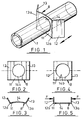
- FIG. 1 part of a plastics moulded sensor housing, is fitted with a resilient metal fixing spring member 8.
- the spring member 8 comprises a central arcuate part 11 with a pair of end parts 12, 13 extending from opposite straight edges of the plate 11 to bends 12a, 13a at ends of curvature of the central arcuate part 11.
- the spring member 8 is conveniently of unitary metal construction, made from centrally apertured plate bent to shape and set as appropriate.
- the spring member 8 is shown in its relaxed state where a circular central hole appears elliptical (14a) in plan.
- the spring member 8 is shown in a flexed state. Equal but opposite compression forces, indicated by arrows F-F, are applied one to each of the end parts 12, 13 to bring them substantially parallel. Consequently the central part 11 becomes substantially flat and its central hole is circular in plan, see 14 b .
- the spring member 8 may be fixed to any circular housing having a diameter between its minimum and maximum diameters appearing elliptical.
- housings of other than circular cross-section can be secured if the opening in the spring member is correspondingly shaped.
- the action of relaxing the spring member 8 enables its bends 12a, 13a to draw the flanged end onto the barrier if the flexed spring member is butted to its other side.
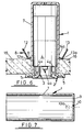
- Figure 6 shows an occupancy sensor in a vertical arrangement of the sensor housing 1; and with an aperture tube 2 fitted in its lower end, and an infra-red sensitive sensor system 4 fitted within the body of the housing 1 and vertically separated from the lower end of the aperture tube 2 by means of a spacer ring 3.
- the sensor housing 1 is fitted through a circular opening 15 in a suspended ceiling tile 16 and retained in that position by means of the fixing spring member 8 attached to the housing 1 above the ceiling 16.
- the housing 1 is vertically positioned so that a flange 5, on the lower end of the aperture tube 2, abuts with the underside of the ceiling tile 16 and is preferably drawn thereagainst by the corners 12a, 13a of the spring member.
- the sensor system 4 is conveniently on a printed circuit board carrying a sensor cell 4 a at one end and bearing electronic sensing circuitry.
- the sensor is shown diagrammatically and flanked by two contacts, preferably of curved spring leaf form see 4x, 4y.
- the electronic arrangement as such does not form part of the present invention, but the purpose of the contacts 4x, 4y is of interest as, once bridged, they will serve the purpose of automatically reducing a time interval otherwise effective for the circuitry to go to a reset condition after last sensing an occupant (as is particularly useful in controlling lighting systems). That reduction of interval particularly facilitates speedy testing after installation.
- the sensor housing 1 as seen in Figure 7, comprises a plastics moulded tube 7 closed at one end by an integrally moulded circular end wall 9.
- the plastics material may be of fire-resistant type.
- the housing 1 has an external diameter of approximately 42mm, an external length of approximately 110mm and a wall thickness of between approximately 2.0 and 2.5mm, and the spring member is of steel 0.2 to 1 mm plate measuring (as viewed in Figures 2 and 3) 60 mm in height, 50 mm in chordal width, 60 mm radius of curvature and a 43 mm diameter hole reducing to 41 mm minimum (elliptical).
- the circular end wall 9 has at least one opening 10, the area of which is large enough to accommodate one or more electrical power supply and/or signalling cables (not shown).
- a single hole concentric with the axis of the housing is formed in the circular end wall 9.
- Such a hole 10 has a diameter of between approximately 2 and 5 mm. If the distance between a false ceiling and a ceiling proper is only slightly greater than the length of the housing then any power supply hole or holes 10 could pass through the wall of the tube, say via knock-outs, see dashed at 10a.
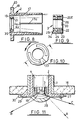
- the aperture tube 2 is also a moulded plastics structure, as seen in Figure 8. It generally comprises a sensor-retaining tube 17 shorter than the housing 1, say having a length of approximately 58.5mm in the specific example and having an external diameter, say of approximately 38mm, so that it is a close-fit, preferably a tight friction-fit, within the housing 1.
- the retaining tube 17 has an outer flange 18 and an inner aperture flange 19 integrally moulded at or near to its outer end.
- the outer flange 18 has a greater diameter than the housing 1, say approximately of 60 mm, and is shown with a continuously indented surface having an outwardly open groove 20 for retaining any optical performance modifiers in position across the lightpath.
- the aperture flange 19 surrounds an opening of lesser diameter than the housing 1, say of approximately 17 mm.
- the radially inward face of the aperture flange 19 is shown with an outwardly divergent conical surface to aid effective field of view, say at approximately 60 degrees.
- an integrally moulded retaining lip 21 which projects a short distance from the flange 19 and serves to retain the spacer ring 3 in position, say with minimum and maximum diameters of approximately 22 mm and 26.5 mm for the lip 21.
- the inside face of the sensor retaining tube 17 is shown as being slightly conical from a point approximately 17 mm from its aperture end, so that the internal diameter of the tube 17 is slightly greater at the interior end than at the centre, say with an angle of divergence of approximately 1 degree.
- the spacer ring 3 which may have a maximum diameter of approximately 33 mm and a length of approximately 14.5 mm in the specific example, is seen in cross section.
- the spacer ring 3 consists of a plastics (say ABS) moulded construction comprising an inner ring 22, say with a minimum diameter of approximately 17 mm, coaxial with but separated from an outer ring 23 by means of an annular rib 24.
- the channel 25 formed at the aperture end between the walls 22, 23 and the rib 24 is adapted to receive the lip 21 on the inside of the aperture flange 19 so that the aperture tube 2 and the spacer ring 3 can be firmly and accurately held together.
- the inward face of the inner ring 22 is shown covered with a thin reflective metal coating 26, say of either chrome or a predominantly chrome-based alloy having a thickness of approximately 0.04 mm.
- the coating 26 covers not only the entire inward face but also at least into the inner end face at 26E.
- the function of the reflective coating 26 is to increase the field of view of the sensor (as illustrated in Figure 11), and the function of the end coating 26E is to selectively interconnect the contacts 4x, 4y.
- Figure 11 is similar to Figure 6 and components common to both drawings will not be described afresh.
- An infra-red sensitive sensor construction is arranged to be fitted through a vertical opening in a false ceiling 16.
- An aperture tube 2, having a flange 5 which abuts with the ceiling 16, is incorporated into the construction and has a substantially transparent refractive performance modifier 27 fitted to it.
- the refractive performance modifier 27 comprises a convex lens portion 28 fitted coaxially across the lightpath, an annular plate 29 integral with the circumferential edge of the convex lens portion, and a flange 30 integral with and upwardly projecting from the outer edge of the annular plate 29 so that a ridge 31 inwardly projecting from the flange 30 can fit into an outwardly open groove 20 formed in the outer flange 18 of the aperture tube 2.
- a refractive performance modifier increases the field of view. It will of course be appreciated that the actual field of view may be readily determined for any particular example.
- Arrow “A” represents a lightray situated at the extreme edge of the field of view of a sensor construction which does not incorporate a refractive or a reflective optical performance modifier.
- Arrow “B” represents a lightray situated close to the extreme edge of the field of view of a sensor construction incorporating only a refractive optical performance modifier.
- Arrow “C” represents a lightray situated close to the extreme edge of the field of view of a sensor construction incorporating only a reflective optical performance modifier.
- a considerable increase in the field of view of a sensor construction may be effected by incorporating a refractive and/or a reflective optical performance modifier.
- the sensor cell may be sensitive to forms of electromagnetic radiation other than infra-red radiation.
Landscapes
- Engineering & Computer Science (AREA)
- General Engineering & Computer Science (AREA)
- Physics & Mathematics (AREA)
- General Physics & Mathematics (AREA)
- Mechanical Engineering (AREA)
- Geophysics And Detection Of Objects (AREA)
- Burglar Alarm Systems (AREA)
- Investigating Or Analysing Materials By Optical Means (AREA)
- Preparation Of Compounds By Using Micro-Organisms (AREA)
- Transforming Light Signals Into Electric Signals (AREA)
- Non-Silver Salt Photosensitive Materials And Non-Silver Salt Photography (AREA)
Claims (10)
- Besetzungsabtastvorrichtung mit einem Gehäuse (1 usw.), das eine Öffnung, wie einen Hals (3), und einen Infrarotsensor (4a) aufweist, der in einer Ausnehmung im Gehäuse angeordnet ist, um Strahlung von einem Lichtweg aufzunehmen, der durch die Innenfläche (26) des Halses (3) begrenzt ist; dadurch gekennzeichnet, daß der Hals (3) von einem Rohrteil (22-24) in einer Öffnung in dem Gehäuse (1 usw.) gebildet ist, wobei das Rohrteil (22-24) aus elektrisch isolierendem Material besteht, welches elektrisch leitendes Material (26E) trägt und wahlweise in Winkelrichtung bewegbar ist, um elektrische Verbindungen (4x,4y) für die Vorrichtung über das elektrisch leitende Material herzustellen.
- Besetzungsabtastvorrichtung nach Anspruch 1, bei welcher die Innenfläche (26) des Halses (3) reflektierende und/oder brechende Eigenschaften für empfangene Infrarotstrahlung aufweist, die vom Sensor (4a) abgetastet werden soll.
- Besetzungsabtastvorrichtung nach Anspruch 1 oder 2, bei welcher das Rohrteil (22-24) ein drehbarer Einsatz im Gehäuse (1 usw.) ist, der von der Außenseite des Gehäuses (1 usw.) drehbar ist und dessen nach innen weisendes Ende mit elektrisch leitendem Material (26E) beschichtet und so ausgebildet ist (33), daß die selektiven Verbindungen (4x,4y) bezüglich der Kontakte einer Schaltplatte (4) innerhalb des Gehäuses (1 usw.) gebildet werden.
- Besetzungsabtastvorrichtung nach Anspruch 1, 2 oder 3, bei welcher eine wählbare leitende Verbindung zu Testzwecken dient, indem eine normale Rückstellperiode für die Vorrichtung verkürzt wird.
- Besetzungsabtastvorrichtung nach einem der vorangehenden Ansprüche, bei welcher das Gehäuse (bei 5) eine Stelle zum Einpassen eines zusätzlichen Strahlungsleistungsmodifizierers (30) an seiner den Einlaß zu dem Lichtweg bildenden Öffnung (19) bietet.
- Besetzungsabtastvorrichtung nach einem der vorangehenden Ansprüche, bei welcher das Gehäuse einen inneren Teil (2) und einen äußeren Teil (1) aufweist, die voneinander trennbar sind, und der innere Teil (2) längsverlaufende Gebilde (17a) zur Aufnahme der Ränder einer gedruckten Schaltung (4) aufweist, wie die den Sensor (4a) an einem Ende tragende gedruckte Schaltungsplatte (4).
- Besetzungsabtastvorrichtung nach Anspruch 6, bei welcher die längsverlaufenden Gebilde Schlitze (17a) sind, die von einem Ende des inneren Teils (2) ausgehen, und der äuBere Teil (1) den inneren Teil (2) eng umschließt, um die Schlitze (17) auf den Rändern der gedruckten Schaltungsplatte (4) dichtend zu verschließen.
- Besetzungsabtastvorrichtung nach einem der vorangehenden Ansprüche, bei welcher das Gehäuse (1,2) einen Flansch (5) zur Anlage nahe der Umrandung einer Öffnung in einer Trennwand (16), durch welche der Teil (1) des Gehäuses durchtritt, aufweist, und ferner mit einem elastischen Federteil (11), der in seinem entspannten Zustand auf dem Teil (1) sitzt und diesen umgreift, jedoch so gebogen werden kann, daß er vom Teil (1) freikommt und zur Trennwand (16) auf der gegenüberliegenden Seite bezüglich derjenigen, an welcher der Flansch angelegt wird, verschoben werden kann und zum Halten des Gehäuses (1,2) in der gewünschten Anlagestellung dient.
- Besetzungsabtastvorrichtung nach Anspruch 8, bei welcher nach dem Einbau in die Trennwand (16) der Federteil (11) eine positive Abdichtwirkung ausübt.
- Besetzungsabtastvorrichtung nach Anspruch 8 oder 9, bei welcher der Federteil eine gebogene Federplatte (11) mit einer Öffnung (14) zum Ergreifen und Loslassen des Teils (1) des Gehäuses je nach dem Biegezustand der Federplatte (11) ist.
Applications Claiming Priority (4)
| Application Number | Priority Date | Filing Date | Title |
|---|---|---|---|
| GB8628635 | 1986-12-01 | ||
| GB868628635A GB8628635D0 (en) | 1986-12-01 | 1986-12-01 | Fixing occupancy detector |
| GB8705138 | 1987-03-05 | ||
| GB878705138A GB8705138D0 (en) | 1987-03-05 | 1987-03-05 | Occupancy detector etc |
Related Child Applications (1)
| Application Number | Title | Priority Date | Filing Date |
|---|---|---|---|
| EP93202278.3 Division-Into | 1993-08-02 |
Publications (3)
| Publication Number | Publication Date |
|---|---|
| EP0270331A2 EP0270331A2 (de) | 1988-06-08 |
| EP0270331A3 EP0270331A3 (en) | 1989-12-13 |
| EP0270331B1 true EP0270331B1 (de) | 1995-05-03 |
Family
ID=26291621
Family Applications (2)
| Application Number | Title | Priority Date | Filing Date |
|---|---|---|---|
| EP87310541A Expired - Lifetime EP0270331B1 (de) | 1986-12-01 | 1987-11-30 | Besetzungsdetektoren etc. |
| EP19930202278 Withdrawn EP0571052A1 (de) | 1986-12-01 | 1987-11-30 | Besetzungsdetektoren |
Family Applications After (1)
| Application Number | Title | Priority Date | Filing Date |
|---|---|---|---|
| EP19930202278 Withdrawn EP0571052A1 (de) | 1986-12-01 | 1987-11-30 | Besetzungsdetektoren |
Country Status (6)
| Country | Link |
|---|---|
| US (1) | US4847501A (de) |
| EP (2) | EP0270331B1 (de) |
| AT (1) | ATE122167T1 (de) |
| CA (1) | CA1285043C (de) |
| DE (1) | DE3751277D1 (de) |
| GB (1) | GB2199659B (de) |
Families Citing this family (8)
| Publication number | Priority date | Publication date | Assignee | Title |
|---|---|---|---|---|
| FR2644666B1 (fr) * | 1989-03-15 | 1991-06-21 | Legrand Sa | Cellule receptrice pour commande a distance |
| FR2713722B1 (fr) * | 1993-12-14 | 1996-01-19 | Rapid Sa | Pince à fixation sur un élément allongé tel qu'une tige. |
| US6715246B1 (en) * | 1999-08-10 | 2004-04-06 | Armstrong World Industries, Inc. | Ceiling tile transmitter and receiver system |
| US8199010B2 (en) * | 2009-02-13 | 2012-06-12 | Lutron Electronics Co., Inc. | Method and apparatus for configuring a wireless sensor |
| DE102015102645A1 (de) * | 2015-02-25 | 2016-08-25 | Insta Elektro Gmbh | Melder |
| DE102015102646A1 (de) * | 2015-02-25 | 2016-08-25 | Insta Elektro Gmbh | Melder |
| US10798797B1 (en) * | 2016-03-28 | 2020-10-06 | Douglas Lighting Controls | Ceiling mount sensor assembly |
| US11255897B2 (en) * | 2018-10-01 | 2022-02-22 | Cisco Technology, Inc. | Adjustable anchor for printed circuit board environmental sensor |
Family Cites Families (15)
| Publication number | Priority date | Publication date | Assignee | Title |
|---|---|---|---|---|
| DE1237385B (de) * | 1964-10-15 | 1967-03-23 | Raymond A | Klemmbuegel zur Befestigung von Kabeln od. dgl. mittels Dornen an gelochten Traegern |
| US3492058A (en) * | 1967-02-03 | 1970-01-27 | Gen Dynamics Corp | Detector lens assembly |
| DE2103909C3 (de) * | 1970-02-06 | 1983-04-07 | Hörmann GmbH, 8000 München | Überwachungseinrichtung zur Feststellung eines Eindringlings, |
| FR2199579A1 (de) * | 1972-05-24 | 1974-04-12 | Dumesnil Gerard | |
| US3958118A (en) * | 1975-02-03 | 1976-05-18 | Security Organization Supreme-Sos-Inc. | Intrusion detection devices employing multiple scan zones |
| FR2308817A1 (fr) * | 1975-04-23 | 1976-11-19 | Raymond A Ste | Organe de maintien, notamment pour levier de commande d'appareil de vidange |
| CH596619A5 (de) * | 1976-06-16 | 1978-03-15 | Cerberus Ag | |
| GB1603222A (en) * | 1978-03-23 | 1981-11-18 | Im Electrics Ltd | Infra red intruder alarms |
| DE2836462C2 (de) * | 1978-08-21 | 1985-04-18 | Richard Hirschmann Radiotechnisches Werk, 7300 Esslingen | Raumüberwachungs-Empfangseinrichtung |
| DE2937923C2 (de) * | 1979-09-19 | 1984-05-24 | Heimann Gmbh, 6200 Wiesbaden | Anordnung zum Verhindern von Fehlalarmen eines passiven Infrarot-Bewegungsmelders |
| DE3119720C2 (de) * | 1981-05-18 | 1985-07-11 | Richard Hirschmann Radiotechnisches Werk, 7300 Esslingen | Auf elektromagnetische Strahlung ansprechender Bewegungsmelder |
| DE3346699A1 (de) * | 1983-12-23 | 1985-07-04 | Richard Hirschmann Radiotechnisches Werk, 7300 Esslingen | Bewegungsmelder |
| DE3424135A1 (de) * | 1984-06-30 | 1986-01-09 | Richard Hirschmann Radiotechnisches Werk, 7300 Esslingen | Meldeeinrichtung zur raumueberwachung |
| GB8522086D0 (en) * | 1985-09-05 | 1985-10-09 | Maximal Security Products Ltd | Infra-red detector system |
| DE3532476A1 (de) * | 1985-09-11 | 1987-03-19 | Siemens Ag | Pyrodetektor zur detektion eines in seinen detektionsbereich eintretenden koerpers |
-
1987
- 1987-11-30 AT AT87310541T patent/ATE122167T1/de not_active IP Right Cessation
- 1987-11-30 EP EP87310541A patent/EP0270331B1/de not_active Expired - Lifetime
- 1987-11-30 EP EP19930202278 patent/EP0571052A1/de not_active Withdrawn
- 1987-11-30 DE DE3751277T patent/DE3751277D1/de not_active Expired - Lifetime
- 1987-12-01 GB GB8728083A patent/GB2199659B/en not_active Expired - Fee Related
- 1987-12-01 US US07/127,076 patent/US4847501A/en not_active Expired - Fee Related
- 1987-12-01 CA CA000553267A patent/CA1285043C/en not_active Expired - Fee Related
Also Published As
| Publication number | Publication date |
|---|---|
| GB2199659B (en) | 1991-08-14 |
| ATE122167T1 (de) | 1995-05-15 |
| US4847501A (en) | 1989-07-11 |
| EP0270331A2 (de) | 1988-06-08 |
| GB8728083D0 (en) | 1988-01-06 |
| EP0270331A3 (en) | 1989-12-13 |
| GB2199659A (en) | 1988-07-13 |
| CA1285043C (en) | 1991-06-18 |
| DE3751277D1 (de) | 1995-06-08 |
| EP0571052A1 (de) | 1993-11-24 |
Similar Documents
| Publication | Publication Date | Title |
|---|---|---|
| US4757204A (en) | Ceiling mounted passive infrared intrusion detector with dome shaped lens | |
| JP3086406B2 (ja) | 受動型赤外線式人体検知装置 | |
| EP0270331B1 (de) | Besetzungsdetektoren etc. | |
| EP2561496B1 (de) | Rauchdetektor | |
| EP0399244B1 (de) | Streulichttyp-Rauchdetektor | |
| HU226178B1 (en) | Fire detector | |
| US4510488A (en) | Passive infrared intrusion detector | |
| AU2011244148A1 (en) | Smoke detector | |
| US3535539A (en) | Alignment device | |
| US4700079A (en) | Light-transmission type smoke detector having a spiral optical path | |
| US5568133A (en) | Fire alarm | |
| US6696971B2 (en) | Audible combination light socket-adapter | |
| US5257013A (en) | Protecting UV flame detecting apparatus | |
| CN111540159B (zh) | 一种可定向排除凝露干扰的烟雾报警器及使用方法 | |
| US6098943A (en) | Wall mount motion switch clip-on mounting bracket | |
| CN220490678U (zh) | 一种水质检测仪器 | |
| JP2002157916A (ja) | 照明器具 | |
| JP2006066403A (ja) | 間隔をあけて設けた照明器具を個別的にリモートコントロールするための改良型システム | |
| KR20080058418A (ko) | 경보 장치 및 경보 장치용 하우징 | |
| EP0068019B1 (de) | Für infrarotstrahlen empfindliche steuervorrichtung | |
| CN215637043U (zh) | 红外超声灯控探测器 | |
| US1992199A (en) | Light source | |
| JPH0641158Y2 (ja) | 光線式検出器の防滴防曇構造 | |
| US6181489B1 (en) | Combination lens and window retainer and housing assembly for a motion detector system | |
| RU21974U1 (ru) | Пожарный извещатель |
Legal Events
| Date | Code | Title | Description |
|---|---|---|---|
| PUAI | Public reference made under article 153(3) epc to a published international application that has entered the european phase |
Free format text: ORIGINAL CODE: 0009012 |
|
| AK | Designated contracting states |
Kind code of ref document: A2 Designated state(s): AT BE CH DE ES FR GR IT LI LU NL SE |
|
| PUAL | Search report despatched |
Free format text: ORIGINAL CODE: 0009013 |
|
| AK | Designated contracting states |
Kind code of ref document: A3 Designated state(s): AT BE CH DE ES FR GR IT LI LU NL SE |
|
| 17P | Request for examination filed |
Effective date: 19900228 |
|
| 17Q | First examination report despatched |
Effective date: 19921008 |
|
| RAP1 | Party data changed (applicant data changed or rights of an application transferred) |
Owner name: LEGRAND ELECTRIC LIMITED |
|
| GRAA | (expected) grant |
Free format text: ORIGINAL CODE: 0009210 |
|
| RAP1 | Party data changed (applicant data changed or rights of an application transferred) |
Owner name: LEGRAND ELECTRIC LIMITED (REG. NO. 2769820) |
|
| AK | Designated contracting states |
Kind code of ref document: B1 Designated state(s): AT BE CH DE ES FR GR IT LI LU NL SE |
|
| PG25 | Lapsed in a contracting state [announced via postgrant information from national office to epo] |
Ref country code: IT Free format text: LAPSE BECAUSE OF FAILURE TO SUBMIT A TRANSLATION OF THE DESCRIPTION OR TO PAY THE FEE WITHIN THE PRE;WARNING: LAPSES OF ITALIAN PATENTS WITH EFFECTIVE DATE BEFORE 2007 MAY HAVE OCCURRED AT ANY TIME BEFORE 2007. THE CORRECT EFFECTIVE DATE MAY BE DIFFERENT FROM THE ONE RECORDED.SCRIBED TIME-LIMIT Effective date: 19950503 Ref country code: NL Free format text: LAPSE BECAUSE OF FAILURE TO SUBMIT A TRANSLATION OF THE DESCRIPTION OR TO PAY THE FEE WITHIN THE PRESCRIBED TIME-LIMIT Effective date: 19950503 Ref country code: LI Effective date: 19950503 Ref country code: CH Effective date: 19950503 Ref country code: BE Effective date: 19950503 Ref country code: AT Effective date: 19950503 Ref country code: GR Free format text: LAPSE BECAUSE OF FAILURE TO SUBMIT A TRANSLATION OF THE DESCRIPTION OR TO PAY THE FEE WITHIN THE PRESCRIBED TIME-LIMIT Effective date: 19950503 |
|
| REF | Corresponds to: |
Ref document number: 122167 Country of ref document: AT Date of ref document: 19950515 Kind code of ref document: T |
|
| XX | Miscellaneous (additional remarks) |
Free format text: TEILANMELDUNG 93202278.3 EINGEREICHT AM 30/11/87. |
|
| REF | Corresponds to: |
Ref document number: 3751277 Country of ref document: DE Date of ref document: 19950608 |
|
| ET | Fr: translation filed | ||
| PG25 | Lapsed in a contracting state [announced via postgrant information from national office to epo] |
Ref country code: SE Effective date: 19950803 |
|
| PG25 | Lapsed in a contracting state [announced via postgrant information from national office to epo] |
Ref country code: DE Effective date: 19950804 |
|
| PG25 | Lapsed in a contracting state [announced via postgrant information from national office to epo] |
Ref country code: ES Free format text: LAPSE BECAUSE OF FAILURE TO SUBMIT A TRANSLATION OF THE DESCRIPTION OR TO PAY THE FEE WITHIN THE PRESCRIBED TIME-LIMIT Effective date: 19950814 |
|
| REG | Reference to a national code |
Ref country code: CH Ref legal event code: PL |
|
| NLV1 | Nl: lapsed or annulled due to failure to fulfill the requirements of art. 29p and 29m of the patents act | ||
| PG25 | Lapsed in a contracting state [announced via postgrant information from national office to epo] |
Ref country code: LU Free format text: LAPSE BECAUSE OF NON-PAYMENT OF DUE FEES Effective date: 19951130 |
|
| PLBE | No opposition filed within time limit |
Free format text: ORIGINAL CODE: 0009261 |
|
| STAA | Information on the status of an ep patent application or granted ep patent |
Free format text: STATUS: NO OPPOSITION FILED WITHIN TIME LIMIT |
|
| 26N | No opposition filed | ||
| PGFP | Annual fee paid to national office [announced via postgrant information from national office to epo] |
Ref country code: FR Payment date: 20021121 Year of fee payment: 16 |
|
| PG25 | Lapsed in a contracting state [announced via postgrant information from national office to epo] |
Ref country code: FR Free format text: LAPSE BECAUSE OF NON-PAYMENT OF DUE FEES Effective date: 20040730 |
|
| REG | Reference to a national code |
Ref country code: FR Ref legal event code: ST |